Abstract
This article deals with description of simulation model of a seat with pneumatic element inserted into its cushioning. Suggested solution comprises built-in pneumatic spring with feedback control which influences the hardness of cushioning. The seat with variable cushioning properties should contribute to the increase of passenger’s comfort. In order to investigate properties of this seat-mass system the mathematical model was created and solved numerically. This model describes dynamic behavior of the electro-pneumatic mechanical system and calculates the displacement and acceleration of mass, pressure inside pneumatic spring, flow rate in controlled solenoid pneumatic valves and needed coil current in case of kinematic excitation of the seat, as well as the change of setting of desired pressure in pneumatic spring.
1. Introduction
Increasing passenger’s comfort is the task inherently connected with using seats in different means of transport or working machines. The travel conditions are varied in dependence on quality of the road surface in case of moving vehicle, its speed, and other circumstances. One of the ways how to increase passenger’s comfort in case of dynamic loading by vibrations might be the use of the cushioning with variable hardness. The derivation of simulation model of such seat is presented in this article.
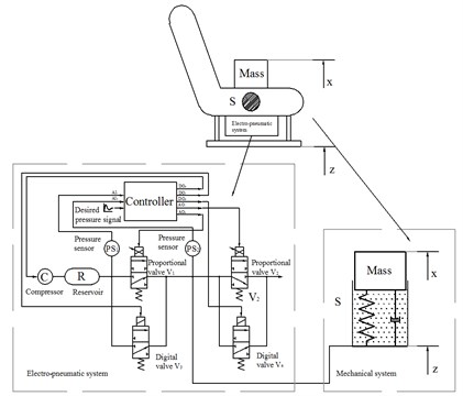
The seat with the implemented pneumatic spring contains an active vibroisolation element in accordance with the patented solution [1]. This system allows to change the stiffness of seat cushioning by a computer controlled electro-pneumatic feedback circuit. This electro-pneumatic part of the system comprises a compressor, reservoir of compressed air, 4 pneumatic valves, spring element, 2 pressure sensors and electronic control unit (Fig. 1). The pressure in the spring element is changed on user’s demand to chosen value or it is controlled by computer in accordance with chosen time course, for instance harmonic or triangular with predefined mean, amplitude and frequency.
Principally two different modes of operation are possible: constant stiffness and constant pressure. In the simpler constant stiffness mode, the pressure in the pneumatic spring denoted is set to chosen desired pressure at initial time. After that, the inlet and outlet valves are closed and volume of air inside the spring is then constant even if the system is mechanically loaded or not. In this mode the controlling system allows to set the fixed stiffness characteristics of cushioning. In the constant pressure mode, the electro-pneumatic feedback circuit tries to keep the pressure equal to for all time of the loading process.
There are two kinds of external loading taken into consideration. The first of them is sitting down of the passenger on the seat, and the second one is subsequent start of kinematical excitation of loaded seat by harmonic signal of displacement.
2. Model of the system
For purpose of creating the simulation model the system is divided in two parts in accordance with Fig. 1. The first one is represented by the controlled electro-pneumatic feedback circuit and the second one, the mechanical system, is represented by cushioning with implemented pneumatic spring.
Fig. 1The scheme of seat with implemented pneumatic spring
2.1. Model of electro-pneumatic feedback circuit
Electro-pneumatic system of pneumatic circuit consists of two kinds of pneumatic valves. The proportional valves denoted and in Fig. 1 are SMC – PVQ13-6M-08-M5-A. They are characterized by dependence of flow rate on pressure difference between pressure on input and output and by input coil current . This characteristics (Fig. 2) is taken from the datasheet [2] and by fitting algorithm it was transformed into two-parametric Eq. (1):
where 1, 2. In the pneumatic system there are also implemented two digital valves and of type SMC-S070B-6A. The function of these additional valves is to increase air flow in or out of pneumatic spring in case the control error between instantaneous pressure and desired value is too high. According with [3], flow characteristics of digital valve includes sonic conductance 0.083 l/(s.bar) and critical pressure ratio 0.28. According with [4], the formula for the flow rate calculation of digital valve is:
Choked flow:
Subsonic flow:
where 3, 4 and represents upstream pressure and downstream pressure respectively. The total air flow is then given by addition of flow rates of all individual valves as it is expressed by equation:
For the control of coil current, the PID algorithm is used in form Eq. (5):
where is the current controlling the proportional valve, is the control error given by expression:
Fig. 2Characteristics of proportional valve, from [5]
![Characteristics of proportional valve, from [5]](https://static-01.extrica.com/articles/17502/17502-img2.jpg)
Fig. 3Free body diagram of mechanical part
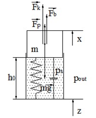
2.2. Model of mechanical part of the system
This part of the system is a simplified representation of seat cushioning with implemented pneumatic spring. According with [5], mechanical properties of flexible cushioning are described by restoring force given by nonlinear progressive function (7), and linear damping force given by Eqs. (10-12). Pneumatic spring is in a simplified way represented by closed air cylinder with internal pressure and the mass of passenger by value . Value of pressure inside the cylinder is given by differential Eq. (8) and finally with respect to free body diagram in Fig. 3 it is possible to set up the equation of motion of mass in form Eq. (9):
Used physical quantities in the system of Eq. (7-12) are: – excitation, – displacement of mass , – restoring force, – damping force, – force of pneumatic spring element, – the contact area between mass and cylinder (0.2 m2), – pressure inside cylinder, – pressure in the reservoir, – outside pressure (atmospheric pressure 0.1 MPa), 0.1 m – the height of cylinder at the initial position, – volume of cylinder, – temperature of gas inside cylinder, it is assumed to be constant (297 °K), 1.4 – adiabatic exponent, 287 J kg-1 K-1 – gas constant.
3. Numerical simulation
The system of equations derived above make up the mathematical model of combined electro-pneumatic mechanical system of the seat. The simulations are performed in Matlab software for two modes of seat operation, first in the mode of constant stiffness and second in the mode of constant pressure. For the purpose of this numerical experiment the excitation is given by harmonic function. Simulated process takes 20 seconds in total. At initial time the desired pressure in pneumatic spring element is set to 10 kPa, after that at time 6 s the seat is loaded by mass 50 kg which simulates sitting down of passenger, at time 10 s the external harmonic excitation is applied as a source of vibration load, finally, but only in case of constant pressure mode at time 16 s the desired value of pressure inside air cylinder is changed to 25 kPa under continuing vibration.
Values of constant used for calculation were 10 000 N/m, 0 N/m2, 1 000 N/m3 in case of restoring force Eq. (10), and 500 N.s/m in case of damping force Eq. (11). Outside pressure is equal to atmospheric pressure 100 kPa, pressure inside the air reservoir 200 kPa. Frequency of excitation is 1 Hz and amplitude is 10 mm. Parameters of PID controller were set to 7, 0 and 0, sampling time was 0.01 s in case of constant pressure mode. Then the system is in mode of active control. In case of constant stiffness all pneumatic valves are closed therefore total air flow is zero and the system is considered as passive one with no feedback control.
The results of simulations are depicted in Fig. 7 and Fig. 8 and comprises instantaneous pressure inside pneumatic spring, displacement and acceleration of mass , total air flow in/out the spring element , restoring and damping force of cushioning, force of pneumatic spring element and their summation.
The transmission of acceleration is calculated as ratio of amplitude of acceleration of mass and amplitude of acceleration of excitation () when excitation is harmonic function. When changing frequency of excitation , the transmission curve is obtained as in Fig. 9. It shows transmission curves in cases of desired pressure {1, 5, 10, 15, 20, 25} kPa in dependence on frequency of excitation in interval [1, 11] Hz.
Fig. 7Response of the system in constant pressure mode
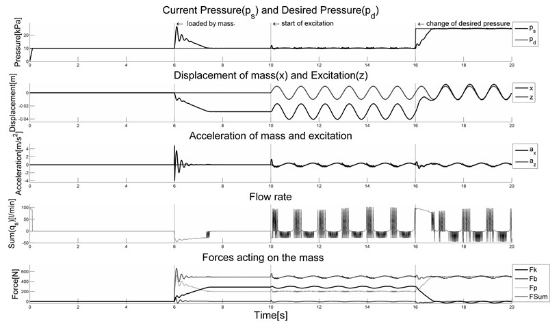
Fig. 8Response of the system in constant stiffness mode
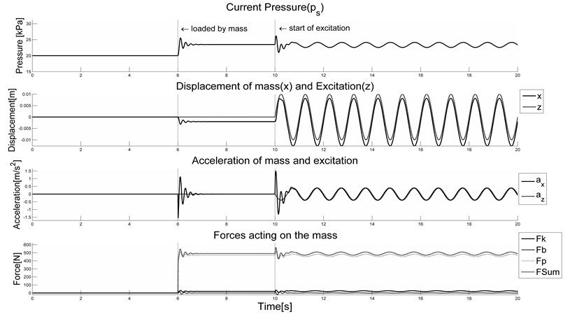
Fig. 9Transmission of acceleration
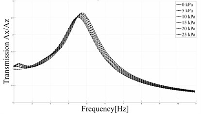
a) Constant pressure mode
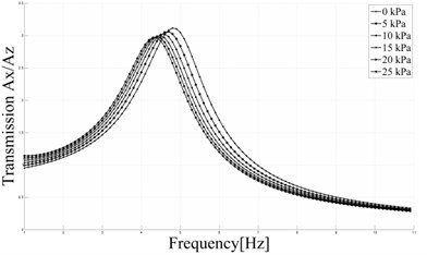
b) Constant stiffness mode
4. Conclusions
In this article the simulation model of seat with implemented pneumatic spring is introduced which allows to influence the hardness of the cushioning. The solution which comprises electro-pneumatic circuit with feedback control is described by mathematical model. This model allows to investigate the response of the system to kinematic excitation or the change of the desired pressure inside pneumatic spring. This pressure can be set to constant value or defined by deterministic course. The analysis of the response helps to find suitable model parameters which represent properties of real parts used for seat construction. These parameters are for example size and type of used pneumatic valves or pressure of air inside reservoir and others. The influence of constants of PID controller can be analyzed as well. The model will be used for evaluation of vibration isolation effect of the system which is possible to represent e.g. in form of the curves of transmission of acceleration.
References
-
Cirkl David Seat. Patent No. 303163, 2012.
-
Compact Proportional Solenoid Valve. Series PVQ, SMC Catalog.
-
3 Port Solenoid Valve. Series S070, SMC Catalog.
-
Kulakowski Bohdan T., Gardner John F., Shearer J. Lowen Dynamic Modeling and Control of Engineering Systems. Cambridge University Press, 2007, p. 219-243.
-
Cirkl David Mechanical Properties of Polyurethane Foam. Ph.D. Thesis, Technical University of Liberec, 2005, p. 134-136.
About this article

This article was written at the Technical University of Liberec, Faculty of Mechanical Engineering with the support of the Institutional Endowment for the Long Term Conceptual Development of Research Institutes, as provided by the Ministry of Education, Youth and Sports of the Czech Republic in the year 2016.
