Abstract
This article presents an analysis of vibrations in drivetrain of an 8×8 truck caused by an unbalanced rotating drive shaft. This truck is also used in military and fire sphere. The aim was to reduce the vibrations affecting the drivers, therefore, a transient computational model for analysis of drivetrain shaft deflection was created in Matlab software. This model was compared to the simulation of the transient behaviour of a drivetrain shaft 3D model with the use of FEM. To verify the computational models, measurements of the rotating shaft deflection and directional oscillations on the truck driveline were carried out in the original version and then also with the designed modifications of the components. The conclusion presents the interpretation of the results.
1. Introduction
The vibrations which make an impact on the driver also affect the drive comfort and may also affect the health of the driver. Therefore, an analysis of the vibrations has become important over the years, and not only with the passenger cars but also with trucks. The vibrations in trucks may be more intensive and may generate noise which makes the drive unpleasant for the driver. The 8×8 drivetrain of a truck is a complex dynamic system where the vibrations may come into being in any of its parts. This article focuses on the vibrations caused by an unbalanced rotating shaft in a driveline. This truck showed problems with vibrations and noise after reaching a certain speed, documented abroad where the limits of the European legislations are not valid. Therefore, it was assumed that it was caused by the revolutions of the drivetrain shaft. To analyse the deflection of the longest shaft the transient computational models were created using analytical and differential equations and Finite Element Method (FEM). The validation of the computational models was carried out by several measurements on the 8×8 and 8×4 truck driveshaft while driving on the highway. Vibrations and deflection of the longest shaft were measured. The conclusion presents interpretation of the results obtained from both the computational models and measured data. The further utilization of the computational models is also included.
2. Computational models
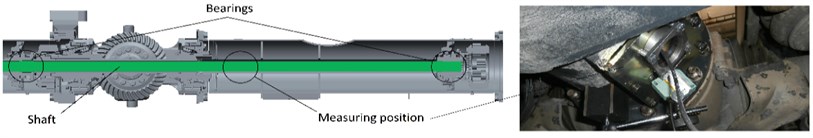
As mentioned in the introduction, for analysis two computational models of the shaft deflection while rotating were prepared. They are described further in the text. The computational model analysed by FEM is described only marginally, since it is used only as a certain monitoring indicator for the computational model created with the use of analytical and differential equations. Fig. 1 shows the 3D model of the drive shaft used for the FEM analysis.
Fig. 13D model of the drive shaft and the measuring position
2.1. Transient model of the shaft deflection – model I
To be able to verify the presupposed formation of vibrations on the truck caused by the unbalanced rotating shaft, a computational model of a rotating shaft with equations based on [1, 2] had to be created. The results of the calculations were subsequently compared to the measurement.
The computational model of the drive shaft includes the part of the shaft between the two bearings. The first bearing is located on the part of the axial differential of the front axle and the second bearing is located on the second front axle on the left (see Fig. 1). This part of the shaft is divided into mass points. By the measurement on the truck the initial deflection was set in the place of the deflection sensor. The shaft deflection is supposed to be based on these equations:
where is deflection in the middle of the analysed shaft length, – deflection in the measured point, – location of measurement, – shaft length, – initial shaft deflection in the individual points based on the given segments of the shaft, and – coordinates of the given shaft cross-section.
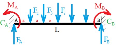
Fig. 2Drive shaft computational model and its boundary conditions
Centrifugal forces act on the individual mass points of the shaft. Their values were determined in each step of the simulation because deflection and shaft speed are increased. The following equation was used:
where is centrifugal force in the location of the individual mass points, – mass of the given mass point, – shaft deflection in the location of the given mass point, and – shaft angular speed. The boundary conditions are an import aspect for the shaft. It may be assumed that the boundary conditions will be between the hinged and fixed support because there are different shaft supports and clearance in the spline shaft. Therefore, three models were created where the most important one is presented in Fig. 2. It describes the shaft with prescribed rotational stiffness in the support. , are the moment reactions and , the force reactions. The boundary conditions for fixed support have to be based on the fact that if the beam is in fixed support on both sides it is a twice statically indeterminate task. Therefore, deformation conditions need to be added to gain force reactions and moment acting on the shaft. In fixed support the deformation conditions are defined after a partial release where the given end of the shaft is assigned zero displacement and rotation. Subsequently, 4 equations for 4 unknown are available – force equation, moment equation and equation for rotation and displacement calculated using the Maxwell-Mohr variant of the Castigliano’s theorem:
where is displacement in point , – rotation in point , – bending moment, – modulus of elasticity, and – quadratic moment of the cross section of the shaft.
For the beam with the defined stiffness in the support the force equation, moment equation and two equations for rotation in points and will be used. However, these rotation equations will not equal zero but they will be modified to the form of the following equations:
where , are rotations in points and , , – stiffness of the shaft support. For the hinged support it is a statically definite task, therefore, the reactions are determined based on the force and moment equations.
To gain values of the deflections in the individual steps, the equation of the deflection line is used where the rotation and displacement in the given place is determined by a gradual integration. The distance between the mass points is the same as the distance between the forces. The equations of the deflection line are defined as follows:
where is 1, 2, 3, 2, is 1, 3, 5, 2, is displacement and integration constants. These constants have to be determined from the boundary conditions, i.e. the zero displacements in the support. Furthermore, the equality of rotation values and deflections between the individual released segments has to exist.
Based on the equations above, the computational model is formed in Matlab software where the results of the measured drivetrain in the original design are compared with the modified solution and with the computational model of the original drive shaft. The results are presented in Fig. 5.
2.2. Transient model of the shaft deflection – model II (FEM)
Subsequently, analyses of the parts of the shaft and the whole drive shaft with the axle differential were performed using FEM. The transient solution was used similarly to the previous model. This computational model II works as a check for model I, therefore, there is no need for detailed description.
3. Measurement
The measurement of the rotating shaft deflections and directional vibrations was carried out with the use of IMC CRFX 400. It is a modular switchboard where the user may add the individual measurement cards as necessary. In this case, the card ICPU2-8 was used to connect the accelerometers and the card CRFX/ISO2-8 was used to record the analogue signals. Two three-axial accelerometers, a deflection sensor and a photoelectric reflex switch for speed measurement were connected to the switchboard. During the measurement the speed was increased gradually from the minimal value to the maximal and the speed gears were changed to gain data from the whole span of the truck speed. The measurement was carried out on a drivetrain of an 8×8 and 8×4 truck on a highway.
Subsequently, FFT spectrums [3] of measured vibrations and shaft deflections were interpreted depending on the shaft speed. Scripts to process the data in Matlab software were created. The signal of the shaft rotations is averaged and script searches for the shaft rotation with a step of 10 min-1. Thus, an index of data location in matrix is reached. This index looks for the data for interpretation of the vibrations and deflections. The measuring position is illustrated in Fig. 1.
Fig. 3Analysis of directional vibration in the Z-axis, drive 8×4, original and new drive shaft version
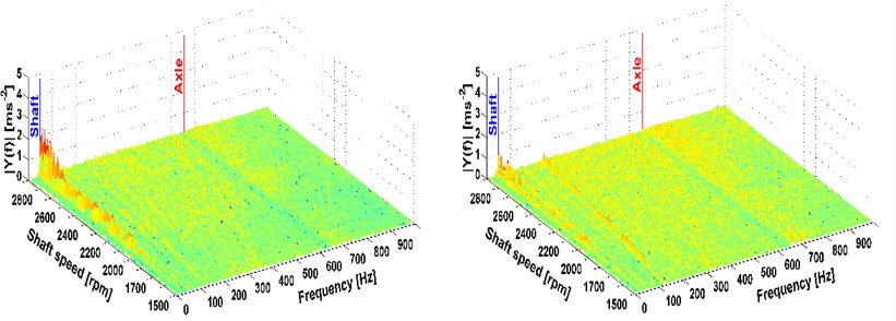
Fig. 4Analysis of directional vibration in the Z-axis, drive 8×8, original and new drive shaft version
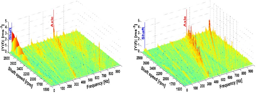
The shaft speed was measured by a sensor located on the main part of the switchboard. The speed signal was recorded as a mark per rotation from the photoelectric reflex switch. The measurement of the shaft deflections was carried out by a BAW M30ME-UAC10B-S04G sensor. By its parameters this sensor fulfilled the assumptions for measurement in the span of deflection up to 10 mm. The results of the gained data are shown in Fig. 5 where the states before and after drivetrain modification are compared. To measure the drivetrain vibration, two three-axial piezoelectric accelerometers Brüel & Kjær 4524 were used. To interpret the vibration, the FFT analysis from the segment representing the given speed was used. The sample frequency was 20 kHz and the number of samples was 8192. From these analyses FTT spectrums were calculated (see Fig. 3 and 4). These spectrums are illustrated only for the -axis because the results for the other axes are similar. The figures show the peak which stands for the 1st shaft speed harmonic order.
This is the most significant factor when it comes to the vibration affecting the driver. More peaks also occur mainly with the all-wheel drive which reflects the tooth frequency of the axle. But these frequencies are higher than 100 Hz [4], therefore, interms of comfort they cannot be reduced by the modification of the driveshaft. The comparison of measurements before and after the modification of the drivetrain is also shown. A considerable reduction of vibrations caused by the rotating shaft deflection was reached, which is illustrated in Fig. 3 and 4 on the right.
4. Results
Based on the deflection simulation and measurement it may be concluded that the computational models were chosen appropriately to assess the deflection, therefore, there is no need to extend the computational model I for the whole drive shaft.
The results are compared in Fig. 5.
Fig. 5Comparison of the measured values and computational models
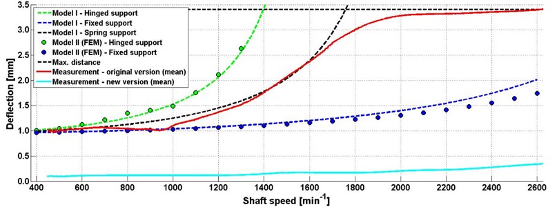
The measured data were for 6 speed gears; thus the most extensive span of the shaft rotations would be included especially in the area of 400-2600 min-1. These values were then averaged. Based on the dimensions of the constructive assembly around the shaft, the shaft deflection limit is 3.4 mm. The measured data show that the shaft deflects to such state that it leans against another part of the drivetrain.
The results of the deflection measurement, vibration analysis and model simulation show that the deflection of this shaft is the main cause of the driveshaft oscillation which is transmitted to the whole structure of the truck. To decrease the truck vibration, it is necessary to minimalize the shaft deflection and thus its unbalance. Therefore, a modification of the driveshaft was designed and carried out before the second round of measurement. The modification was a constructive solution to the shaft support. The shaft was split into two shorter shafts which were inserted into the socket rotating in the bearing.
The following measurement proved that the shaft deflection was considerably decreased (see Fig. 5). At the same time substantial decrease of vibrations on the truck was measured.
5. Conclusions
To analyze the shaft deflection, computational models were formed and their results were then compared with measurements. Based on the results, it may be concluded that the structure of the computational model is suitable for the analysis of the shaft deflection and may be used for further development of the driveshaft in all vehicles. The translational vibrations caused by the rotating shaft deflection were reduced by the constructional design. Based on the measurement carried out after the modification of the drivetrain as seen from Fig. 3 and 4, the support of the analyzed shaft led to the decrease of vibrations and a near loss of the 1st shaft speed harmonic order. This corresponds to the analysis of the shaft deflection and it may be univocally concluded that the shaft deflection and its unbalance was the main cause of the vibrations on the truck. The computational model I may be easily used for the development of the drivetrain with long shafts where the shaft deflection may occur deformation or unbalance
References
-
Budynas R. G. Shigley’s Mechanical Engineering Design. Eighth Edition, McGraw-Hill, New York, 2006.
-
Waller H., Schmidt R. Vibration Theory for Engineers: Theory, Simulation, Applications. First Edition, Wissenschaftsverlag, Zürich, 1989.
-
Tůma J. Vehicle Gearbox Noise and Vibration. Wiley, Chichester, 2014.
-
ISO 2631-1. Mechanical Vibration and Shock: Evaluation of Human Exposure to Whole-Body Vibration – Part 1. International Organization for Standardization, 1997.
About this article

This work is an output of the cooperation between internal BUT Research Project Reg. No. FSI-S-14-2334 and NETME CENTRE PLUS (LO1202) by financial means from the Ministry of Education, Youth and Sports under the “National Sustainability Programme I”.
