Abstract
The elastic support driver’s seat issue is very serious and the effort grows by manufactures to optimize their dynamic properties. The main optimization criterion is vibration insulation efficiency with regard to health research and their associated health standards and regulations. This article deals with the definition of the optimal driver’s seats properties on the examples of two systems with different kind of damping. In the first case use the springing support of driver seat uses a pneumatic spring and a telescopic hydraulic damper. In the second case is the damping effect is achieved by two pneumatic springs whose forces effect are phase shifted by a throttle valve which is in the connecting piping system.
1. Introduction
The springing support of driver seat (Fig. 1(a)) consists of a guide mechanism in which is placed a pneumatic spring. Parallel to the air spring is in a guide mechanism connected to a damper (Fig. 1(b)). Force effects and are phased shifted by .
Fig. 1a) Vehicle driver´s seat, b) Springing seat support with a hydraulic damper, c) Springing seat support with two air springs
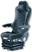
a)
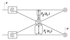
b)
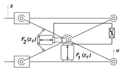
c)
In the original author’s solution there are two air springs which by themselves force’s effects acts against each together. They are pneumatically connected through the throttle valve, which achieves phase shifting their force effects and and thereby damping oscillatory motion (Fig. 1(c)).
When the vehicle is moving, the seat is kinetically energized by the movement of the floor. The excitation function is in fact in respect frequency and amplitude very diverse and its character depends on the road surface, vehicle suspension and on the speed. Driver’s seats producers asses the dynamic properties of the springing support and the vibration insulation effect based on their own practices and policies. It is usual measurement and evaluation of the feedback to the excitation signal which is measured when the vehicle is driving on the test polygon. General evaluation enabling an objective comparison of driver’s seats from different manufacturers in terms of vibration insulation efficiency is practically non-existent.
2. Mechanical model
The basis for evaluating the driver's seat suspension system is undoubtedly the creation and compilation of mechanical model and solving equations of motion.
For commonly known system of Fig. 2 the equation of motion can be written for simplifying assumptions of linearization dynamic parameters in the form:
where is the reduced mass of moving parts of the seat including the driver, is the coefficient of vibration damper damping, is the spring stiffness and a and are the springs and dampers transfers, is the displacement of the base under the kinematic excitation, is the absolute displacement of the object.
Eq. (1) is possible to write:
where is the relative displacement of the object and the base.
For pneumatically – mechanically system according Fig. 3 is possible to write equation of motion in the form:
where is construction damping coefficient, and are transfers of springs in mechanism.
The springs of the resilient differential pneumatic support have their geometrical characteristics given by polynomial functions of effective surfaces and and volumes and . The forces in the springs are also:
There are and deformations of the springs, and air pressures in the springs and and effective surfaces of the springs. The equation of motion of the support with the mass of the supported object is simple:
where is the relative displacement of the object and the base, is the displacement of the base under the kinematic excitation, is the absolute displacement of the object, is the construction damping of the mechanism, is the static load of the mechanism. The function is the equivalent force from the springs:
where and are transmission ratios of the springs.
Air pressures inside the springs obey the state equation of ideal gas:
where and are masses of the air enclosed inside the springs, is specific gas constant and , are temperatures of the air inside the springs.
The air exchange between the springs is described by isentropic air flow through the throttle valve. In the next two equations, the rate of air exchange depends on pressures and ; the pressure signs the higher pressure of , at a given time, is the other one. Which of the two pressures is higher determines the sign of the flow rate. The rate of air mass is then:
for subcritical flow conditions, where or:
otherwise. Critical pressure ratio is:
where is specific heat ratio for the air. In the Eqs. (9) and (10) are discharge coefficient and cross-section of the throttle valve.
Differential Eq. (8) supplemented by differential equation for air mass inside the springs describe the presented pneumatic-mechanical system. We have considered closed pneumatic system, so the air masses are bound by condition:
Having the thermal effects in the scope of this article, the temperatures , are considered as state variables. The evolution of the air temperatures in time is described by following differential equations derived from internal energy conservation (first law of thermodynamics):
where is isochoric thermal capacity of the air, is the ambient temperature and is the coefficient of heat transfer.
3. Comparison of hydraulic and pneumatic damping
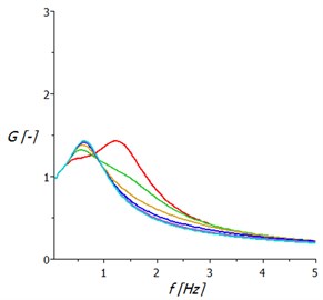
Based on solutions of equations of motion in the preceding paragraph a transmission frequency characteristic can be obtained which are usually concerned to displacement amplitude of the oscillatory movement of the seat. According to these data can evaluate the function of the spring base due to changes in the position of the driver to the vehicle controls and set the appropriate size of the damping coefficient.
In case the springing support with hydraulic damper according to Fig. 1(b) the transmission frequency characteristics are based on as shown on Fig. 2(a).
Particular damping characteristics correspond to the relative damping coefficient of 0.01 and 0.1 to 0.5 with step 0.1. Generally, it is possible to say, the damping has a positive effect when the system is erected near to its natural frequency. Outside of this region is the damping importance with respect to the displacement amplitude small to rather negative.
In case the springing support according to Fig. 1(c) are the transmissions frequency characteristics based on as is shown on Fig. 2(b).
Fig. 2Transmission frequency characteristics of springing support: a) with hydraulic damper, b) with two air springs
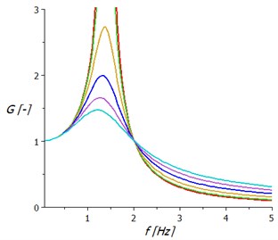
a)
b)
Individual characteristics correspond to different intensities throttling the flow of compressed air between the two air springs of the support. The diameters of the holes are graded from 1 mm to 3.5 mm with step 0.5 mm. The damping character of the oscillation is in this case favourable in the wider frequency range and the gain does not exceed the value 1.5.
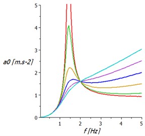
Another criterion of driver seat vibration insulation evaluation properties is acceleration value and frequency, which act on the driver and adversely affect the driving comfort.
In Fig. 3(a) are acceleration transmission frequency characteristics of springing support with linear hydraulic damper. It shows that damping is decreasing displacement amplitude, but significantly increases the acceleration values. This fact requires vibration insulation systems seats which show outside the resonance region negligible damping.
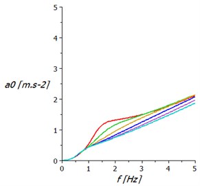
Fig. 3Acceleration amplitude frequency characteristics of springing support: a) with hydraulic damper, b) with two air springs
a)
b)
In Fig. 3(b) are the acceleration amplitude frequency characteristics of springing support with two air springs.
This springing system significantly reduces amplitude acceleration values compared to the classic springing support design. Acceleration amplitudes increase almost linearly with excitation frequency.
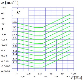
Vibration isolation properties of the driver seat can be quantified on the basis of hygiene standards. There is medical research, where the result is the definition of sitting person’s comfort under the influence of acceleration of a certain amplitude and frequency. In Fig. 4 are graphs taken from the internationally valid standards ISO 2631, ISO 5982 and VDI 2057.
Using these findings could contribute to an objective evaluation of vibration insulation properties of driver seats and to remove the element of subjective assessment, which currently dominates among the manufacturers of driver seats.
Fig. 4The amplitude and frequency dependence of the sitting human comfort on acceleration
Using the coefficient the vibration insulation level of the driver seat properties can be deduced. In Fig. 5(a) dependence the coefficient is calculated on seat’s excitation frequency with hydraulic telescopic shock absorber and Fig. 5(b) shows this dependence on the seat with two pneumatic springs.
Fig. 5Frequency dependence the coefficient of seated human loading on the acceleration of seat: a) with hydraulic telescopic shock absorber, b) with two air springs
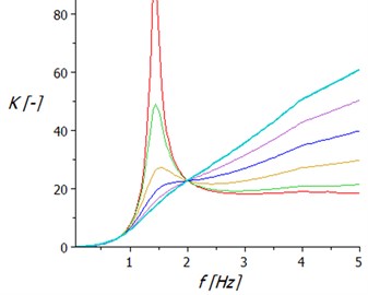
a)
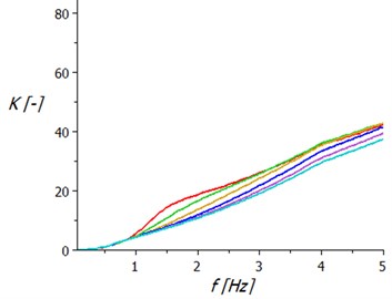
b)
4. Conclusion
There are many technical problems that are connected with a necessity of the minimization of the vibrations, especially in the automotive industry. There are many types of equipment which have an excitation through the movement of the foundation. The typical instance of this set is a driver seat. With vibration isolation of these objects, there are further problems that come from variable excitation frequency. It is clear that the condition of the sufficient difference between the force excitation frequency and resonant frequency of the dynamic systems cannot be ensured at all times. In these cases, it is necessary to use special supports with the possibility of the stiffness changing, and to tune the natural frequency of the system appropriately. In the paper are presented two possibilities of the driver’s seat design. One of them is the classical solution with a hydraulic damper. The second one is an original solution of authors which has two pneumatic springs in the guide mechanism.
This original solution presents a pneumatic spring system with a differential configuration and the throttling of the air flow between the springs. The springs act one against the other. This system can be used with benefits to the vibration isolation of the objects of the systems with kinematic excitation, e.g. driver seats, ambulance couchettes, etc. Based on the frequency spectrum of excitation, it is possible to choose the optimum cross-section of the throttling element and achieve efficient damping of vibration in a relatively broad range of low excitation frequencies. Similar results can be seen by measurement of the real system. Evaluation of both seats is made on the basis of simulation of vibration excitation at constant amplitude support displacements at frequencies from 0 to 5 Hz. The obtained frequency characteristics of kinematic quantities are further processed for the purpose the sitting human loading of vertical acceleration coefficient determination. Calculation results showed that a qualitatively higher level of vibration insulation properties seat has the seat with two air springs.
References
-
Harris C. M. Shock and Vibration Handbook. Fifth Edition. McGraw-Hill, New York, 2005.
-
Pešík L., Skarolek A. Tuning of vibration isolation differential pneumatic system by means of throttle valve. Transactions of the Universities of Košice, Research Reports from the Universities of Košice, 2nd Edition. Technická univerzita v Košiciach, Košice, 2011, p. 191-196.
-
Pešík L., Skarolek A., Vančura M. Supporting of Driver’s seat with the Controled Load Characteristik. Proceedings of the 52th Conference of Departments of Mechine Design, Technical University of Ostrava, Vol. 1, 2011, p. 175-178.
-
Homišin J., Kaššay P. Comparison of Tuning in Shipping System Using Pneumatic Tuners of Torsional Oscillations. Machine Modeling and Simulation, Scientific and Technical Society at the University of Žilina, Žilina, 2009, p. 147-154.
About this article

This publication was written at the Technical University of Liberec as part of the Project “Innovation of Products and Equipment in Engineering Practice” with the support of the Specific University Research Grant, as provided by the Ministry of Education, Youth and Sports of the Czech Republic in the year 2016.
