Abstract
Our study deals with the vibration isolation at the suspension seat to reduce the human body’s harmfulness from the oscillation. The unwanted vibration transmitted from unpredicted road roughness via chassis throughout to the driver in widely range of excited frequency. The passive suspension cannot overcome the problem, but the active suspension is too complicate and expensive for this system. Consequently, we propose the idea concerning an adjustment of the air spring stiffness in order to change the characteristic of the system. The air spring stiffness was initially identified via the vibration investigation and measurement. After that, the method of stiffness adjustment is proposed. The result show that the weight root mean square vertical acceleration must follow the comfort range following ISO 2631-1.
1. Introduction
Working in the mine as heavy truck’s driver is often suffer from health problems induced especially from the driving environment like noise and vibration throughout excited frequency range. The vertical acceleration transmitted from the road roughness over the vehicle suspension and body through the seat and the human’s body, causing to long-term health problem and physical harmfulness. Following this topic, the whole body vibration (WBV) was introduced in many studies such as in [1]. The content aimed at evaluation WBV in terms of the vertical suspension, seat transmissibility and seat effective amplitude transmissibility. The test conducted by the healthy male in the field measurements by detecting floor to seat transmissibility, floor to thigh transmissibility, seat to thigh transmissibility and root mean square magnitude. ISO 2631-1 is the standard for comfort level, evaluated via the weighted acceleration. Refer to [2] It correlated the weighted acceleration, vibration dose value and exposure time. The passenger car seat vibration analysis, mentioned in [3], applied the same standard as previous. This project helped us to understand the dynamics comfort, ride comfort index and the transmissibility at difference terrain roads.
Seat suspension systems were proposed in order to isolate the vibration and affect ride comfort. Generally, it consists of the passive mechanism with spring and damper that can be useful for limited frequency range. For this reason, the semi-active and active suspension system were applied as well as the control algorithms. They were developed in many studies, e.g. in [4], the hybrid Skyhook and Groundhook together with feedforward compensation were applied to the seat and driver model of the military vehicle. Active force control technique integrated with artificial neural network stated in [5] was applicable and this method was computationally simple and efficient subjected to various types of road profile inputs and disturbances. It was interesting to study the dynamic characteristic of suspension seat refer to [6]. The vibration transmission was examined with different seat configurations and loading conditions.
Air spring is the element, which widely uses instead of the conventional one because it can change of the stiffness and provides the adaptive characteristic of the system stiffness and consequently the system natural frequency and damping ratio. There are some drawbacks of the air spring for example; the pressure control via pneumatic control valve, the complication of the system and etc. Researchers tried to develop the model of air spring. In [7] presented the dynamics model with the frequency dependence of the stiffness characteristic. Fuzzy control algorithm was proposed in [8] to regulate and isolate the air spring system of the quarter car suspension.
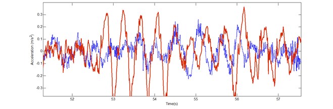
Our study aimed at suppression of vertical acceleration to gain better riding comfort and less health problem since truck driver’s health problem like the back pain, hearing disability suffers from vibration force during the working hours approximately 9 hours per day. We identified the problem initially by field measurement from the truck in mining area as shown in Fig. 1. Then we measured inertial response at the floor (chassis) and at the seat structure, when the truck was driven along the local road conditions. It was found that seat had a large amount of vibration in vertical direction compare to the vibration of the truck’s chassis in Fig. 2. Due to our off-road environment, it brought us the wide range of frequency. For this reason, the passive isolation was not sufficient throughout the working range but the active one has also the disadvantages because of its complication and expensiveness. The modification of the passive one should be taken into account. The air spring is the stiffness element, which can be adjusted by the input pressure. It make the system’s natural frequency change as well as damping ratio. The fuzzy algorithm is help to tuned up via frequency response assuming small displacement. Finally, the control algorithm was applied and the oscillation signal diminished in the acceptable magnitude referring to ISO 2631.
Fig. 1The truck and the environment in this experiment with the sensors
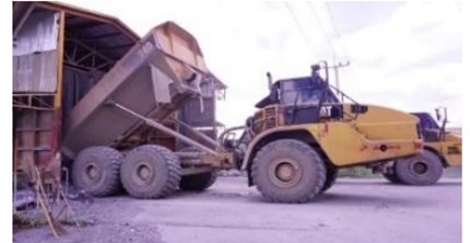

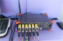
Fig. 2The vertical accelerations of the passive seat suspension measured at floor (…..) and seat (___)
2. System stiffness
Since the nonlinearity of the air spring over the driving frequency range which depend on air pressure and the frequency, the parameters must be estimated by both quasi-static test and system identification technique
2.1. Input signal
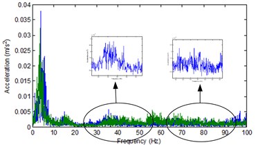
The input of our system originated from the road profile via the chassis suspension system. It should be amplified or attenuated due to the characteristic of the system at corresponding frequencies. To modify such as system is the massive work and it was not in our scope. Considering the acceleration signal as the system input in time domain in Fig. 3, from the truck chassis or floor, the signal can be treated as harmonic one with various frequency, as we analyzed the signal by means of FFT. The magnitudes and frequencies were clearly explained in Fig. 4. The low frequency range came generally from sprung mass, the middle and high range came from others source of vibration.
Fig. 3The random vertical accelerations of chassis input
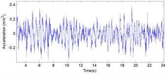
Fig. 4Frequency spectrum of the vertical accelerations of chassis input in case of (blue) no load and (green) load
2.2. Seat structure
The structure is modeled in one degree of freedom based excitation vibration system. It consist of the air spring and damper. The stiffness can be adjusted via the pneumatics proportional control valve as demonstrated in Fig. 5. The spring stiffness at the certain pressure can test by tension and compression test. Unfortunately, the stiffness is not only depend on the air pressure but also the exciting frequency, the estimation technique must be used.
Fig. 5a) Seat structure, b) air spring control valve
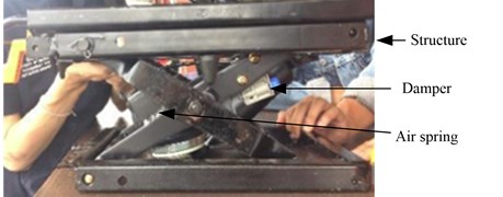
a)
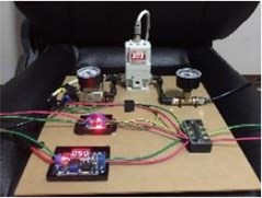
b)
2.3. Stiffness determination
Air spring stiffness is determined by the method shown in Fig. 6. We use the measurement input as input of our system model in each frequency by Fast Fourier transform. The model transfer function is primary approximated as 1 DOF vibration isolation system as mentioned in Eq. (1):
where is frequency ratio and is damping ratio.
After that, the harmonic signal is generated and tuned. The objective is to minimize the quadratic root mean square error between model and simulation one, which identified as in Eq. (2):
When they were not in the threshold, the new iterations would be again.
The moving average acceleration can be calculated following Eq. (3) in the period of determination time:
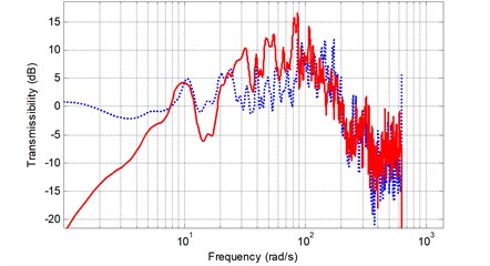
The frequency response transmissibility from the measurement is plotted in Fig. 7 by varying of the stiffness. The approximate response curves are compared to the measurement one and they are in agreement, although they are not perfectly fit especially in the high frequency range due to some uncertainties. We also assume small structure displacement in order to get rid of the effect of spring and damper nonlinearity terms.
Fig. 6Stiffness determination
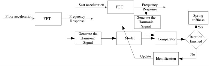
Fig. 7Open loop transfer function (left) by varying the stiffness
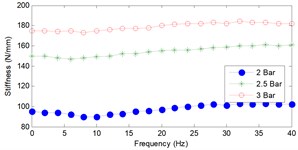
After that process, we gain the stiffness by the slope of the graph between force and displacement from quasi static test in tension and compression in Fig. 8. In our displacement range, we define the small stroke in our structure; the stiffness depends on input pressure. At the same time, we tried to simulate the model in each frequency as state in Fig. 6 and we have got the relationship, which explained the magnitude when the frequency change as well as pressure which result in Fig. 9.
Fig. 8The relationship between force and displacement in millimeters
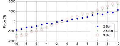
Fig. 9The relationship between stiffness and input frequency
3. Control system
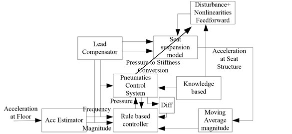
The control algorithm is proposed as illustrated in Fig. 10. The system input is the acceleration at the floor in time domain. by the moving point method, the frequency is estimate based on the history of the oscillation in an amount of time. This acceleration must excite the system so that the seat oscillation is detected and evaluated if the moving average value is not exceeding the threshold of ride comfort. The pressure and its derivative are taken into account as input. We limit the rate of change of the pressure because of limitation of the hardware as mass flow rate. The ruled based controller is applied in conjunction with the knowledge based data like the interpolation of Figs. 8 and 9 as look up table and etc. Finally, new stiffness value is update in the rate of 5 Hz.
The system model consists of 3 parts, the seat suspension system defined in Eq. (1), the pneumatics system and the sensor system. We approximated the response characteristic of the valve as first order system and the accelerometer as second order one which has the response time more than 10 times faster than the system response. the lead compensator is initially applied and designed based on the open loop frequency response of integrated 3 parts of the system which must compensate the system stability over the range of the stiffness.
Fig. 10Control algorithm
4. Result and discussion
Applying the controller discussed in Section 3, we tested it in real environment and we investigated the magnitude of the output responses in Fig. 11, which attenuated and the weight root mean square acceleration over measurement range mentioned in Eq. (4) is 0.2495 m/s2. It is not exceed the ride comfort criteria concerning ISO 2631 as 0.315 m/s2:
where is frequency weighted acceleration at time , is exposure duration
In Fig. 12 show the adjustment of the air spring stiffness in each update time corresponding data from Fig. 11. Between 144-146 seconds, the frequency is quite low, and then the stiffness should be bigger and the system natural frequency is higher. It leads to the small amplification of the system at that frequency. on the other hand, the vibration between 149-153 seconds has smaller frequency; we let the smaller stiffness that leads to isolation zone of the excited one.
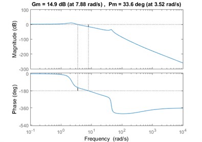
The stability of the system will be identified by the closed loop frequency response over the stiffness range. the fifth order transfer function is considered and the lead compensator. We tried to investigate the closed loop system gain margin. It is found that there is the positive phase margin varying form 40 degree for minimum stiffness available and 33.6 degree at the maximum one.
Fig. 11Acceleration at floor and seat after perform controlling
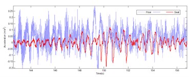
Fig. 12The variation of stiffness
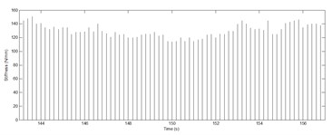
Fig. 13Bode plot of the closed loop frequency response for maximum stiffness
5. Conclusions
Our study deals with air spring stiffness adjustment in order to reduce the vibration at the driver seat. We identified the problem via the field measurements which give us the advantages about parameter estimation. The control algorithms are applied and the results show that both oscillation amplitudes are notably decreased. The weight root mean square acceleration is preferable recommended by ISO 2631
References
-
Adam S. A., Abdul Jalil N. A. Vertical suspension seat transmissibility and SEAT values for seated person exposed to whole-body vibration in agricultural tractor preliminary study. Proceeding of the Engineering Physics, Procedia Engineering, Vol. 170, 2017, p. 435-442.
-
Duarte M. L. M., De Araujo P. A., Hotra F. C., Vecchio S., De Carvalho L. A. P. Correlation between weighted acceleration, vibration dose value and exposure time on whole body vibration comfort level evaluation. Safety Science, Vol. 103, 2018, p. 218-224.
-
Joseph F. A., Issac J. C., Pualson T. J. Low frequency vibration analysis on passenger car seat. International Journal of Scientific and Engineering Research, Vol. 4, Issue 8, 2013.
-
Kieneke R., Graf C., Maas J. Active seat suspension with two degrees of freedom for military vehicles. 6th IFAC Symposium on Mechatronic Systems, Hangzhou, China, 2013.
-
Gohari M., Tahmasebi M. Active off-road seat suspension system using intelligent active force control. Journal of Low Frequency Noise, Vibration and Active Control, Vol. 34, Issue 4, 2015, p. 475-490.
-
Qiu Y. Dynamic characteristics of a suspension seat determined in laboratory study. Journal of Ergonomics, Vol. 7, Issue 6, 2017, p. 220.
-
Gavriloski V., Jovanova J., Tasevski G., Djidrov M. Development of a new air spring dynamic model. FME Transactions, Vol. 42, 2014, p. 305-310.
-
Zepeng G., Jinrui N., Lian L., Xiaolin X. Research on air suspension control system based on fuzzy control. Energy Procedia, Vol. 105, 2017, p. 2653-2659.
About this article

