Abstract
Structural glass represents a relatively innovative and not well-known solution for constructions, where it is largely used for facades, roofs, footbridges, etc. There, multiple (sandwich) glass members can interact with traditional building materials, and should offer appropriate fail-safe performances, within the full life time. However, severe operational conditions, or extreme loads, can increase the intrinsic vulnerability glazing systems. In this paper, the dynamic characterization and damage diagnostic assessment of an existing glass footbridge is carried out, based on Operational Modal Analysis (OMA) techniques.
Highlights
- OMA techniques are applied to an in-service glass footbridge
- The actual performance of the pedestrian structures is assessed
- Analytical methods cannot capture the complex mechanical performance of the suspension system
- Finite element numerical models are used in support of the diagnostic analysis
- Severe ambient conditions can markedly affect the vibrational performance of in-service pedestrian glass structures
1. Introduction
In the last decades, glass has been increasingly used as load-bearing material. Although it represents a relatively new solution for constructions, requiring appropriate design methods, knowledge and experience, glass is actually largely used for facades, roofs, footbridges. Given a series of intrinsic features (i.e. material properties, types of restraints, operational conditions, etc.), however, special care should be spent not only at the design stage - to ensure appropriate fail-safe requirements – but also in the whole service life of glass building components and structures (see for example [1, 2]).
The vulnerability assessment of glazing systems under dynamic and/or extreme loads (i.e., seismic events, human/traffic-induced vibrations, shocks, etc.), including severe climatic conditions, is still an open topic, requiring huge efforts. Additional consideration must be spent for existing glass systems, that in several cases can be designed as “temporary” structures (with a nominal life-time of 10 years), but can be in any case subjected to severe degradation phenomena and/or unfavorable operational conditions that could compromise their nominal design performance, hence resulting in unfavorable configurations, excessive vibrations, large deflections, stress peaks (Fig. 1).
In this regard, Operational Modal Aanalysis (OMA) techniques can represent a robust tool for diagnostic investigations, being conventionally recommended when the vibration parameters of a structure cannot be rationally estimated by means of analytical models (due to specific restraint configurations, or uncertainties on the material properties, including possible viscous effects in polymers and adhesives, as it is in the case of glass systems) or complex damping phenomena. According to classical dynamics, the governing equation for a vibrating body can be described via a simple spring () – mass () system with damping , that is [3]:
where is the displacement from the static-equilibrium position, with the input loading (i.e., direct or indirect).
The free-vibration response of the system ( 0) is strictly related to its geometrical and mechanical features, where the damped circular frequency is:
As far as the damping term is small (as in the case of glazed systems [4]), it is:
with the critical damping, and hence:
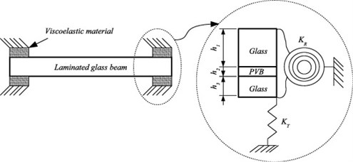
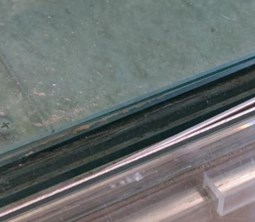
Following Eqs. (1)-(4), OMA techniques are suitable for the reliable on-site estimation of the dynamic properties of a given glass structure, even in presence of non-ideal boundary conditions. The primary effect is that the sensitivity of design configurations to the actual mechanical properties of supports (i.e., where the use of soft layers is usually preferred, to avoid stress peaks, see Fig. 1(a)) can be investigated via non-destructive experiments. Further uncertainty can derive from the use of laminated glass (LG) systems, where the bonding interlayers mechanical properties are strongly susceptible to several influencing parameters (detail of Fig. 1(a)). In this regard, a damage diagnostic investigation can be carried out based on dynamic identification techniques.
Fig. 1a) Laminated glass (LG) member with viscoelastic supports, b) typical loading scenario due to human induced vibrations
a)
b)
2. Design requirements for horizontal structural glass systems
Structural glass floors and slabs should be checked under ordinary service loads towards maximum deformations (Service Limit State) and stresses (Ultimate Limit State) due to permanent and accidental loads, see [1, 2]. Given a slab span , the cumulative deformation must not exceed the limit value /250, but even more restrictive limits can be accounted for special boundaries. The maximum stress peaks must then be lower than the design resistance, being dependent on a wide set of geometrical/mechanical parameters (i.e., type of glass, boundary and loading condition, time, edge treatments, holes, etc.). The post-cracked residual resistance of the glass system must be finally verified, at the Collapse Limit State, to ensure appropriate redundancy, in case of accidental fracture of one/more glass components. This is why glass slabs should be composed of laminated (LG) composite sections with minimum three glass layers. In addition, given a LG plate, continuous linear restraints along the four edges should be preferred. For safe post-cracked performances, special care / restrictive requirements should be finally taken into account for the choice of glass types (and their combination) within a LG section [1, 2].
Besides such a series of primary safety requirements, an additional key aspect in operational conditions is represented – under ordinary loads – by maximum vibrations, requiring dedicated calculation methods (i.e., [4]). In most of the cases, the optimal vibrational condition can be considered satisfied as far as the fundamental frequency is minimum 8 Hz. This request may involve critical issues for some categories of glazed structures, being often characterized by small thickness-to-size ratios, high flexibility and slenderness, compared to other constructional materials. Further uncertainty on the service performance of glass floors and footbridges may derive from the partial / progressive degradation of restraints or material components (i.e. Fig. 1), thus resulting in variable mechanical restraints and loading configurations that should be monitored in the medium-long period.
3. Case study footbridge
3.1. Structural system
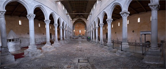
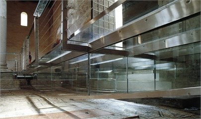
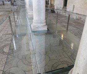
The glass suspension footbridge realized in the Basilica of Aquileia (Italy) is investigated in this paper (Fig. 2). The Basilica’ monument, listed by UNESCO as a World Heritage Site, includes the largest / one of the best preserved early-Christian floor mosaics (750 square meters), and attracts 300,000 visitors every year (Fig. 2(a)). The examined footbridge was realized in the early 2000, in the form of a transparent platform, to protect the floor mosaics and allow for their optimal visibility, by minimizing the visual impact on the Basilica. 118 LG panels were used, to mechanically interact with steel bracing tendons and framing members.
Fig. 2Case study footbridge: a) general view; with details of: b) main entrance, c) central nave path
a)
b)
c)
The main entrance platform consists in 20 LG panels (≈2.9×14.5 m the covered surface) that allows to reach the Crypt (left side) and the nave path (right side). The maximum size of each LG plate is ≈2.4×0.95 m, with linear supports along the four edges, based on supporting frame members. The framing system is longitudinally braced by means of 4 reinforced glass beams, with top/bottom steel flanges and glass segments to cover a parabolic shape (Fig. 2(b)). These reinforced beams span through the platform, to provide an appropriate performance of the overall suspension system. Along the nave path, see Fig. 2(c), the LG panels have mostly similar dimensions, up to a maximum of 1.65×2.65 m, but with linear supports along the two short edges only, hence resulting in a nominal span up to ≈2.55 m (Fig. 2(c)). To limit the deformations of these beam-like LG floor components, a bracing system composed of pre-stressed pairs of steel tendons was originally designed. The tendon pairs, intended to half the total span of the glazed floor, are solidarized at the ends with the steel supports, while a mid-span unilateral contact mechanism was designed to realize a composite steel-glass system with the upper LG plates.
3.2. State-of-the-art
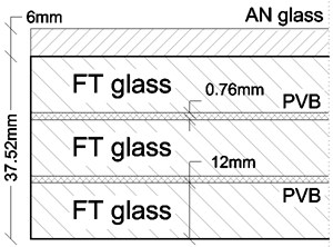
All the glass panels of the footbridge consist in a triple LG section (12 mm the thickness of each Fully Tempered ply), and a top, unbonded annealed glass panel (Fig. 3(a)). The LG layers were connected via 0.76 mm thick PVB foils.
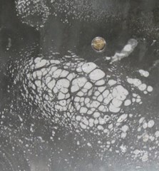
Actually, the structure suffers for a combination of high humidity, non-controlled temperature and limited maintenance efforts (i.e. Figs. 3(b), (c)) that suggest detailed investigations, in order to properly assess the real capacity of the structure, with respect to the operational conditions. On one side, for example, it is well known that PVB foils work as a “weak” shear bonding connection, being sensitive to time, temperature, severe humidity, fatigue, etc. [1, 2]. This is also the case of the pre-stressed tendons, where the originally imposed tension force mostly vanished. On the other hand, the footbridge context does not allow invasive and/or destructive experiments.
Fig. 3State-of-the-art: a) LG cross-section, b), c) examples of observed degradation phenomena
a)
b)
c)
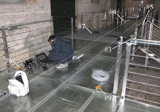
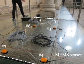
3.3. On-site vibration experiments: methods and instruments
The vibration tests were carried out in the late November 2017, in the early morning (8-10), in order to do not interfere with possible celebrations or tourist visits. An average temperature of 6.5°C, with 87 % the relative humidity, was recorded within the Basilica.
Fig. 4On-site experiments: test setup for: a) main entrance platform (S-E series), b) the central nave (S-CN series)
a)
b)
All the measurements were performed with the Micro Electro-Mechanical System (MEMS) accelerometers prototyped in [5]. Special consideration was spent for the LG panels at the main entrance and along the central nave (Fig. 4). Output-only data were collected via six sensors, based on random human induced vibrations. These included a single male subject (60 kg his weight) passing with a consistent walk on the footbridge, back and forth along the main entrance platform, and along the central nave path. The subject was also asked to cross the footbridge with a less pronounced walk. In both cases, the step frequency was in the range of 2-3 Hz, and the typical record was characterized by a duration of 4-5 minutes. In this paper, selected testing scenarios are discussed, with special attention for:
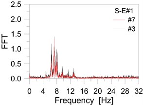
• S-E#1 scenario: main entrance platform, normal walk.
• S-E#2: main entrance platform, consistent walk.
4. Test results
All the collected records were post-processed in SMIT [6]. For the entrance platform, given the actual boundaries, global measurements were carried out along the ≈14.5 m span of the bracing girders. Otherwise, the tests in the nave path were focused on single, beam-like LG plates.
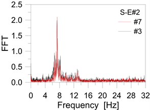
More in detail, the experiments on the entrance platform gave evidence of a fundamental frequency of ≈7.5 Hz (see Fig. 5). Maximum vibrations were observed in the central region of the platform, sensors #7 and #3. Given the complex mechanical interaction of all the involved members (i.e., LG plates, steel members, girders, see also Fig. 1), however, a more detailed analysis is required before considering possible retrofit and stiffening interventions.
Fig. 5On-site experiments: main entrance platform: a) normal, b) consistent walk
a)
b)
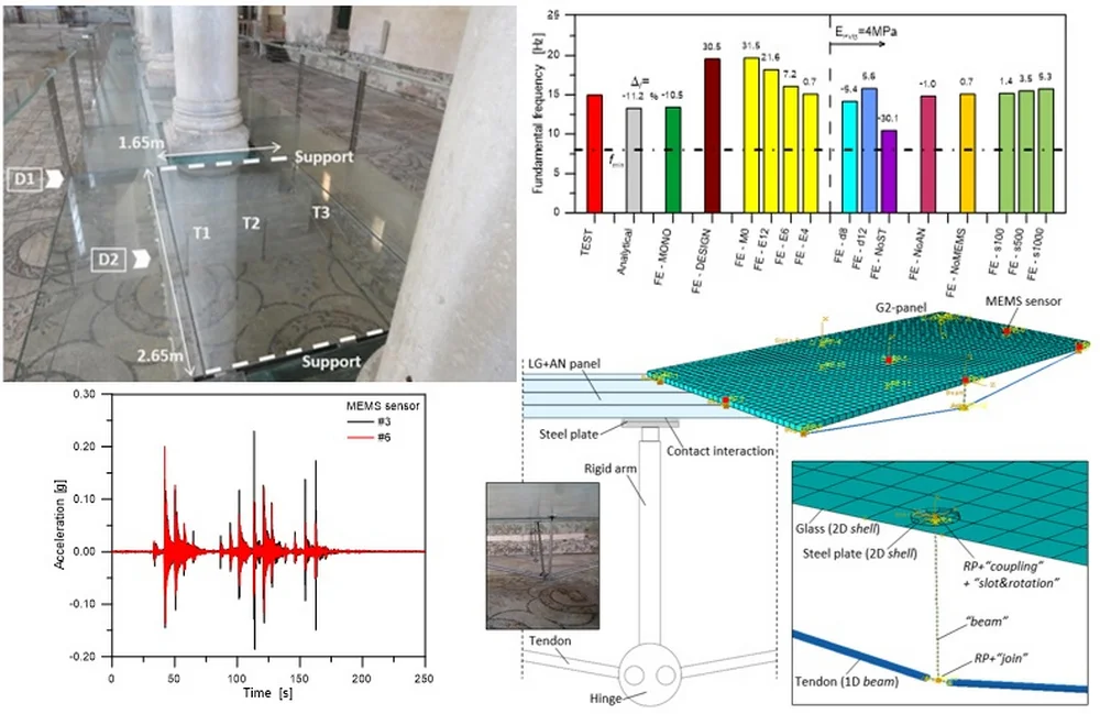
Fig. 6On-site experiments: central nave LG panel. Parametric study (ABAQUS)
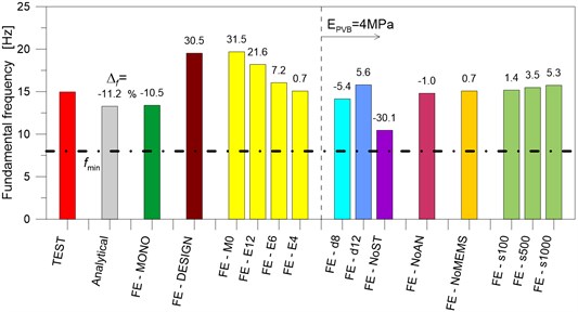
This is not the case of the LG plates along the nave path, where the fundamental frequency was calculated in 14.97 Hz. The reference modal shape was found to have the overall deformation of a beam, with the added contribution / uncertainty due to the “sandwich” cross-section (LG plate + top annealed layer) and to the steel tendon pairs. In this regard, an accurate Finite Element (FE) numerical model was implemented in ABAQUS [7, 8], to account for the actual nominal geometrical and mechanical properties of the examined system, including a reliable description of boundaries. The dynamic parameters of the structure were numerically investigated via a wide set of parametric analyses, giving evidence – via sensitivity studies – of the influence of several key parameters, like the presence of bracing tendon pairs, their unilateral contact support, the level of pre-stress in the tendons and specifically the shear stiffness of PVB foils.
Worth of interest is that the FE study gave evidence – based on the experimental feedback herein discussed – of the actual state of the system, namely a degradation of PVB stiffness and a mostly full loss of prestress in the steel tendon pairs. In Fig. 6, the fundamental frequency variation is shown for the parametric FE models, with respect to test predictions (‘TEST’) and to simple beam-like analytical calculations (‘Analytical’). Compared to the original “design” of the examined components (and a nominal shear stiffness of PVB foils in the order of 8MPa, for room temperatures / short term loads [1, 2]), the optimal correlation with tests was found with a relatively weak PVB bonding connection for the LG layers (i.e., 1.3MPa the estimated shear stiffness, corresponding to a modulus of elasticity of 4 MPa).
5. Conclusions
In this paper, a preliminary dynamic characterization of an existing suspension glass footbridge was presented, based on Operational Modal Analysis (OMA) vibration tests. The glazed walkway in the early-Christian Basilica of Aquileia (Italy) was taken into account. Based on test measurements and on-site observations, it was shown that a combination of multiple aspects can affect the structural performance and dynamic properties of the examined system, as well as of existing glass structures in general, hence requiring careful consideration towards fail-safe design and vulnerability assessment purposes, also during their whole life time. In this regard, the presented test results confirmed the importance of non-destructive diagnostic investigations, and the key role of OMA techniques for the definition of a reliable state-of-the-art scenario, for continuous monitoring purposes and for the optimal planning of dedicated maintenance interventions.
References
-
Feldmann M., Kasper R., et al. Guidance for European Structural Design of Glass Components – Support to the implementation, harmonization and further development of the Eurocodes. Report EUR 26439 – Joint Research Centre-Institute for the Protection and Security of the Citizen, 2014.
-
Istruzioni per la Progettazione. l’Esecuzione ed il Controllo di Costruzioni con Elementi Strutturali in Vetro (in Italian). National Research Council (CNR), Roma, Italy, 2013, www.cnr.it.
-
Clough R. W., Penzien J. Dynamics of Structures. McGraw-Hill, ISBN 0-07-011394-7, 1993
-
Bedon C., Fasan M., Amadio C. Vibration analysis and dynamic characterization of structural glass elements with different restraints based on operational modal analysis. Buildings, Vol. 9, Issue 1, 2019, p. 13.
-
Bedon C., Bergamo E., Izzi M, Noè S. Prototyping and validation of MEMS accelerometers for structural health monitoring – the case study of the Pietratagliata Cable-Stayed Bridge. Journal of Sensor and Actuator Networks, Vol. 7, Issue 3, 2018, p. 30.
-
Structural Modal Identification Toolsuite. Smit, http://smit.atlss.lehigh.edu.
-
Dassault Systémes. ABAQUS Computer Software v. 6.14. Providence, RI, USA, 2017.
-
Bedon C. Diagnostic analysis and dynamic identification of a glass suspension footbridge via on-site vibration experiments and FE nuemerical modelling. Composite Structures, Vol. 216, 2019, p. 366-378.
Cited by
About this article

The So.Co.Ba. Foundation – “Società per la conservazione della Basilica” is gratefully acknowledged for facilitating the vibration experiments. The research study herein summarized is part of the INVERSE project – Experimental and numerical dynamic identification of structural glass elements (Università degli Studi di Trieste – FRA2016-BEDON).
