Abstract
Adaptive control has been used for active vibration isolation and vehicle suspensions systems. A model reference adaptive control law is used for the plant to track the ideal reference model. In a model reaching adaptive control approach, the ideal of a skyhook target without using a reference model is achieved. In this paper, a novel approach, a model reaching adaptive-robust control law is studied for active vibration isolation systems. A dynamic manifold for ideal system is defined using the ideal of a skyhook target model system parameters. First, a new Lyapunov function is defined. Based on the Lyapunov stability theory, a model reaching adaptive and a robust control laws are derived for the uncertain system to reach the ideal manifold. Parameters and upper bounding functions are estimated as a trigonometric function depending on the relative displacements, velocities and the defined manifold. The developed adaptive and the robust compensators are combined and this combination is proposed as an adaptive-robust control law. After that, the controller is applied to a vehicle suspension system and the ideal of a skyhook target without using a reference model is achieved. The results also show that the proposed robust control law can increase the comfort of the vehicle active suspension systems and the ride comfort is remarkably increased.
1. Introduction
In the presence of parametric uncertainty, adaptive and robust control laws are used for control of uncertain systems. Some adaptive control laws for vibration isolation or active suspension systems are proposed in [1-4]. Model reference adaptive control law is used to follow the output of the ideal reference model [5]. Zuo et al. [6] proposed a model reaching adaptive control law to achieve a skyhook target without using a reference model. In [6], a dynamic manifold for the target dynamics is defined by using the states of the plant. Then, an adaptive control law is derived based on Lyapunov analysis to make the isolation system reach the dynamic manifold while estimating the unknown parameters. The Corless-Leitmann [7] approach is a popular approach used for designing robust controllers for dynamic systems. Some of robust control laws designed based on Corless-Leitmann [7] approach is introduced in [8-11].
In recent years, some researchers have studied about ride comfort and road handling. Florin et. all [12] analyzed, simulated the handling and ride performance of a quarter car model. Then, they compared the results with state space model and the transfer function. Ikenaga et al. [13] studied an active suspension system. They improved a control approach with a filtered feedback control scheme and an input decoupling transformation together for a full vehicle suspension system. Aggarwal [14] examined the magneto-rheological shock observer for semi-active quarter car system. And also, fuzzy logic controller has been used for actual damping force generation. These results show that the semi-active suspension system gives better results than passive suspension system. Sathishkumar et al. [15] study on modeling and simulation of a quarter vehicle model. They analyzed the results of the system by using MATLAB/SIMULINK. Chantranuwathana et al. [16] have applied the modular adaptive robust control (MARC) technique to design the force loop controller of an electro-hydraulic active suspension system. The importance of this controller is that the adaptation algorithm can be designed for explicit estimation convergence. Changizi et al. [17] studied application of fuzzy logic controller to damp automotive suspension system. They also used a PID control and a fuzzy logic controller together by using MATLAB simulation. Kaleemullah et al. [18] proposed an active suspension system for a quarter car using a robust H-infinity, a robust , and a robust Mu-synthesis controller with passive suspension techniques. Parametric uncertainties were also modeled in the system. Sun et al. [19] presented a saturated adaptive robust control (ARC) strategy. Stability of the vehicle attitude and improvement of the ride comfort are achieved.
In this paper, a new approach, model reaching adaptive-robust control approach is studied. Based on the Lyapunov analysis and Corless-Leitmann approach [7], a new model reaching adaptive-robust control law is developed in order to make the uncertain system reach the ideal of a skyhook target model. The definition of the control law is based on the model reaching adaptive [6], robust [11] and robust-adaptive control laws [8, 9]. It is assumed that the system is uncertain and upper bound uncertainty is known. In previous studies [6], adaptive controller eliminates parameter uncertainties. However, adaptive-robust controller eliminates both parameter uncertainties and disturbances. The controller is applied to a vehicle suspension system and the ideal of a skyhook target without using a reference model is achieved. The results also show that the proposed adaptive-robust control law can increase the ride comfort of the vehicle active suspension system.
2. Model reaching adaptive control for vibration isolation
In the absence of friction force, the governing equation of an n-DOF isolated platform which is subject to excitation from vibration of the ground or base is given as follows [6]:
where , and are NxN dimensional mass, damping and stiffness matrices respectively. indicates actuator displacement which is an NxR ( ≥ ) matrix, is the control force vector, is the vector of vertical displacements and is the vector of ground (road) disturbances.
Fig. 1a) Skyhook ideal representation, b) conventional representation [6]
![a) Skyhook ideal representation, b) conventional representation [6]](https://static-01.extrica.com/articles/18429/18429-img1.jpg)
a)
![a) Skyhook ideal representation, b) conventional representation [6]](https://static-01.extrica.com/articles/18429/18429-img2.jpg)
b)
The ideal skyhook dynamic equation is given as follows:
where , and are the mass, damping, and stiffness matrices respectively of any targeted dynamics. is taken as unit mass and the ideal skyhook dynamics is:
Dynamic manifold is given as:
where is the Laplace operator. is a dynamic linear operator which affects system states to make system reaches any desired dynamics, is identity matrix, denotes dynamic manifold which corresponds to desired dynamics by using the system states. On the manifold ( 0), then [6]:
And this equation is same as the target skyhook dynamic equation which is:
Unknown parameters in matrices , , are arranged in a column vector as and denoted as:
is a matrix formed by relative displacements and their velocities.
And is a vector composed of unknown parameters and it can be written as follows:
The following Lyapunov function candidate is defined as [6]:
where denotes the error vector of on-line parameter estimations, is a symmetric positive definite matrix. The time derivative of the Lyapunov function is:
From the Eqs. (1), (4) and (7), it can be obtained as:
The control-force vector is defined as [6]:
where the matrix is a selected positive-definite matrix composed of some control gains and has PD controller action on the error, the vector is the online estimation of the unknown parameters of , and the estimation error is . Substituting Eq. (13) into Eq. (12) yields:
If the adaptation law is chosen as [6]:
And:
Then and the system is stable.
3. Derivation of the adaptive-robust control law
A novel model reaching robust control law is defined to derive the dynamics of the system to reach the manifold 0 when the system parameters , and are unknowns. The parameters , , , , and are the same as it would be in the model reaching adaptive controller [6]. With these definitions, a nominal control input is defined as:
where is a vector composed of nominal parameters:
The definition of the nominal control law is similar to model reaching adaptive control law [6]. As a distinct from model reaching adaptive control law, is fixed as it would be in the robust control law [11] and it is not updated in time as it would be in the model reaching adaptive control strategy [6]. Then, the control parameter is defined as in terms of nominal control law as follows:
where , and are additional control inputs. In order to show the stability of the system, the following theorem is proposed.
Theorem:
Let . Considering the control law defined in Eq. (19), control inputs, , and are defined as:
where is the estimation of parameters, is the estimation of uncertainty bound of parameters, is the uncertainty bound of parameters. The dynamics compensators and are defined as follows:
where , and are adaptation gains. A new parameter error vector is defined as:
If the control inputs , and are substituted into the control law (19), then, the manifold will be ultimately bounded.
Proof:
In order to proof the theorem, the following Lyapunov function candidate is defined as:
The time derivative of the Lyapunov function is:
Substituting the Eq. (4) into Eq. (24) yields:
Then:
where:
As seen from Eq. (26), there are relationships between the control inputs , , and the time dependent function . The time dependent function is defined as [8]:
Then, is obtained as:
Control parameters are defined in Eq. (20) such that , . Substitution the Eq. (20) and Eq. (29) into Eq. (26), the following equation is obtained:
As seen from Eq. (30), the second and the third terms are canceled out by each other then, Eq. (30) is arranged as:
In this situation, two cases are considered.
Case 1: If :
Case 2: If
If , then . The remaining terms of Eq. (31) are considered as:
The last term achieve maximum value of /4 when. Thus, Eq. (33) would be:
Eq. (35) is similar to robust control law in [11] and the following equation is obtained for :
where and min () is a minimum eigenvalue of .
4. Application to a vehicle suspension system
In order to investigate the performance of the proposed controller, the controller is applied to a quarter car vehicle model in Fig. 2.
Fig. 2Quarter vehicle model with controller
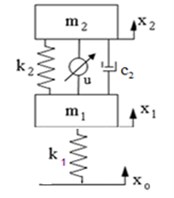
Equations of the vertical motion of the vehicle main body are as follows [16]:
where is the vertical displacement of vehicle main body, is the vertical displacement of tyre-axle mass, is the road disturbance, is the controller force. The other system parameters are given in Table 1.
If the vehicle carries unknown load and the load changes to , , . Considering the previous studies [20], uncertainties on the parameters are assumed as follows: 100 kg increase on the mass including passenger and luggage, a possible 10 % uncertainty on both stiffness and the damping of the suspension system. Hence, the controller is designed in the robustness of interval:
Considering the previous studies [11], mean value of the range of possible parameters are chosen nominal control parameters and they are given in Table 2.
Table 1Parameters of the quarter car model [20]
Sprung mass | Unsprung mass | Stiffness of the suspension | Stiffness of the tyre | Damping coefficient of suspension |
253 kg | 42 kg | 16434 N/m | 97939 N/m | 1345 N.s/m |
Table 2Nominal parameters of the quarter car model.
Sprung mass | Stiffness of the suspension | Damping coefficient of suspension |
303 kg | 16434 N/m | 1345 N.s/m |
With this choice of uncertainty parameters, the uncertainty bound is calculated as:
And thus 1649.65. Uncertainty bound separately shown in Table 3.
Other control parameters used in the simulation are as follows:
Road disturbance is given in Fig. 3 [13].
Table 3Uncertainty bound
1643.4 | 134.5 | 50 |
Fig. 3Road disturbance [13]
![Road disturbance [13]](https://static-01.extrica.com/articles/18429/18429-img4.jpg)
The controller is applied to a vehicle suspension system and the results are given in Figs. 4-10.
As seen from the Fig. 4, the sprung mass acts as ideal skyhook model as it would be given in Eq. (3) in case of the vehicle is subjected to the road disturbance and if the system faces to parametric uncertainties. The amplitudes of the vertical displacement are significantly reduced to that of the targeted dynamics which oscillates around zero amplitude. The vehicle has reached the targeted dynamics with small error values. The peak value for vertical displacement of the controlled system is nearly 0 m while it is 0.095 m in passive system. There are two main goals here. On the first hand, the targeted dynamics should be reached. On the other hand, the vertical displacements should be minimized. Both goals are achieved in this study. One can obtain from here that the applied proposed adaptive-robust control law is successfully suppressed the vertical oscillations.
Fig. 4The oscillation of the sprung mass over time
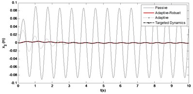
Fig. 5Dynamic manifold
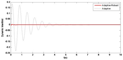
Fig. 6The vertical acceleration of sprung mass over time
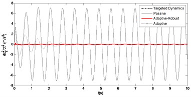
Fig. 7Suspension gap changes over time
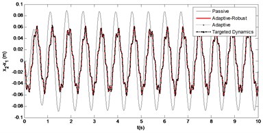
Fig. 8Controller force changes over time
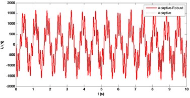
Fig. 9Frequency response of the vertical displacement
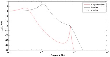
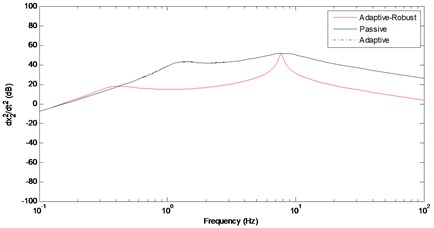
Fig. 10Frequency response of the vertical acceleration
In order to observe whether the vehicle’s vertical movement reached the targeted dynamics or not, Fig. 5 should be taken into consideration, as well. When the dynamic manifold (4) is zero, then it is said that the targeted ideal skyhook model (3) is reached. As it can be seen from the figure that sprung mass tracks the targeted dynamics with very small error. This value is sufficient.
The main criterion for a good ride comfort is to minimize the vertical acceleration as soon as possible. According to Newton’s second law, the acceleration causes the force that makes the human beings uncomfortable. It can be seen from the Fig. 6 that the acceleration is around the zero and it reaches the targeted dynamics acceleration values. The peak value of the acceleration in passive system is approximately 7.5 m/s2 while it is nearly 0 m/s2 in controlled system. This result shows that the ride comfort has been improved.
As seen from the Fig. 7, the suspension gap is decreased in active system by using the robust control law. The change of the controller force with respect to time is given in Fig. 8. The frequency responses of the vehicle main body and related acceleration are given in Figs. 9-10. As seen from the figures, the proposed controller is significantly reduced the resonance frequency of the main body. This indicates that the vehicle ride-comfort has been improved. However, there is an increase on the resonance frequency of the tyre-axle mass. Any increasing on the second peak shows that vehicle road handling is decreased while the ride-comfort is improved.
5. Conclusions
In this paper, a new approach, a new adaptive-robust model reaching control law is studied to achieve target dynamics (skyhook isolation) without reference model. Lyapunov Theory, based on the Corless-Leitmann approach [7] is used for designing the model reaching adaptive-robust control law and a uniform boundness of the manifold has been approved. The control law includes a new model reaching adaptive control and a new robust control algorithm. Development of a model reaching robust control law has not been considered before. The definition of the robust control law is similar to model reaching adaptive control law [6]. As a distinct from model reaching adaptive control law, nominal control parameters are fixed as it would be in the robust control law [11] and it is not updated in time as it would be in the model reaching adaptive control strategy [6]. In the model reaching adaptive control law, parameters and upper bounding functions are updated as a trigonometric function depending on the relative displacements, velocities and a defined manifold. Thus, according to the Lyapunov theorems, it has been concluded that when yields . This result shows that the plant achieves the target dynamics of shyhook isolation. It is possible for the plant to achieve the target dynamics fast as a result of estimation of the most appropriate values of and. As seen from the simulation results, the proposed adaptive-robust control law remarkably increases the ride comfort and decreases the motion of the main vehicle body. The numerical results also verify that the most appropriate theoretical values of the and can be estimated and the fast convergence of the plant to the target dynamics can be achieved. Application of this controller to a full vehicle system should be considered for a future study.
References
-
Alleyne A., Hedrick J. K. Nonlinear adaptive control of active suspensions. IEEE Transactions on Control Systems Technology, Vol. 3, Issue 1, 1995, p. 94-101.
-
Pan H., Sun W., Gao H., Jing X. Disturbance observer-based adaptive tracking control with actuator saturation and its application. IEEE Transactions on Automation Science and Engineering, Vol. 13, Issue 2, 2016, p. 868-875.
-
Pan H., Sun W., Gao H., Kaynak O., Alsaadi F., Hayat T. Robust adaptive control of non-linear time-delay systems with saturation constraints. IET Control Theory and Applications, Vol. 9, Issue 1, 2015, p. 103-113.
-
Sun W., Gao H., Kaynak O. Adaptive backstepping control for active suspension systems with hard constraints. IEEE/ASME Transactions on Mechatronics, Vol. 18, Issue 3, 2013, p. 1072-1079.
-
Sunwoo Y., Ceok K., Huang N. Model reference adaptive control for vehicle suspension systems. IEEE Transactions on Control Systems Technology, Vol. 38, Issue 3, 1991, p. 217-222.
-
Zuo L., Slotine J. J. E., Nayfeh S. A. Model reaching adaptive control for vibration isolation. IEEE Transactions on Control Systems Technology, Vol. 13, Issue 4, 2005, p. 611-617.
-
Corless M., Leitmann G. Continuous feedback guaranteeing uniform ultimate boundedness for uncertain dynamic systems. IEEE Transactions on Automatic Control, Vol. 26, 1981, p. 1139-1144.
-
Burkan R. Design of adaptive compensators for the control of robot manipulators robust to unknown structured and unstructured parameters. Turkish Journal of Electrical Engineering and Computer Sciences, Vol. 21, Issue 2, 2013, p. 452-469.
-
Burkan R. Modelling of bound estimation laws and robust controllers for robustness to parametric uncertainty for control of robot manipulators. Journal of Intelligent and Robotic Systems, Vol. 60, Issue 3, 2010, p. 365-394.
-
Koo K. M., Kim J. H. Robust control of robot manipulators with parametric uncertainty. IEEE Transactions on Automatic Control, Vol. 39, Issue 6, 1994, p. 1230-1233.
-
Spong M. W. On the robust control of robot manipulators. IEEE Transactions on Automatic Control, Vol. 37, Issue 11, 1992, p. 1782-1786.
-
Florin A., Ioan-Cosmin M., Liliana P. Passive suspension modeling using MATLAB, quarter-car model, input signal step type. New Technologies and Products in Machine Manufacturing Technologies, 2013, p. 258-263.
-
Ikenaga S., Lewis F. L., Campos J., Davis L. Active suspension control of ground vehicle based on a full-vehicle model. Proceedings of the 2000 American Control Conference, Vol. 6, 2000, p. 4019-4024.
-
Aggarwal M. L. Fuzzy logic control of a semi-active quarter car system. International Journal of Mechanical, Aerospace, Industrial, Mechatronic and Manufacturing Engineering, Vol. 8, Issue 1, 2014, p. 154-158.
-
Sathishkumar P., Jancirani J., John D., Manikandan S. Mathematical modelling and simulation quarter car vehicle suspension. International Journal of Innovative Research in Science, Engineering and Technology, Vol. 3, Issue 1, 2014, p. 1280-1283.
-
Chantranuwathana S., Peng H. Adaptive robust force control for vehicle active suspensions. International Journal of Adaptive Control and Signal Processing, Vol. 18, Issue 2, 2004, p. 83-102.
-
Changizi N., Rouhani M. Comparing PID and fuzzy logic control a quarter car suspension system. Journal of Mathematics and Computer Science, Vol. 2, Issue 3, 2011, p. 559-564.
-
Kaleemullah M., Faris W. Active suspension control of vehicle with uncertainties using robust controllers. International Journal of Vehicle Systems Modelling and Testing (IJVSMT), Vol. 9, Issues 3-4, 2014, p. 293-310.
-
Sun W., Zhao Z., Gao H. Saturated adaptive robust control for active suspension systems. IEEE Transactions on Industrial Electronics, Vol. 60, Issue 9, 2013, p. 3889-3896.
-
Nguyen T. T., Kim S. B. Control of active suspension system by using H∞ theory. Transaction on Control, Automation and Systems Engineering, Vol. 2, Issue 1, 2000, p. 1-6.
Cited by
About this article

