Abstract
Operational experience showed that blade related failures to be common faults in gas turbines. A review of detection and assessment techniques for blade related failures in gas turbines are presented. This paper examines the use of vibration analysis and monitoring of blade pass frequencies and its side bands for blade rubs and cracks, and wavelet analysis for blades looseness detection. Case studies of operational gas turbines used in power generation are presented. A case of severe rub from a cracked shaft (that exhibited increased vibration trend over time) showed severe harmonics of running speed during a full rub. A longitudinal crack was subsequently found on the rotor shaft. Another case study demonstrated significant increase in amplitudes associated with the blades passing frequencies with increased side band activities from stator blades and labyrinth rubs prior to shaft seizure. Actual field data and historical comparisons of vibration spectra and wavelet maps of the gas turbine are presented. Looseness in the packing pieces of blade roots are also potential problems in some gas turbine designs which are difficult to detect under field conditions. The use of wavelet analysis for simulated blades looseness in a laboratory study showed changes in wavelet maps for rotor coast down measurements suggesting potential in detection for blades looseness. Changes could not be detected from FFT spectra, coast down spectra nor were it detectable from steady state FFT and wavelet analysis.
1. Introduction
Blade related failures represent the most common fault in industrial gas turbines. This paper presents operational experience of vibration analysis for blade related failures and rubs from the blades (rotor and stator blades) as well as a supporting laboratory study with induced looseness in rotating blade assemblies. Experiences as presented here were based on work undertaken by the authors assisting plant operators of gas turbines used for power generation in Malaysia.
Past experiences of power generation plants (in Malaysia and elsewhere) showed that blade failures to be common problems. Rubs are also frequently noticed on the casing and rotor. This is consistent with experience reported in the literature that showed that blade failures are the most common fault in industrial gas turbines. Meher-Homji [1-2] cited statistics from a renowned insurance company that blade failures accounted for as much as 42 % of failures in gas turbines. In a more recent write up from this insurance group (Allianz Technology Centre AZT) [3], it was stated that statistical analysis of 714 gas turbine installation components investigated by them during the last 10 years had shown that turbine blading (14 %), compressor parts (9 %), casing (5 %), combustion chambers (5 %), rotors (5 %) and burners (3 %) had the highest damage rates.
The more common problems from turbine blading are loss parts (from foreign object damage or otherwise), cracks (blades and at the roots), rubs, loose disk coupling, deformation and erosion. Loss parts would usually result in an increased synchronous vibration response (increased amplitude and/or phase shift) and are therefore more readily detected from the increased vibration amplitude and/or phase shift of the x1 vibration vector. Cracks, looseness and rubs, unless reaching catastrophic stage, often remains undetected from overall vibration levels monitoring that are typically used in a protection system and in-plant DCS/monitoring displays. Looseness could also arise at the fir tree roots where blades are attached to the rotor shaft, and at intermediate pieces for blades attachment. Such looseness is even more difficult to detect from steady state monitoring under constant state operating conditions.
2. Vibration assessment and analysis of blade related faults
2.1. Overall vibration amplitudes
Vibration monitoring and severity assessment as a matter of common practice by plant operators (and certainly in a conventional protection system and DCS based plant information system) are traditionally based on the overall vibration amplitude. This has its merits as it is a simple direct reading without frequency analysis, and had been proven to most plant operators to be a good indicator of the machine condition. Assessment can also be made using OEM’s recommended alarm and trip limits, or standards such as ISO 10816-4: 1998 and BS 7854-4: 1998 [4]. Such severity acceptance limits are however based on the overall vibration amplitude (usually velocity). This is fairly acceptable as long as the inherent fault(s) dominates the overall vibration response. There is however an inherent inability for change to be noticed if the underlying fault(s) do not dominate the response (such as blade related faults which do not result in forcing excitation that are as significant as the unbalance response for example). The inability of the overall vibration velocity to detect an impeding failure for blade rubs and shaft seizure is demonstrated here for an actual case study.
2.2. Frequency analysis of blade related signals
Blade passing frequency (BPF) is the frequency generated in rotating machines with bladed assemblies. BPF is the rate at which the blades pass by a stationary component such as the casing. Researchers have studied the application of BPF in blade faults diagnosis since the 1970s. Mitchell [5] for example reported on relational changes in the blade passing frequency (BPF) and its harmonics for blade faults diagnosis (for pumps). The use of vibration analysis for blade faults diagnosis was also studied by others (Parge, et al. [6], amongst others). It had been shown that blade faults could be detected by observing relative changes in the BPF and its harmonics amplitude. More recent works were on the use of blade-passing profile as the fundamental parameter in novel signal analysis methods for blade faults diagnosis using wavelet analysis (Aretakis [7] for example). Lim and Leong [8] presented a method to diagnose various conditions of blade rubs in rotating machinery by analyzing the shape of the operational deflection analysis (ODS) of the rotor casing specifically at BPF frequency. Meher-Homji [1-2] commented that a considerable amount of experimental work still needs to be done to correlate blade problems with the vibration signatures, but there is little doubt that useful information could be extracted from the vibration signatures as demonstrated from the case studies presented below.
2.3. Wavelet analysis
Wavelet analysis, unlike Fourier analysis which compares the signal with sine and cosine functions, applies wavelets (pieces of waveforms) to measure the data samples. The resulting wavelet analysis not only gives frequency information but also provides the corresponding time information. Wavelet transforms have advantages over traditional Fourier transforms for representing functions that have discontinuities and sharp peaks, and for accurately deconstructing and reconstructing finite, non-periodic and/or non-stationary signals. There are numerous wavelet families available for wavelet analysis of a signal. The selection of the wavelet families for signal analysis depends on its characteristics of that family such as the shape of the wavelet: symmetry, the number of vanishing moments, and the regularity. Wavelet family is important to the pattern of the wavelet map representing the signal considered. Wavelet analysis method is widely used to detect rubbing in rotating machinery. For example, Peng [9] conducted a study to determine the effectiveness of using the conventional scalograms as compared to the reassigned scalograms for the detection of rubbing. He found that when rubbing occurred, its rubbing impacts could lead to an increase in vibration amplitude at high frequency region. In his other paper [10], wavelet analysis was used as a mean to extract important features related to impact induced by rubbing. Wang [11] proposed a method to determine the location of rubbing in a rotor bearing system based on acoustics emission and wavelet analysis.
Field experience of BPFs and its sidebands as well as wavelet analysis of blade passing frequencies for operational gas turbines with rubs are presented in this paper. Coiflet (level 5) wavelet family was chosen for wavelet analysis of the field and laboratory study here because the wavelet map plotted with it was more symmetrical.
2.4. Other methods
There are published literatures on alternative methods for detection and assessment of blade related faults. Notable work had been reported by Mathioudakis et al. [12-13] on fault identification of gas turbine and compressor blade faults correlated to pressure fields. It was shown that the unsteady pressure field provided a clearer picture of the blade faults than the conventional vibration information. Using non-parametric identification methods, acceleration outputs were correlated to unsteady pressure measurements taken by fast response transducers at the inner surface of the compressor casing. It was demonstrated that information could be deduced from casing measurements without intrusive measurements in the inner working sections. There is also potential for performance related indicators to be used in condition monitoring.
3. Manifestation of Severe rub from cracked shaft
This case study was for a 110 MW in a gas turbine turbo-generation set in a Malaysian power plant. Fig. 1 illustrates a schematic diagram of the 110 MW gas turbine turbo-generation set. Steady but significant increases in the OEM’s casing overall vibration levels were noted from the monitoring system fitted for the unit. Initial concerns and diagnosis by the plant and vendor focused on probable rotor unbalance, which included trim balancing works in an attempt to reduce the vibrations. Such efforts however did not yield meaningful reduction. (This was several months before the cracked shaft was detected).
Fig. 1Schematic diagram of a 110 MW gas turbine turbo-generation set
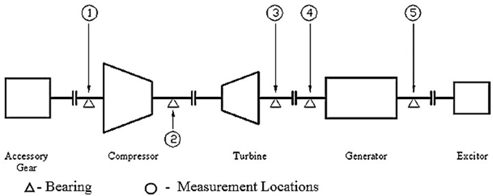
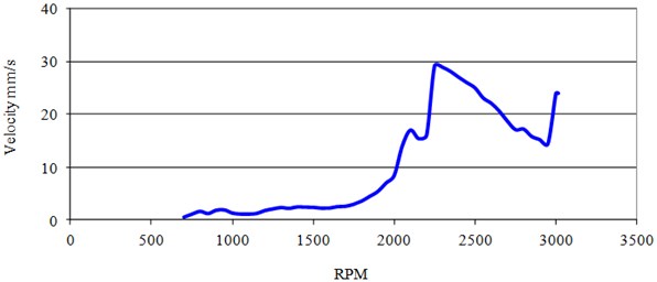
Fig. 2 shows trends of the x1 synchronous component for bearing casings in vertical direction over a month time span leading to the impending failure. Bearing (Brg.) No. 1 (compressor non-drive end), No. 3 (turbine drive end) showed marked increase over the latter two weeks period. Vibration levels in the four months period prior to this were less than 1 mm/s for bearings No. 1 and 3, and 3.3 mm/s for bearing No. 5 (generator non-drive end). The alarm limit was 12 mm/s and trip level at 25 mm/s (0-Pk). The synchronous amplitude and phase angle plots with speed (RPM) during the machine run up vibration investigation are shown in Fig. 3.
Fig. 2Casing overall vibration levels as a cracked shaft was developing
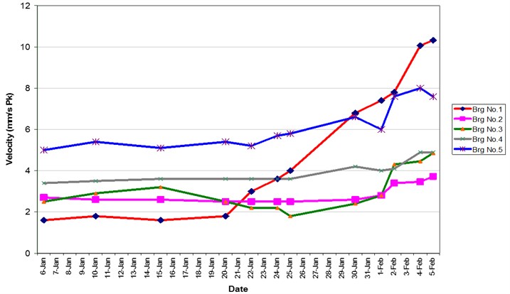
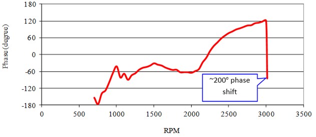
Fig. 3Run up vibration amplitude (x1 RPM) and phase angles vs. RPM
a)
b)
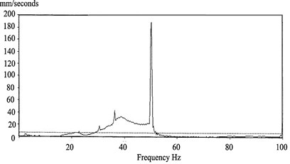
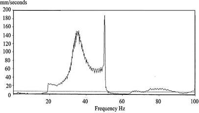
The vibration spectra during the run up past the first critical speed until the second critical speed were dominated by the synchronous x1 RPM component (see Fig. 4a). Vibration amplitudes however increased substantially as the second critical of 2280 rpm was approached. At this stage, high harmonics of x2, x3 and x4 rpm were noted (Fig. 4b). This suggested a rotor rub at the second critical had occurred due to excessive amplification at the second critical speed. After passing the second critical, vibration levels dropped with less prominent harmonic components. This suggested the rub being relieved at this point in time. As the unit approached full speed no load (FSNL) conditions at ~3000 rpm vibration levels were below the trip limit.
The vibration spectrum at speeds before and just at full speed no load is shown in Fig. 2. While settling at full speed (at marginal over speed to 3008 rpm) an instantaneous increase of vibration levels, most severe at the outboard (non-drive end) compressor bearing with peak velocity levels of up to 194 mm/s, occurred. This was accompanied by a phase shift of approximately 200º. A manual trip of the turbine was initiated.
During the coast down, the dynamic amplification at the second critical was more severe as compared to the run up; Fig. 5a and b. The vibration response in the vertical directions was significantly higher than response in the horizontal direction particularly in the compressor NDE (Brg. 1) and turbine DE bearings (Brg. 3). A cracked shaft and/or thermally bent shaft were suspected to the root cause of the increasing vibrations particularly at the compressor bearing. A full rub was thought to have occurred as the unit passes through the second critical, with further development of a thermal bent shaft aggravating the problem which explained the severe excursion.
A subsequent run up investigation of the gas turbine was initiated by the plant with the generator uncoupled to isolate any fault from the generator. This run-up re-confirmed higher response in the vertical directions than the horizontal, with highest response at the compressor bearing. The unit was removed for an inspection where a 100 mm longitudinal crack was found in the compressor section, together with signs of severe rubs on the compressor blades. This resulted in a downtime of more than 8 months awaiting a replacement shaft at a time when there was almost no spare capacity in the national grid.
Fig. 4Vibration spectrum during run up (before and rub)
a) During no load run up (at 2826 rpm)
b) During run up no load (3008 rpm) with rub
Fig. 5Peak hold spectra during run up and coast down after a rub (bearing 1 vertical)
a) During run up
b) During coast down
4. Experience of rub from stator blades and labyrinths
Four gas turbines each rated 100 MW were used in a combined cycle plant. The turbines had been in service for several years, but had no baseline vibration spectrum taken during new conditions. Detailed vibration spectra at base load condition were obtained on a particular unit (GT4) before a scheduled overhaul. The measurements were then correlated to the blades’ condition during overhaul inspections. During the overhaul, minor maintenance works on the compressor blades were conducted. No major defects were found on rotor and stator blades. Measurements immediately after the overhaul were undertaken to be used as baseline information for blade faults diagnosis based on the assumption that all blades in the unit were in good condition immediately after the overhaul. Periodic monitoring was undertaken over several months. Comparison of vibration spectra of GT4 with three other operating units was also undertaken. Assessment of BPF and sidebands with statistical analysis to determine standard deviations under normal conditions were undertaken to establish alarm limits for blade faults diagnosis.
Three months of operation after the overhaul, rubbing like noise was audible from the compressor section during the coast down of GT4. Under steady state operating conditions (with load and full speed no load), this noise was inaudible. Plant personnel also noted that the coast down time of the unit under load conditions to stand still state reduced significantly. Under prior normal conditions, the coast down time was approximately four hours which then reduced to approximately 20 minutes instead. A vibration investigation was initiated.
Fig. 6Acceleration spectrum as measured on bearing 6 months and 1 day before shaft seizure
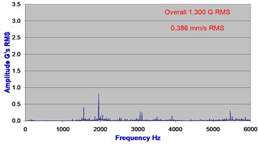
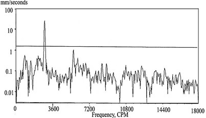
a) Axial direction: 6 months before seizure
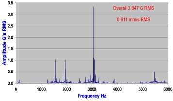
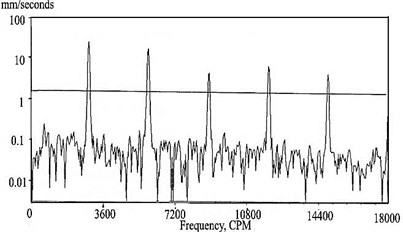
b) Axial direction: 1 day before seizure
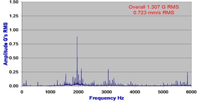
c) Vertical direction: 6 months before seizure
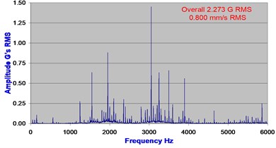
d) Vertical direction: 1 day before seizure
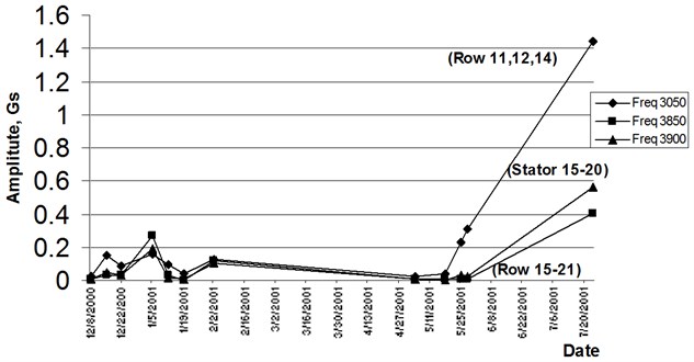
Typical vibration spectra on the generator drive end bearing casing undertaken six months earlier are given in Fig. 6a and c. Vibration spectra at the same location under suspected fault condition are given in Fig. 6b and d. Comparison of the spectrum showed distinct increase in specific blade passing frequencies (BPF), and with increased side bands of the BPF at intervals of the synchronous rpm. BPF at 3050 Hz, 3250 Hz, 3850 Hz and 3900 Hz were exceptionally high in vertical axis. Measurements in axial axis showed that the BPF of 3050 Hz was extraordinary high. Multiple harmonics of 3400 Hz, 3500 Hz, and 3600 Hz were also noticeable. The BPF of 3050 Hz (corresponding to compressor blades row 11, 12 and 14) in the vertical and axial directions showed increase with standard deviations as high as 13 times. For BPF of 3250 Hz (row 13), an equally high amplitude exceeding 28x standard deviations was noted. Other BPF of 3850 Hz (row 15-21) and 3900 Hz (stator blades row 15-20) also increased above 7x standard deviation. Trends of the BPFs are shown in Fig. 7.
Correlated with the physical evidence of reduced coast down time (which was obviously a strong indicator of increased friction i.e. rub) and with an audible rubbing sound, it was suspected that there were blade rubs. It should in fact be concluded with sufficient confidence that blade faults had occurred in the latter rows of compressor section of GT4.
Fig. 7Trending of selected blade pass frequencies
Despite the above concerns on the unit, it was decided by the National Grid administrators that the turbine was to remain in operation since the overall vibration levels (in velocity mm/s) as recorded in the DCS were substantially below OEM’s alarm limits. The rotor of GT4 seized up coincidently the day after the measurement during its coast down. The unit could not be turned until the subsequent day after cooling to cold conditions. Due to load demands from the electricity grid, the unit was brought back to service. This inevitably resulted in a recurring shaft seizure during coast down.
The extremely high BPF implied that the clearance between the rotor with stator and casing on these rows had been reduced. This was consistent with published works of Kubiak et al. [14] that reported that if the BPF had increased significantly in the vibration spectrum, blade rubbing could probably be present. The multiple harmonics noticed around 3400 Hz to 3600 Hz (which is not the BPF) in the vibration spectrums provided further evidence of rubbing. The rubbing between the rotor and stationary components could generate excessive localized heat and potentially causing the rotor to bow. A bowed rotor could further increase the rubbing. This explained the rotor seizure.
Extending the BPF analysis for the blade rubs, wavelet maps were also derived using time series data of the same measurements. The wavelet maps for the case prior (to fully developed fault) and during rub conditions are shown in Fig. 8 below. The wavelet maps under blade rub conditions did demonstrate noticeable changes.
An outage was initiated for a physical inspection. It was found that some compressor stator blades particularly at row 20 and row 21 at the upper part of compressor casing showed traces of rub marks at the tip of the blades. This finding was in good agreement with the assessment that the higher BPFs seen on the vibration spectrum were due to the rubbing in the unit. Further inspections confirmed more severe and underlying faults on labyrinth glands. The labyrinth glands immediately after the last row of compressor blades experienced a severe rub against the rotor shaft. The rubbing was approximately 3 mm in depth which could have reduced the efficiency of the gas turbine due to the pressure leakage in the compressor.
Root cause analysis of the rubbing in the unit suggested that rotor eccentricity was the likely reason of the rub. Radial blade rubs are a more common type of blade tip rubbing caused by excessive differential expansion of the rotor and casing components during transient event (shut down, emergency trip, start up). Neither of these anticipated conditions was found during the inspection. There was a suggestion by the OEM that the root cause could be due to the compressor casing distortion. Casing distortion could occur due to the non-uniform insulation on the compressor casing. Remedial works on the unit was carried out to improve the insulation on the compressor casing. The unit was put into service again although the root cause of the rubbing was not conclusively identified.
Fig. 8Local wavelet at time of increased BPFs leading up to shaft seizure
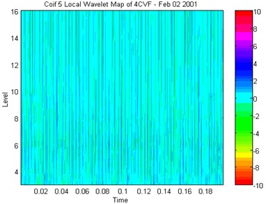
a) Baseline no fault (vertical)
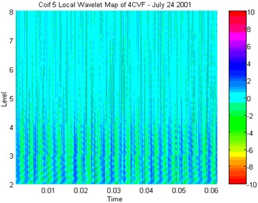
b) 1 day before seizure (vertical)
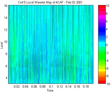
c) Baseline no fault (axial)
d) 1 day before seizure (axial)
Important lessons learned showed that overall vibration velocity amplitudes recorded no significant change (even up to the day before rotor seizure casing vibration was less than 2 mm/s RMS). In accordance to internationally accepted vibration severity criteria were deemed “good”. Overall vibration acceleration (g) however indicated appreciable increase (from 1.3 g to 3.8 g RMS in the axial direction). The difference in sensitivity of the acceleration parameter as compared to velocity was inherent because the velocity parameter was biased towards the lower frequency range (x1 RPM and lower order harmonics; remembering that resulted in amplitudes scaled down by 2).
Plant (and National Grid administrators) decisions were made on assessment of severity alarms based on overall velocity levels which showed that levels were not approaching limits of concern – be it OEM’s alarm limits (12 mm/s) and recommendations of ISO 10816-4: 1998, BS 7854-4: 1998 for gas turbines (at 9.3 mm/s and 14.7 mm/s). These limits appeared to be more suitable for synchronous (unbalance and other x1 RPM and low order harmonics related) faults that dominate overall amplitudes.
Detection of potential concerns from blade related faults and rubs required analysis of BPFs and sidebands generated. In this case study, the axial vibration spectra showed a more distinct change as compared to vertical spectra (although changes in vertical were also evident). There were no significant changes in the synchronous x1 RPM (and lower harmonics of RPM) which explained insignificant change in the overall vibration velocity levels. Trending of the BPFs showed changes up to 28x standard deviations.
Wavelet analysis while showing changes in the wavelet maps required some degree of interpretation of the changes in periodicity and intensity levels. Operational and collaborating evidence of decreased time in coast down was also shown to be a strong indicator (associated with increased friction), and must not be ignored. Anyone ignoring it does so with peril.
5. Wavelet analysis and FFTs for simulated loose blades
While vibration based detection of blade rubs may be detectable using frequency analysis, especially with acceleration based FFTs of the BPFs (but not with overall vibration amplitudes and velocity parameters), loose blades are even more difficult and pervasive to detect under field conditions for operational machines. This section of the paper presents some findings of a laboratory study of detection of loose blades using wavelet analysis that merit consideration for use on operational machines.
Experimental studies (see the experimental rig in Fig. 9) were undertaken to simulate loose blades condition (at the attachment points that typically replicates conditions in some gas turbines) to provide a better understanding on characteristics of loose blades under different operating conditions. Details of the study and test conditions are given elsewhere (Lim and Leong [15]). Test configurations included baseline no fault conditions, single and multiple loose blades, and random loose blades with varying degrees of looseness. Results of the experimental study under various controlled conditions showed that loose blades were undetectable under steady state operating conditions (constant speed) presumably due to centrifugal action forcing the loose blades into a “locked position”. It was during rotor coast downs that looseness in the blades was detectable based on the series of impact signals generated by the loose blades exciting natural frequencies of the rotor system. Results from the coast down condition showed that wavelet analysis was more sensitive and effective than Fourier analysis for loose blades detection. The severity, number and configuration of the loose blades could be potentially estimated based on the pattern of the coast down wavelet map.
Fig. 9Photograph showing test rig with blade assembly and intermediate locking pieces
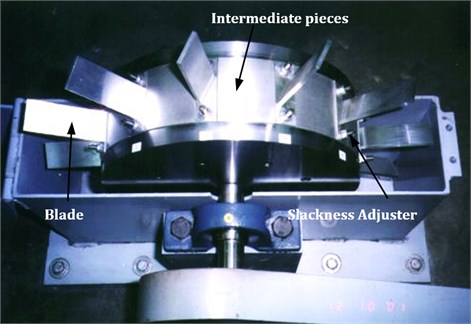
Fig. 10Coast down FFTs without and with loose blades
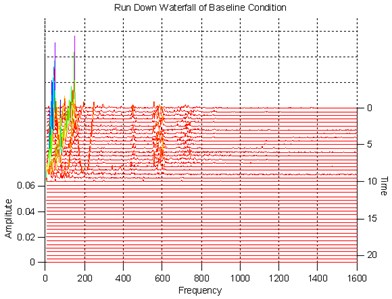
a) Baseline no fault
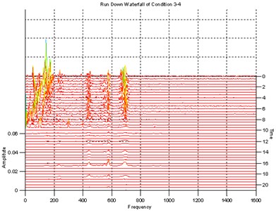
b) With loose blades
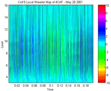
Fig. 11Wavelet maps without and with loose blades
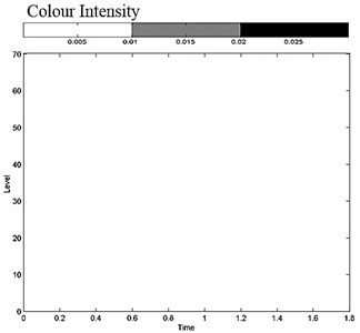
a) Baseline no fault
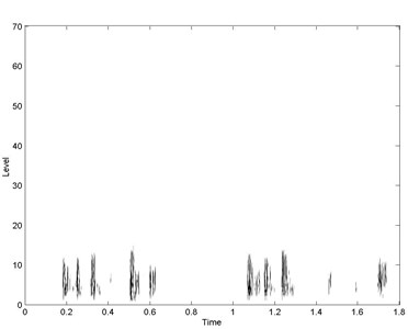
b) With loose blades
Fig. 10 shows a cascade plot of FFTs spectra as the rotor coast down from operating speed to stationary conditions. The plots showed no discernable differences that suggested any abnormality in the vibration response between no fault conditions with the case having induced blade looseness. In the baseline condition (no fault), the coast down wavelet map was clean, Fig. 11(a). Fault conditions with blade looseness showed distinct changes in the coast down wavelet, Fig. 11(b). Looseness severity, the number of loose blades, as well as configuration of the loose blades governed the time duration of consecutive impacts and severity level of the wavelet maps. This finding was in good agreement with the finding of Aretakis et al [7] that the wavelet analysis allows local features and hidden details of a signal to be identified that may make it useful for condition monitoring when detection of small dynamic changes is important.
6. Conclusions
Overall vibration velocity amplitudes while sufficient for common unbalance response monitoring were found to be inadequate to detection of blade related faults in operational gas turbines. Blades passing frequencies and its sidebands were found to showed changes for blade rubs detection. Wavelet analysis for rotor coast down showed changes with simulated blade looseness in a laboratory study that merits consideration for use in operational machines. Such looseness was not readily detected from the FFT coast down spectra nor were it detectable from steady state FFT and wavelet analysis.
References
-
Meher-Homji C. B. Blading Vibration and Failures in Gas Turbines: Part C – Detection and Troubleshooting. ASME, No. 95-GT-420, 1995.
-
Meher-Homji C. B. Blading Vibration and Failures in Gas Turbines: Part D – Case Studies. ASME, No. 95-GT-421, 1995.
-
Allianz Center for Technology. Product Service Information 1/00. www.en.allianz-azt.com (Information / Damage Analysis).
-
ISO 10816-4: 1978 / BS 7854-4: 1978. Mechanical Vibration – Evaluation of Machine Vibration by Measurements on Non-Rotating Parts – Part 4: Gas Turbine Driven Sets Excluding Aircraft Derivatives.
-
Mitchell J. Examination of pump cavitation, gear mesh and blade performance using external vibration characteristics. Proceedings of the 4th Turbomachinery Symposium, Texas A&M University, 1975, p. 39-45.
-
Parge P. Non-intrusive vibration monitoring for turbine blade reliability. Proceedings of Second International Machinery Monitoring and Diagnostic Conference, Los Angeles, 1990, p. 435-446.
-
Aretakis N., Mathioudakis K. Wavelet analysis for gas turbine fault diagnostics. ASME Journal of Engineering for Gas Turbine and Power, Vol. 119, 1997, p. 870-876.
-
Lim Meng Hee, Leong M. S. Experimental study of dynamic responses of casing deflection profile for blade rubbing classification. Journal of Vibroengineering, Vol. 14, Issue 4, 2012, p. 1668-1680.
-
Peng Z. K., Chu F., Tse P. W. Detection of the rubbing-caused impacts for rotor–stator fault diagnosis using reassigned scalogram. Mechanical Systems and Signal Processing, Vol. 19, Issue 2, 2005, p. 391-409.
-
Peng Z. K., He Y., Lu Q., Chu F. Feature extraction of the rub-impact rotor system by means of wavelet analysis. Journal of Sound and Vibration, Vol. 259, Issue 4, 2003, p. 1000-1010.
-
Wang Q., Chu F. Experimental determination of the rubbing location by means of acoustic emission and wavelet transform. Journal of Sound and Vibration, Vol. 248, Issue 1, 2001, p. 91-103.
-
Mathioudakis K., Loukis E., Papailiou K. D. Casing vibration and gas turbine operating conditions. ASME Journal of Eng. for Gas Turbine and Power, Vol. 112, 1990, p. 478-485.
-
Mathioudakis K., Papathanasiou A., Loukis E., Papailiou K. D. Fast response wall pressure as a means of gas turbine blade fault identification. ASME Journal of Engineering for Gas Turbine and Power, Vol. 113, 1991, p. 269-275.
-
Kubiak J., Gonzalez G., Garcia G., Urquiza B. Hybrid fault pattern for the diagnosis of gas turbine component degradation. International Joint Power Generation Conference, New Orleans, No. PWR-19112, 2001.
-
Lim M. H., Leong M. S. Diagnosis for loose blades in gas turbines using wavelet analysis. ASME Journal of Engineering for Gas Turbine and Power, Vol. 127, Issue 1, 2005, p. 314-322.
About this article

This work is supported by Exploratory Research Grant Scheme (ERGS) (R.K130000.7840.4L089) as financed by the Ministry of Education Malaysia.
