Abstract
The possibilities of vibration diagnostics of high-speed equipment units with gas turbine engines are analyzed under the restrictions determined by the high level of vibration excited by air and gas flows and mutual instability of rotation frequencies of the power turbine and compressor turbines. The approaches to the organization of their diagnosis by vibration signal, taking into account these restrictions are discussed. The first approach is designed for the use of special methods of measurement and analysis of vibration spectra in the operating mode, the second approach is designed for its bench diagnostics when the equipment is rotating by an external drive with a reduced and stable frequency and, accordingly, with a low level of flow noise and without combustion.
1. Introduction
Modern power units for small electric power industry and transport are often created on the basis on high-speed gas turbine engines using gears for further load transmission and distribution. Vibration diagnostics is one of the most important areas of machine condition monitoring and forecasting for such units [1-3], but it is hampered by a high level of high-speed gas turbine engines random vibration created by the combustion process, as well as by the flow of air and combustion products, “masking” the vibration of many components that determine the reliability and life of the equipment unit [3-5]. Besides this the gas turbine engine includes not only large components – the main sources of machine vibration such as rotors and impellers of compressors and power turbines, but also less loaded units for starting the unit, its lubrication, energy removal for auxiliary needs and others, driven in rotation through gears. In addition, in such units, there are numerous components of vibration; the source of which is not only the gas turbine engine, but also the actuators loaded on it, in particular the power reducer, the electric generator and others. All this leads to a large saturation of the vibration signal harmonic components that characterize the state of the various nodes, and dramatically complicates its analysis.
To solve the diagnostic problems under the conditions of high-level random vibration, excited by gas flows, and periodic vibration from multiple sources, it is necessary to use the means of signals spectral analysis with high frequency resolution and dynamic range. But the use of such means is hampered by the limited speed stability of the non-rigidly coupled shafts of the gas turbine engine, each of which has its own means of automatic speed stabilization. General and mutual instability of rotation frequencies without the use of special processing algorithms, in turn, leads to distortion of harmonic components and the inability to determine their parameters. The following are the description of main results obtained by the authors in the process of developing diagnostic tools for units with gas turbine engines. The above problems were solved.
2. Problem solving experience
Currently, for general machine condition control of the gas turbine engines, broadband vibration monitoring is usually used, which can be supplemented by vibration control in narrow frequency bands that capture the speed of the main shafts of the engine. Such vibration measurements in specially selected control points provide detection of dangerous changes in the loaded shafts condition, accompanied by an increase in their unbalance, as well as the condition for the impellers of the compressor and the power turbine, that affect the properties of the gas flow, but not always make it possible to detect deterioration of the equipment unit due to defects in other components, especially rolling element bearings.
For timely diagnosis of bearings, as well as other critical components of the equipment unit, which are the source of harmonic components of vibration, it is necessary to measure narrow-band vibration spectra, significantly increasing their frequency resolution, and optimize the location points of its control. Such approach to vibration diagnostics of equipment units with a gas turbine engine can be easily implemented when there is a high stability of the shaft rotation frequency of the diagnosed unit because in this case it does not require the application of more sophisticated methods of analysis and allows to automate the processing of the spectra. Stable speed can be achieved, for example, in bench conditions by rotating each of the mechanically unbound shafts from an external drive. There are also units with gas turbine engines, the speed of which has a high degree of stability during operation. These include the electricity production installations where a single-shaft gas turbine engine with a common shaft of the compressor and the power turbine has a rigid connection with the input shaft of the reducer, and the reducer – a rigid connection with the shaft of the electric generator. Since the output voltage of the generator is synchronized with the industrial network, the unit has a stable speed, which makes it possible to use high resolution and algorithms for the accumulation and averaging of spectra in the spectral analysis of vibration.
The first stationary system, which was developed with the participation of the authors, for vibration diagnostics of the unit with a gas turbine engine was installed on such a unit (gas turbine engine Taurus-70, the rotation speed of 15,000 rpm, the rotation speed of the generator 1500 rpm, the frequency of the electrical network 50 Hz). The relative “simplicity” of the vibration spectrum was also determined by the use of sliding bearings in this unit. All this made it possible to use for high-speed equipment unit with a high level of vibration of aerodynamic origin the diagnostics of a standard algorithms for automated vibration diagnostics, used for the diagnostics of less high-speed equipment, such as pumps, fans and others. In particular, vibration spectra with a frequency resolution of 1 Hz, up to a frequency of 25600 Hz, averaged for 10-20 seconds, were measured to analyze the vibration of this equipment unit.
Fig. 1A vibration spectrum of the planetary gearbox with the signs of wear of the crown teeth – increase of the level of harmonics of rotations output shaft (k*Frot) whose frequencies is close to 1/3 gearmesh frequency (Fgmf), measured for a month prior to the triggering of a regular means of emergency protection
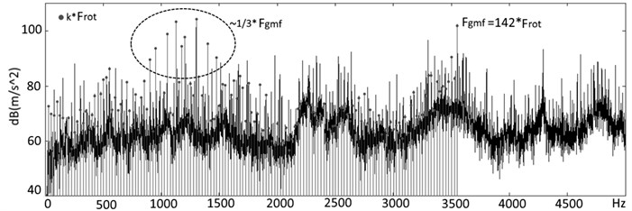
Despite the saturated spectral composition of the equipment unit vibration (see Fig. 1), measured at several points on the stationary parts of the engine, planetary gearbox and synchronous four-pole generator, the system provided the allocation of the main diagnostic features of typical defects of the engine itself, gearbox, generator and general lubrication system.
Three years of diagnostic system operation showed the possibility of defects detection and identification in the equipment units of the installation long (a month) before the real danger to continue its operation. In total, three defects were identified that required the intervention of maintenance services.
When trying to use standard algorithms for processing the vibration spectra of gas-pumping units with gas turbine engines with rolling element bearings by increasing the frequency resolution in the spectrum, it turned out that it was impossible to increase it to the required value in 1 Hz. And such a resolution in the high-frequency part of the vibration spectrum is necessary to identify defects in the impellers and gears by the harmonics of blade-pass and gearmesh frequency. But in the real spectra due to the instability of the rotation frequencies of the gas turbine engine shafts, the corresponding components of the vibration of the unit were distorted and blurred, so the processing of the averaged spectra gave incorrect results.
Thus, the results of monitoring the instantaneous values of the speeds of the compressor turbine and the power turbine of the gas pumping unit for 10 seconds show (Fig. 2) that the own control system keeps the frequency in the range of ±0.2 % of the average value. At the same time, when measuring vibration for the subsequent analysis of harmonic components in the area of blade-pass and gearmesh frequencies, it is necessary to stabilize the speed by an order more accurately.
Fig. 2Fluctuations of rotation frequency of the turbine compressor (Ftk) and power turbine (Fpt) of a gas turbine engine
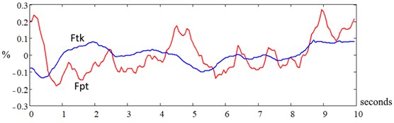
Fig. 3a) Vibration spectra of the gas turbine engine, measured with four and b) one averaging and once, with frequency resolution df = 1 Hz
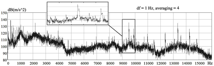
a)
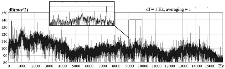
b)
As a result, the spectra, measured with a resolution of 1 Hz (Fig. 3(a)), after accumulation with averaging, cannot be used for processing harmonic components at high frequencies. The accumulation of spectra with their averaging, necessary to reduce the statistical spread of random vibration components, leads to distortion of the harmonic components of the spectrum with the loss of accurate data on their frequency and level.
Since the accuracy of speed stabilization on existing engines cannot be significantly improved, the only way to solve this problem is to create special methods for signal processing. The first one is to use the order spectra, the second is to develop special methods for processing vibration spectra with a high level of random components, measured once during short intervals with relatively stable shaft rotation speed of the equipment unit.
Measurement of order spectra when the changes of the rotation frequency of the shafts of one equipment unit is not smooth and differently directed do not always produce practically acceptable results. Therefore, the main direction of solving the problem can be considered to be the improvement of methods for processing vibration spectra measured in those short intervals of time, at least 1 second, when both independently adjustable compressor and power turbine shafts have practicably stable speeds. To do this, it was necessary to implement algorithms for finding the appropriate interval and methods of processing the measured without averaging narrow-band vibration spectra with a high level of random components and limited frequency fluctuations of harmonic components, ensuring high accuracy of determining their amplitudes and frequencies.
As a result of the research a method was chosen that works effectively in the processing of a single (without averaging) spectra of the vibration when there are fluctuations of rotation frequency, taking into account the shape of the harmonic signal spectrum when using the Fourier transform with a Hanning window [6]. In accordance with this method, firstly areas of the spectrum in which the measurement results are above the threshold of the smoothed value of the random components of vibration (background) are selected, then the approximation by a second order polynomial is used [7], the top of which determines the frequency and amplitude of the harmonic, also estimated are the width of the harmonic as the distance between the equation roots, read more here [8]. The usage of symmetric about the -axis approximation function, in contrast to the common nondestructive testing methods [2, 9], allows to accurately determine the average frequency harmonics when there are fluctuations of its frequency as a coordinate on the -axis when the line widens remains practically unchanged. The harmonic level is improved by an amendment that takes into account the width of the line. The use of the considered processing algorithm has dramatically increased the accuracy of determining the frequency and level of harmonics, as well as reduced the errors of combining harmonics into harmonic series when there is an instability of the speed and high saturation of the spectra by harmonic components.
There is another group of problems in high-speed gas turbine engines diagnostics. It occurs when in the rotation units of compressors or power turbines are installed rolling element bearings. In this case the problem not always can be solved even with high-speed stability. That is because in nominal modes of operation due to the high level of random vibration excited by combustion and flow, no pulse vibration excited by shocks in defective bearings can be detected against its background, even if the fault has already reached a severe level. This makes it impossible to use effective and proven methods for bearing condition diagnostics based on their high frequency and ultrasonic vibration analysis, such as the shock pulse method [10] and the envelope spectrum analysis [11, 12]. Therefore, almost the only way to control the appearance of bearing defects and estimate their severity is the detection of harmonic components in the motor vibration spectra at bearing frequencies.
To solve this problem, it is not enough to ensure the stability of the rotation frequency of the compressor shafts and the power turbine, we also need a stable (static or rotating) load on each rolling bearing of the unit. In the nominal mode of operation of the unit, such a load is only in angular contact bearings (axial) and in mechanical gears mainly on satellite bearings. At the same time, in many high-speed turbines and axial compressors, due to the radial asymmetry of the aerodynamic forces acting on the impellers and the shaft, the load on the radial bearings is unstable. For this reason, the traditional approach to the diagnosis of rolling bearings under unstable load is ineffective.
Taking into account the above, the diagnosis of gas turbine engines with forced rotation of its shafts from an external drive at low speeds, when the value of gas dynamic forces and, accordingly, the level of the associated background vibration are sharply reduced, gives practical benefit. In this mode, the radial bearings of the power shafts are subjected to the dominant static load – the gravity of the rotor, which makes it possible to diagnose the bearings of the power shafts of the unit by traditional methods.
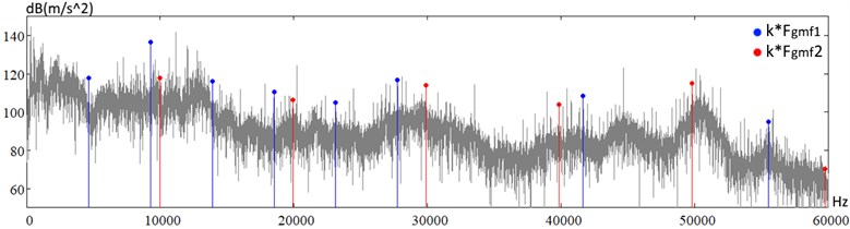
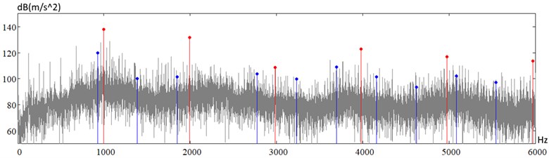
For example, in Fig. 4 vibration spectra of the similar gas turbine engines measured at the same control point in the nominal operation mode and on the stand, with forced rotation from external driver at a frequency 10 times lower are given.
Fig. 4Vibration Spectra of the gas turbine engine a) in the nominal operating mode, measured in the frequency range up to 60 kHz (upper spectrum) and b) at forced by external drive rotation with a frequency 10 times lower, measured in the frequency range up to 6 kHz (lower spectrum), Fgmf1 and Fgmf2 – gearmesh frequencies in the driver box
a)
b)
Analysis of the spectra shows that the level of random vibration excited by the flow, when the rotor is forced to rotate from an external driver, decreases in the low-frequency part of the spectrum by more than 100 times, while the level of many harmonic components, responsible for different defects, are deceased by less than 10 times. This opens up enhanced opportunities for detecting the defects in rolling element bearings and gear mesh at an early stage of their development by vibration of the stationary parts of the equipment unit.
3. Conclusions
1) For machine condition monitoring of the equipment with gas turbine engines in nominal operating modes, not all standard methods of vibration diagnostics of rotary machines are applicable due to the high level of vibration excited by combustion and gas flows.
2) The vibration diagnostics efficiency of such equipment can be improved by either using non-standard methods of processing the non-averaged vibration spectra, measured in nominal modes of operation, or carrying out diagnostics on the reduced frequency of rotation of the equipment or mechanically disconnected shafts during rotation from an external drive.
References
-
Mitchell J. S. From vibration measurements to condition based maintenance. seventy years of continuous. Sound and Vibration, Vol. 41, 2007, p. 62-78.
-
Randall R. B. Vibration-Based Condition Monitoring. John Wiley and Sons, Chichester, 2011.
-
Kiselev K.V., Epishev N. I. Diagnosis of Gas Turbine Engines and Their Components by Thermogasdynamic and Vibroacoustic Parameters. Samara State Aerospace University, Samara, 2007.
-
Balitskiy F. Y., Barkov A. V., Barkova N. A. Nondestructive Testing: Reference Book in 7 Volumes. Volume 7, Book 2, Vibrodiagnoics. Mashinostroenie (Engineering), Moscow, 2005.
-
Biryukov P. B., Kiselev Y. V. Vibration diagnostics of gas-turbine engines rotor bearings using the cold cranking. Works of the Samara Scientific Center of the RAS, Vol. 18, Issue 2, 2016, p. 153-157.
-
Randall R. B. Frequency Analysis. Bruel and Kjaer, Naerum, 1987.
-
Gasior M., Gonzalez J. L. Improving FFT frequency measurement resolution by parabolic and gaussian spectrum interpolation. AIP Conference Proceedings, Vol. 732, 2004, p. 276.
-
Grishchenko D. Automatic processing of narrow band vibration spectra of marine rotating equipment with the purpose to determine the parameters that are informative for the diagnostics. Marine Intelligent Technologies, Vol. 34, 2016, p. 8-13.
-
Harris C. M., Piersol A. G. Harris’ Shock and Vibration Handbook. МсGrаw-Нill Professional, 2002.
-
Sohoel E. O. Shock Pulses measure lube film thickness. Industrial Lubrication and Tribology, Vol. 37, 1985, p. 8-12.
-
Barkov A., Barkova N., Mitchell J. Condition assessment and life prediction of rolling element bearing. Sound and Vibration, Vol. 6, 1995, p. 10-17.
-
Robinson J. C., Canada R. G., Piety K. R. PeakVue analysis – new methodology for bearing fault detection. Sound and Vibration, Vol. 30, 1996, p. 22-25.
Cited by
About this article

