Abstract
This article discusses a vibrodiagnostic system designed for the prototypical microturbine operating in an ORC-based power plant with an electrical capacity of around 100 kW. The first part of the article is devoted to the numerical analysis of the microturbine, which was conducted with taking into account the fact that the asynchronous electro-generator is connected to the microturbine shaft by a reduction gear. Based on the results of the analysis, the diagnostic system dedicated for the microturbine has also been developed. The second part of the article presents a vibrodiagnostic system in detail. The system with a dedicated measuring and monitoring software (developed using the LabVIEW programming environment) was described. The developed solution enables not only constant monitoring of the test object, but also protects the microturbine against propagation of damage and failure.
1. Introduction
Nowadays, in modern power systems, a significant role in small-scale electric power generation is played by microturbines [1, 2]. Most often, these are machines with power of no more than 1 MW. In power microturbines, high-speed rotors are used. Their blades are relatively small, which allows to achieve high efficiencies at low flow rates of the working medium. At high rotational speeds (reaching up to several hundred thousand rpm), it is required to use advanced, unconventional bearing systems such as magnetic [3], foil [4, 5], gas [6] bearings or ones lubricated with a low-boiling medium [7]. Apart from good dynamic properties of the rotor, bearing systems must ensure high durability and reliability enabling operation of microturbines without constant technical supervision. Thanks to their small size and lower temperatures, microturbines do not require observance of startup procedures as restrictive as in the case of large power turbines [8-10]. Also, due to small turbine blades, there are no dynamic problems which normally affect machines used in commercial power engineering [11]. Microturbines are susceptible to different dynamic problems resulting from: high rotational speeds, the broad range of nominal speeds, low weight and stiffness of casings as well as whippy and lightweight support structures. This article describes the research carried out on a real object using a dedicated vibration based diagnostic system.
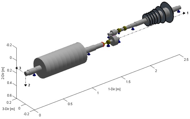
The subject of diagnostic tests was a seven-stage axial microturbine which was designed and constructed at the Institute of Fluid Flow Machinery, Polish Academy of Sciences in Gdansk. Fig. 1 presents a diagram of the microturbine rotor. Fig. 2 shows the assembly consisting of microturbine and generator rotors coupled using a belt gear. The target electric power of the turbine set will be ca. 100 kW. This machine is a prototypical solution and was built in order to conduct laboratory tests.
Fig. 1Diagram of the rotor of the axial-flow microturbine
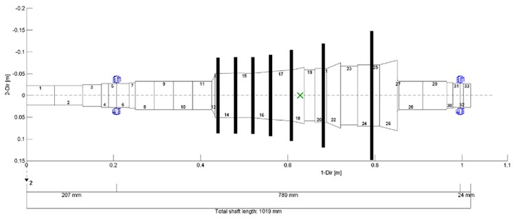
Fig. 2Diagram of the assembly consisting of microturbine and generator rotors
2. Analysis of the microturbine's dynamic properties
The creation of a reliable vibrodiagnostic system for the test stand was accompanied with a dynamic analysis of the microturbine rotor. Fig. 3 presents vibrations of the microturbine rotor. At 186 Hz, transverse vibrations of this rotor occurred. The first mode of vibration was shown. For the microturbine and generator rotors, full kinetostatic, dynamic and strength analyses were performed. However, due to the subject of the article, only selected results of dynamic analyses are presented below. During analyses of the microturbine rotor, a bearing system consisting of 2 bearing nodes was taken into account. The modal analysis of the rotating system (of the microturbine and of the generator) suggested that this system has numerous forms of natural vibration in the low frequency range. And so, these vibrations can be induced by dynamic excitations created during machine operation.
The next stage of the dynamic analysis of the ORC microturbine’s rotating system was the analysis of vibration excited by the harmonic force induced by the unbalance. The vibration amplitude of the rotor is presented in Fig. 4. The obtained results suggest that the first critical speed of the system occurred at ca. 11,000 rpm.
The disk’s vibration amplitude at this speed grew rapidly and got up to 300 μm, and in bearing no. 2 up to 150 μm. In the scope of rotational speeds, which are of the most interest to us, vibration amplitudes were extremely low which proved very good dynamic properties. Based on the obtained results it can be concluded that, in terms of vibration, the microturbine rotor was subcritical.
Fig. 3Lateral vibrations of the microturbine rotor at 186.2 Hz
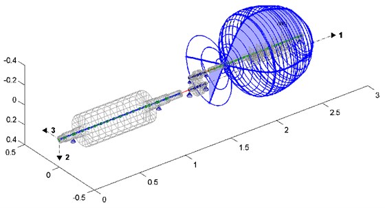
Fig. 4Vibration amplitude of the microturbine rotor vs. rotational speed
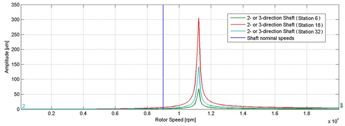
Fig. 5 presents a Campbell diagram of the microturbine rotor. The nominal speed of the rotor was signed with the blue vertical line whereas the range of speeds close to the nominal speed (from 8,500 rpm to 9,500 rpm) was shaded. According to the results presented in the above diagram, the rotating system will not go through the critical speed until the nominal speed is reaching.
Fig. 5Campbell diagram of the microturbine rotor
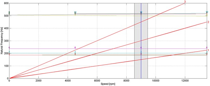
At speed range from ca. 3,500 rpm to 7,000 rpm there is a serious risk that the first, second, third and fourth form of natural vibrations of the rotor will be induced because the lines corresponding to components 2x and 3x intersect with the lines of natural vibration frequencies.
3. Diagnostic system
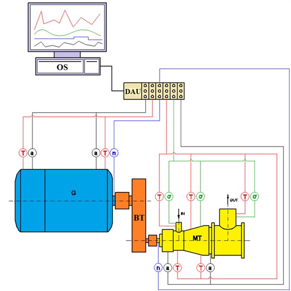
The diagnostic system has been designed by the employees of the Department of Turbine Dynamics and Diagnostics at the IMP PAN based on the results of the previously discussed dynamic analysis. It is intended to be used for diagnostics and real-time monitoring of the current state of the machine and also for collecting, archiving and visualising the measurement results. The system architecture is based on solutions that are commonly used in diagnostic systems applied to fluid-flow machines [12, 13], and the measurement points' location was chosen based on the research team's experience [14, 15]. To meet the system needs and be able to monitor the operation of the turbine set in real time, an NI CompactRIO programmable automation controller was used. The constructed measurement data acquisition system is shown in Fig. 6. Assessing the state of the operating machine is done using carefully selected high-performance meters that allow measuring the following quantities: temperature, deformations, vibrations, and rotational speed.
Fig. 6Scheme of the diagnostic system for the turbine set (MT – microturbine, BT – belt transmission, G – electric generator, DAU – data acquisition unit, OS – operator station, T – temperature, a – acceleration, n – rotational speed, σ – deformations)
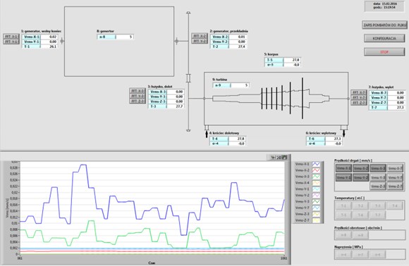
In order to enable online access to the monitored parameters, a measurement and control application has been created using the LabVIEW, which is a graphical programming environment provided by National Instruments. The application utilises an FPGA module (used to program the operation of devices at the hardware level), a parent application run in the CompactRIO controller, and an application launched at the operator station that communicates with the CompactRIO controller through the Ethernet port. All these software components are linked together in one application, created using the LabVIEW environment. The main graphical component of the application is the MONITOR window (see Fig. 7). It is where the currently measured quantities are displayed (in numerical form). It also serves for data acquisition purposes. The application allows creating plots of the measured quantities versus time. Moreover, it can display (in a pop-up window) a frequency spectrum for the selected vibration signal. When the threshold values are exceeded, the system reports warning messages and suggests shutting down the machine.
Fig. 7The MONITOR window during testing on the test rig
4. Conclusions
The article describes a new vibrodiagnostic system designed for a complex rotating system consisting of an ORC microturbine with an electric power of 100 kW, a power generator, a gear and two couplings. The first part of the article presents results of the dynamic analysis of the rotating system, which helped to select the measuring points. Calculation results proved that the rotating system is subcritical which means that the critical speed of each rotor occurs above the assumed range of working speeds. However, a detailed study suggested the risk of inducing the generator’s natural vibration during the run-up of the microturbine rotor. The probability that such phenomenon will occur depends on several factors, among others, the vibration level of the microturbine rotor during its acceleration and the ability to transmit vibration. What is more, analysis of the Campbell diagram suggested a risk of inducing forms of the rotors’ natural vibration as a result of manifestation of higher harmonic components (2X and 3X). This type of vibration may occur even at a minimal bend of the shaft or misalignment of the rotating system’s bearings. In this case, the best preventive method may be very precisely manufacture, balance and align individual rotors. Therefore, in the analyzed system there may occur coupled vibrations of various sub-assemblies.
Knowledge gained based on the conducted analyses allows to conclude that the studied system, during startup and first hours of operation, will require special attention and supervision by qualified diagnosticians. Due to the fact that several different unfavorable dynamic phenomena coincide with one another, prior to putting the system into service, one must also develop the so-called reference states of this machine allowing to assess and predict its dynamic state in the future.
The second part of the article describes a new vibrodiagnostic system that was developed at the IMP PAN in Gdańsk. The system is intended to be used for the real-time control of the technical condition of a prototypical vapour microturbine. It fulfills the function of a control and monitoring tool and can help in an early detection of a failure/malfunction that occurred or is about to occur. The vibration level of the turbine set needs to be monitored because if it is too high, that can lead to a premature wear of the bearing(s), a contact between the rotor and casing or even a serious machine breakdown. The article presents the diagnostic system equipped with a measurement and monitoring application. The final implementation of the system and its adjustment to the 100 kW microturbine will be possible after the preparation of the ORC system for power generation is complete. The diagnostic system presented herein is so versatile that it can also be used for monitoring the technical condition of other turbomachines.
References
-
Beith R. Small and Micro Combined Heat and Power (CHP) Systems. Woodhed Publishing Limited, 2011.
-
Peirs J., Reynaerts D., Verplaetsen F. A microturbine for electric power generation. Sensors and Actuators, Vol. 113, 2004, p. 86-93.
-
Kozanecki Z., Łagodziński J. Magnetic thrust bearing for the ORC high-speed microturbine. Solid State Phenomena, Vol. 198, 2013, p. 348-353.
-
Kiciński J., Żywica G. Numerical analysis of the steam microturbine rotor supported on foil bearings. Advances in Vibration Engineering, Vol. 11, Issue 2, 2012, p. 113-119.
-
Kozanecka D., Kozanecki Z., Tkacz E., Łagodziński J. Experimental research of oil-free support systems to predict the high-speed rotor bearing dynamics. International Journal of Dynamics and Control, Vol. 3, Issue 1, 2015, p. 9-16.
-
Otsu Y., Somaya K., Yoshimoto S. High-speed stability of a rigid rotor supported by aerostatic journal bearings with compound restrictors. Tribology International, Vol. 44, 2011, p. 9-17.
-
Kiciński J. The dynamics of microturbines lubricated using unconventional agents. Bulletin of the Polish Academy of Sciences, Technical Sciences, Vol. 63, Issue 2, 2015, p. 369-377.
-
Żywica G., Drewczyński M., Kiciński J., Rządkowski R. Computational modal and strength analysis of the steam microturbine with fluid-film bearings. Journal of Vibration Engineering and Technologies, Vol. 2, Issue 6, 2014, p. 543-549.
-
Żywica G., Kiciński J. The influence of selected design and operating parameters on the dynamics of the steam micro-turbine. Open Engineering, Vol. 5, Issue 1, 2015, p. 385-398.
-
Dominiczak K., Rządkowski R., Radulski W., Szczepanik R. Online prediction of temperature and stress in steam turbine components using neural networks. Journal of Engineering for Gas Turbines and Power, Vol. 138, Issue 5, 2016, https://doi.org/10.1115/1.4031626.
-
Kubitz L., Rządkowski R., Gnesin V., Kolodyazhnaya L. Direct integration method in aeroelastic analysis of compressor and turbine rotor blades. Journal of Vibration Engineering and Technologies, Vol. 4, Issue 1, 2016, p. 37-42.
-
Barszcz T. Machine Monitoring and Diagnostic Systems. ITE – PIB, Cracow, 2006, (in Polish).
-
Barszcz T., Urbanek J. Monitoring and Diagnostics of Rotor Machines. ITE – PIB, Cracow, 2008, (in Polish).
-
Żywica G., Kiciński J. The influence of selected design and operating parameters on the dynamics of the steam micro-turbine. Open Engineering, Vol. 5, 2015, p. 385-398.
-
Żywica G., Bagiński P., Breńkacz Ł. Dynamic state assessment of the water turbine with the power of 600 kW. Diagnostyka, Vol. 14, Issue 1, 2013, p. 65-70.
About this article

The research work was supported by the strategic program of the National Centre for Research and Development in Poland “Advanced Technologies for Energy Generation” within the Research Task No. 4 – “Development of Integrated Technology of Fuels and Energy from Biomass, Agricultural Waste and Other Resources”.
