Abstract
This article is devoted to the issues of assessing the operational functionalities of the vehicle supercharging system on the turbocharge. The article presents assessment of turbocharger technical state verification procedure includes supercharging parameters, damage analysis, turbine blade strength analysis for chosen vehicles, and turbocharger impeller stand tests. The most frequently occurring failures and defects of supercharging devices are presented included their reasons. The main part of the work includes the strength analysis of the impeller blades, the verification of their deviations, and the stand tests by using specialized equipment.
1. Introduction
Supercharging is a process to increase the amount of charge in the cylinder, at elevated pressure and constant temperature, resulting in an increase in density, mass charge in the cylinder.
The turbocharger turbine wheel is the most important part of device assuring the compressor wheel shaft drive.
The turbocharger turbine wheel is made from chromium-nickel-wolfram heat – treatable constructional steel, which has a chemical construction: 0,25%C, 0,4%Mn, 1,5%Cr, 4,2%Ni and 1%W [1]. The examples of turbocharger shaft with turbine and compressor rotors were introduced on Fig. 1.
Fig. 1Turbocharger shaft with turbine and compressor rotors [own source]
![Turbocharger shaft with turbine and compressor rotors [own source]](https://static-01.extrica.com/articles/18984/18984-img1.jpg)
![Turbocharger shaft with turbine and compressor rotors [own source]](https://static-01.extrica.com/articles/18984/18984-img2.jpg)
![Turbocharger shaft with turbine and compressor rotors [own source]](https://static-01.extrica.com/articles/18984/18984-img3.jpg)
The turbocharger selection for combustion engines is chosen in two steps. The first step of selection is related with the requirement of the air by the engine.
2. The study of turbocharger damage
Companies producing internal combustion engines tend to get very good indicators of the work drive unit and reduce consumption fuel while reducing emissions of toxic exhaust gases. A common solution to the above is the use of turbochargers.
During the maximum load of the turbocharged internal combustion engine, the charging equipment is exposed to extreme operating conditions. The turbocharger impeller rotates at a speed of 40,000-180,000 min-1. The high exhaust gas temperature that affects the turbine wheel oscillates within 700 °C for propulsion, while in spark ignition engines, this is around 1000 °C. These operating conditions make it clear how simple a turbocharger can be.
Table 1 shows typical and most frequent damage to the turbocharger.
Table 1Turbocharger damage [2, 3]
Type of damage | Cause of damage | Result of damage |
![Turbocharger damage [2, 3]](https://static-01.extrica.com/articles/18984/18984-img4.jpg) Broken turbine wheel blades | - “Foreign bodies” in the sucked air - high rotational speed of the rotating element -dirty air filter | - loud work - no power - blue smoke |
![Turbocharger damage [2, 3]](https://static-01.extrica.com/articles/18984/18984-img5.jpg) Pollution on the turbine wheel | - large amount of oil - irregular oil change - sudden engine shutdown, High exhaust gas temperature | -black smoke - bearing defect -cleaning of sealants - loud work |
![Turbocharger damage [2, 3]](https://static-01.extrica.com/articles/18984/18984-img6.jpg) The shaft overheat with running track damage | - the incorrect quantity of motor oil - injector damage - damage of lubrication system - sudden engine stop | - less engine power - black exhaust smoke - damaged bearings |
![Turbocharger damage [2, 3]](https://static-01.extrica.com/articles/18984/18984-img7.jpg) Cracked compression wheel | - “Foreign bodies” in the sucked air - too high rotational speed of the rotating element - used air filter - leaky intake system | - noisy work - no power - damage to the EGR system - black flue color |
3. The stress analysis procedure [4, 5]
The stress analysis procedure can be considered in the following steps:
1. Select the right material with the correct physical and mechanical parameters,
2. Marking the fixed bindings on the geometric model,
3. Define the load on the rotor blades while operating the engine,
4. Discrediting of the numerical model – setting the grid parameters,
5. Investigation simulation,
6. Final results.
Created virtual models were introduced on Fig. 2.
Stress analysis was performed for two rotational speeds of the rotor: 80,000 min-1 and 120,000 min-1. The Fig. 3 shows the stress distribution for the above speeds.
The comparison of received results during conducted investigations was introduced in Table 2.
Fig. 2Turbine wheel virtual models [3]
![Turbine wheel virtual models [3]](https://static-01.extrica.com/articles/18984/18984-img8.jpg)
Fig. 3The stress analysis on the vehicle rotor [6, 7]
![The stress analysis on the vehicle rotor [6, 7]](https://static-01.extrica.com/articles/18984/18984-img9.jpg)
Table 2Results of simulations [3]
Stress investigations | |||
Rotation speed | Vehicle type | ||
Mercedes- Benz Actros | Mercedes- Benz Sprinter | Peugeot 308 | |
80 000 min-1 | 26,36 MPa | 31,24 MPa | 110,2 MPa |
120 000 min1 | 33,53 MPa | 61,04 MPa | 175,1 MPa |
180 000 min-1 | 92,91 MPa | 122,01 MPa | 301,06 MPa |
Displacement of rotor blades | |||
Rotation speed | Vehicle type | ||
Mercedes- Benz Actros | Mercedes- Benz Sprinter | Peugeot 308 | |
120 000 min-1 | 0,03567 mm | 0,05639 mm | 0,1526 mm |
4. Stand turbocharger test
Charging devices have been subjected to testing for the correction of unbalanced turbocharger coil measurements, the turbocharger turbocharger balancing with the compression wheel, and the variable geometry adjustment system depending on the angle of the steering vanes.
The analysis was carried out on three specialized devices:
• Schematic MBSC 110 for turbocharger core correction,
• TB Comfort Scheme for balancing the turbocharger shaft with the compression wheel,
• Cimat TurboTest to the geometry variable system verification.
Verification of the variable geometry system involved placing the vehicle car turbocharger in the adapter and connecting to the oil system. Operating conditions simulation tests of the car’s charging device are possible because due to the dynamic mode. The turbocharger is lubricated and oil-cooled at the right temperature and pressure. The study was conducted for three angles of blade positioning in a variable geometry system. The maximum speed of the rotor oscillated within 85,000 min-1. The following results are presented in the Table 3.
The main aspect of the Geometry Variable System study is the airflow maintain and pressure values in the green tolerance field on the discs above. The above value is controlled by a specialized nut and a tie that is responsible for the turbine vent valve operation. This valve adjusts the angle of the vanes in the variable geometry system incline, depending on the load of the drive unit.
Table 3Test results during system variable geometry verification
Verification of flow and air pressure | ||
Rotor speed 20,000 min-1 | Rotor speed 65,000 min-1 | Rotor speed 90,000 min-1 |
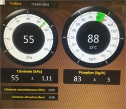 | 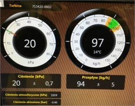 | 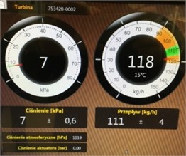 |
5. Conclusions
Turbochargers have been tested in terms of strength tests to the distribution of stresses on turbine rotor blades verification depending on the drive load and stationary tests. Analyzed turbocharger rotors, as well as the core system of variable geometry. An important assumption of the study was planned during the mapping of complex shapes, curves, impeller blades. This plays a significant role in terms of accuracy, reliability testing. The result is a numerical models turbocharger rotors for the three types of vehicles. Simulation was carried out on them, taking into account the dynamic loads of the internal combustion engine and associated mass forces.
The distribution of the stress acting on the rotor, and the verified amount of deflection of the rotor blades from the nominal position.
From regard of difficulty in the obtainment of the information relating materials used to the rotor building, we put into analysis the Inconel 713 oC alloy. The durability analysis was realized for given speeds of rotor: 80000 rpm, 120000 rpm and 180000 rpm.
The results of investigations presented in this paper do confirm that stand test based virtual tools used for assessment of the operational functionality of the vehicle supercharging system can be effectively used for testing turbochargers.
References
-
Mysłowski J. Engines Turbocharger. Communications and Merchandising Publishers, 2006, (in Polish).
-
Salk N. Metal injection moulding of Inconel 713C for turbocharger applications. Powder Injection Moulding International, Vol. 5, Issue 3, 2011, p. 17-26.
-
Wojciechowski H. Assessment of Turbochargers Parameters Influence on the Exploitation Properties for Selected Vehicle. Master Thesis, UTP Bydgoszcz, 2016, (in Polish).
-
Łukasiewicz M., Kałaczyński T., Liss M., Musiał J., Matuszewski M. Determining the complex technical objects own frequency by modal analysis methods. Bulletin of the Kiev National University Technologies and Design, Vol. 3, Issue 3, 2013, p. 38-42, (in Polish).
-
Łukasiewicz M., Kałaczyński T., Musiał J., Shalapko J. Diagnostics of buggy vehicle transmission gearbox technical state based on modal vibrations. Journal of Vibroengineering, Vol. 16, Issue 6, 2014, p. 2624-3168.
-
Kałaczyński T., Łukasiewicz M., Liss M., Kasprowicz T. The exploited machine engines technical state assessment with applicability of LMS Virtual.Lab. V Ukrainian-Polish Scientific Dialogues Khmelnitsky-Yaremche, Vol. 1, Issue 1, 2013, p. 245-254.
-
Łukasiewicz M., Kałaczyński T., Liss M., Kanigowski J. The LMS Virtual.Lab application in machines technical state analysis. Journal of Polish CIMAC, Vol. 9, Issue 3, 2014, p. 59-66.
About this article

