Abstract
The article describes the development and a subsequent application of a computational model for effective and fast simulations of the turbocharger rotordynamics in time domains. The simulation tool consists of two basic models which are described in the article. The rotor is modelled as a flexible structure based on the nonlinear beam approach suitable for an effective solution in the time domain. The computational model also incorporates radial and axial bearing models. Theoretical background of the inovative journal bearing computational models, based on the numerical solution of the Reynolds equation, is presented. The capabilities of the simulation and sample results are demonstrated on a middle size turbocharger rotor supported by fully floating ring bearings.
1. Introduction
There are several ways to reduce emissions, vibrations, noise and to increase power density of internal combustion engines (ICE). Downsizing, downspeeding, exhaust gas turbocharging or engines with a low number of cylinders are examples of modern trends for vehicle powertrains. And since the demands on combustion engines are still rising, the ICE manufacturers have to keep up. Utilization of turbocharging technology presents an effective way to meet these demands. Turbochargers are currently produced in large series and even the slightest simplification in the manufacturing process can lead to significant cost reductions.
Turbocharger rotors in principle present high impact on noise, vibration and harshness (NVH) of the powertrain and therefore the rotor dynamics is an area of interest in turbocharger development. The development of new technologies has to be supplemented by an appropriate research of the computational methods for a problem solution as they are approaches solving rotordynamics or component tribology.
In general, the noise of automotive or heavy duty truck turbochargers can be caused by airflow in the compressor wheel, rotation of the compressor and turbine wheels, rotor unbalance or oil whirling in the radial bearings. Turbochargers excite vibrations and generate the airborne and structural borne noise in environment. The pulsation noise, rotation noise, growling noise or whining noise are classical types of airborne noise occurring in turbochargers [1]. Unbalance whistle and constant tone are other types of turbocharger noise requiring a significant concern already in the development phase. Unbalance whistle is caused by the unbalanced rotor and the unbalance change of the rotor after long operating time. Its harmonics frequency of first order typically varies between 1 000 Hz and 4 500 Hz. Constant tone is induced by the oil whirling in the inner or outer radial bearing. Its frequency is between 200 and 1000 Hz. The frequency order of the inner oil whirl in the rotating floating ring bearings reduces from about 0.2-0.35 as the rotor speed increases. Unlike the previously listed noises, the unbalance whistle and constant tone can be analysed by structural dynamic models being described in next chapters.
2. Review of the state of the art
One of the greatest challenges of the turbocharging technology is its very high speed range. Modern turbochargers operate in speeds up to 300 000 min-1. Turbocharger rotor dynamics and its modelling are historically based on simple linear models, but this solution is not sufficient. A major breakthrough was introduced by Schweizer [2], who used multibody dynamics software (MBS) based tool for the prediction of turbocharger rotor dynamics. This type of a model is the most commonly used for turbocharger rotor dynamics simulation. For example, Tian [3] used this type of a tool to create a model to study the influence of the rotor unbalance and engine vibration on turbocharger rotor dynamics and published the results. The use of multibody based computational models seems to be a very effective way to solve the structural dynamics of turbocharges [4, 5].
Radial and axial bearings are the key components of every rotating machine and therefore the computational models of bearings are critical part of every computational model of turbocharger rotordynamics. The turbocharger rotor model being analyzed presumes hydrodynamic radial bearing with fully floating ring as a standard solution of turbocharger rotor and housing interactions.
In the technical literature the problems of slide bearing modelling (interaction of rigid part and a thin fluid layer) are frequently published and described in quite a detail, e.g. references [6-8], they are studied qualitatively for more than a century. The theory of lubrication is based on Reynolds equation – this nonlinear partial differential equation has also been experimentally validated.
The Reynolds Eq. (1) assumes that the oil is considered massless and incompressible with adhesion to the bearing surface, with the characteristics of Newtonian liquids with constant viscosity throughout the volume of the oil film. The oil flow is considered laminar, surfaces of the bearing are considered to be perfectly smooth, while the oil layer thickness is small in comparison to the radius of the bearing, and with flow velocity in the radial and axial direction only. Curvature of the oil film, the temperature differences and inertial forces of the fluid, which would be included in the Reynolds equation for correct description, are neglected. This basic equation can be presented in the following form:
where , are coordinates, is time, is oil film thickness, is pressure, is oil density, is oil dynamic viscosity and and are the surface velocities of the pin and the shell, respectively. The Reynolds equation has to be supplemented by the cavitation equation. Cavitation phenomenon, in general, usually occurs in the regions of diverging gaps filled by liquid under sub-ambient pressure. These very low pressures cause a transformation of liquid to liquid-gas mixture. Numerous cavitation algorithms have been proposed over time. The basic ones, like Half-Sommerfeld or Reynolds, can be used. A more sophisticated approach was introduced by Jacobsson and Floberg [9]. Elrod [10] introduced a new cavitation algorithm using only a single equation for the whole lubrication region without the need to locate cavitation boundaries. These algorithms are, in general, mass conservative and if thermal effects are to be considered more in detail, there is definitely a need to use these or similar approaches. However, if the main required result is the pressure distribution in oil film, then the numerically simple Reynolds description of cavitation can be used.
Historically there are many approaches for numerical solution of the Reynolds Eq. (1). One of the straight forward and relatively simple approaches is introduced in the work of Butenschön [6] published in 1976. Despite many simplifications this approach can still be used for fast computational models.
Reynolds Eq. (1) requires the definition of oil film thickness. The oil film thickness consists of several components, i.e. the component reflecting the assumption that the pin and the shell are absolute rigid bodies – . The second component is the elastic deformation , while the third component includes deviations of the pin or the shell from an ideal cylinder or shell due to initial deformations. The total oil film thickness reads as:
Friction losses are one of the most important results and therefore the definition of shear stress is:
Oil film temperature presents high impact on dynamic solution via a modification of oil dynamic viscosity. The influence of oil temperature on dynamic viscosity is really significant and has to be always considered. In general, there are two main mechanisms how heat is transferred thru the bearing – heat convection by oil flow and heat conduction by solid components. Head convection is presumed to be more important and in many cases also dominant mechanism. Therefore, it is necessary to incorporate the temperature behavior into a computational model, but maintain relative simplicity.
3. Aims of the computational modelling
A computational model of the turbocharger rotordynamics is solved in time domain considering positives and negatives of transient nonlinear dynamics. This approach enables to incorporate different physical problems, including various nonlinearities, but sometimes leads to long solution times.
The solution speed is always critical for turbocharger developers and thus it is defined as main condition which has to be considered in computational model development.
An efficient and robust computational model capable to solve the turbocharger rotordynamics is the main aim of this research work. The computational model being presented has to consider:
– Non-linear behavior of rotor dynamics.
– Non-linear and temperature dependent behavior of hydrodynamic bearings.
– Model robustness and solution effectiveness.
– Direct calculation of NVH results.
– Direct calculation of tribological results.
– Capabilities for assembling into large powertrain models.
4. Computational approach
4.1. Modelling of rotor shaft
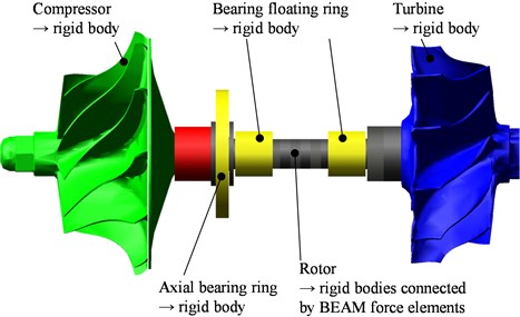
The rotor shaft is modelled by beams using the Timoshenko’s non-linear formulation including stress stiffening and spin softening effects. Stress stiffening is the stiffening (or weakening) of a structure due to its stress state. This stiffening effect normally needs to be considered for thin structures with bending stiffness very small compared to axial stiffness, such as thin beams, and shells and couples the in-plane and transverse displacements.
This effect also augments the regular nonlinear stiffness matrix produced by large-strain or large-deflection effects. The effect of stress stiffening is implemented by generating and then using an additional stiffness matrix. The additional stiffness matrix is added to the regular stiffness matrix in order to give the total stiffness. The vibration of a spinning rotor also causes relative circumferential motions, which changes the direction of the centrifugal load which, in turn, will tend to destabilize the structure. As a small deflection analysis cannot directly account for changes in geometry, the effect can be accounted for by an adjustment of the stiffness matrix (spin softening). The resultant geometrical model in multibody software environment is presented in Fig. 1.
Fig. 1Computational model of turbocharger rotor based on multibody dynamics capabilities
4.2. Modelling of radial bearing with fully floating ring
The turbocharger rotor incorporates fully floating ring radial hydrodynamic bearings to increase the damping effects of standard hydrodynamic bearings. Since journal bearing in the MBS is represented by a set of pre-calculated databases, several presumptions [8] have to be considered to be able to create these databases in advance. The scheme and general dimensions of the fully floating ring bearing is shown in Fig. 2. The bearing consists of three parts – a housing bore, a shaft and a floating ring. The floating ring separates the shaft from the housing bore, and therefore, two oil films are created – inner and outer.
Fig. 2Model arrangement of radial bearing with floating ring
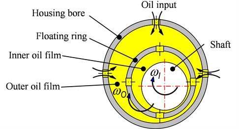
Floating ring bearing has three different eccentricities which describe the position of floating ring and shaft – overall eccentricity (between shaft and housing bore), inner eccentricity (between shaft and floating ring) and outer eccentricity (between floating ring and housing bore). Computational models have to address at least the following features:
• Reaction forces.
• Friction moments.
• Oil mass flow.
• Maximal values of oil film pressures.
• Averaged oil film temperatures.
The classical theory of solution consisting of the separation of the Reynolds equation into two parts [6, 8] cannot be used due to the presence of oil bores on the floating ring and housing bore. The innovative approach consists of the separation of Reynolds Eq. (1) into three parts:
• Reynolds Eq. considering only tangential pin movement Eq. (4).
• Reynolds eq. considering only radial pin movement Eq. (5).
• Reynolds eq. considering only oil flow due to input oil pressure Eq. (6).
The governing equations can be written as:
Reynolds Eq. (4-6) are transformed into non-dimensional forms. These forms introduce advantages for the numerical solution. The substitutions are presented as:
where is dimensionless height of the oil film, is dimensionless coordinate along bearing width, is bearing diameter (inner or outer diameter depending on which oil film is modelled), is bearing width (inner or outer width depending on which oil film is modelled), is relative eccentricity, is half of radial clearance. The symbols and are constants used to simplify the equation.
The main parameter that influences the distribution of the hydrodynamic pressure is the non-dimensional height of the oil film . The non-dimensional height of the oil film, considering eccentricity and both tilt angles, is shown [11]:
where dimensionless eccentricity depends on which oil film is modelled and and are dimensionless journal tilt angles.
Pressures corresponding to Eqs. (4-6) are transformed into dimensionless forms as:
The symbol means dimensionless pressure, is input oil pressure, is time derivative of relative eccentricity, the index in general is connected to tangential pin movement, index r to radial pin movement and index to oil flow under input oil pressure. Eq. (8, 9) are used to modify Eqs. (4-6) and the final forms read:
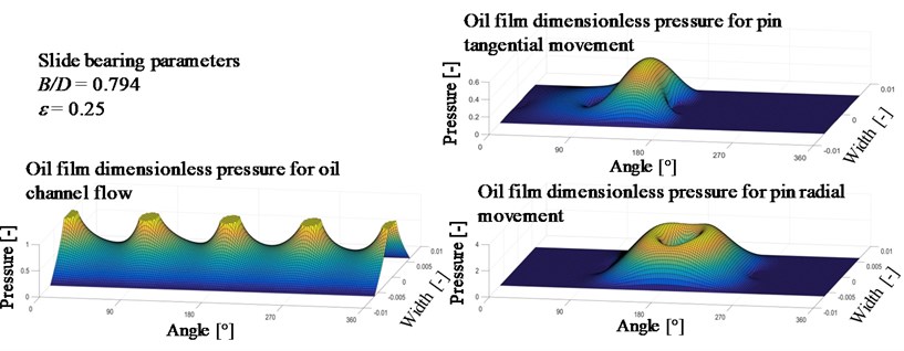
The Reynolds differential equations are discretized by finite difference method (FDM) and iteratively solved by Gauss-Seidel method employing successive over-relaxation strategy (SOR). The cavitation condition ensures that the pressure in the oil film is always higher or equal to cavitation pressure. Typical dimensionless components of pressure are presented in Fig. 3.
The radial bearing model is introduced to the MBS as a set of dimensionless result tables and equations. The resultant table carries the values of dimensionless forces and torques. This approach enables to solve the distribution of the hydrodynamic pressure in advance; and therefore, secure significantly faster solution.
Fig. 3Dimensionless pressure components used for hydrodynamic pressure calculations
To create the hydrodynamic databases, the solver needs eccentricity and diameter to width ratio; every other parameter (e.g. bearing width, diameter and clearance, oil viscosity, etc.) is then entered afterwards during the conversion of forces to real values using equations:
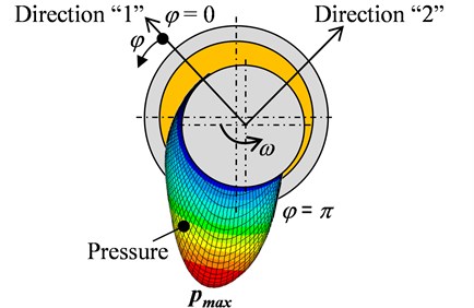
The symbols , , , , are reaction forces in oil film in directions relative to minimal oil film thickness, is effective angular velocity, is dimensionless clearance and is dimensionless reaction force database. Index 1 means direction in minimal oil film thickness, index 2 means direction perpendicular to minimal oil film, indexes and mean pressures due to tangential and radial pin movement, respectively, and index means pressure resulting from the oil flow due to input pressure. The bearing directions are presented in Fig. 4.
Fig. 4Description of bearing relative directions, “1” means direction in minimal oil film thickness, “2” means direction perpendicular to minimal oil film thickness
Dimensionless reaction force databases are dependent only on and . The values can be calculated as follows:
Maximal pressures in oil film at given time are also precalculated as:
where are dimensionless maximal pressures stored in databases for tangential and radial pin movement, respectively.
Generally, friction moment of the hydrodynamic bearing can be calculated as:
where is a bearing area, is friction moment component due to non-uniform pressure (rolling component) and is friction moment component due to sliding (sliding component). Components of Eq. (18) are transferred into dimensionless form as:
The non-dimensional friction databases (and ) are defined as:
Values of side oil mass flow for both pin movements and side oil mass flow due to input pressure can be determined as:
and dimensionless mass flow databases are prescribed as:
The dimensionless forces (, , , ) are stored in hydrodynamic databases and they are read during the solution of rotordynamics. The transition to the dimensionless form enables to solve the equation effectively and also to solve the equation for groups of bearings (depending only on ratio and ).
Averaged temperature of bearing oil film presuming only heat convection by oil flow can be calculated as:
where is averaged oil film temperature, is input oil temperature, is relative angular velocity, is friction moment, is specific heat capacity of oil and is total oil mass flow.
4.3. Implementation of innovative models
The innovative model is assembled, as well as, numerically solved in multibody system ADAMS. ADAMS is a general code and enables the integration of user-defined models directly using ADAMS commands or using user written FORTRAN or C++ subroutines. ADAMS C++ solver of version 15 is used for numerical calculation of the results.
The computational model includes all significant components necessary for rotordynamics solution. A rotor shaft, compressor and turbine wheels and hydrodynamic axial and radial floating ring bearings are the main parts of the model. The model includes also beam and general force elements as a key feature. The inputs for ADAMS model are calculated by user written program in MATLAB. The user written program calculates results of a hydrodynamic problem described by Reynolds Eq. (1) and it also writes the results (, , , ) into ADAMS input data files.
5. Result examples
5.1. Verification of computational models
In general, a verification of computational methods in the case of turbocharger rotordynamics is highly difficult. High rotational speeds, small dimensions or high temperatures are the reasons why only a few experimental approaches can be used. It is very important to mention, that there are a lot of input parameters influencing the rotordynamics and these have to be very carefully considered. Rotor unbalance, bearing clearances, temperature deformations and angular positions of unbalances are very important to correctly set-up.
Table 1Selected operating data of turbocharger rotor during revolution sweep simulation
Minimal rotor speed | 20 000 rpm |
Maximal rotor speed | 100 000 rpm |
Time of revolution sweep | 5 s |
Lubricating oil (SAE specification) | 0W-30 |
Input oil temperature | 100 °C |
Input oil pressure | 0.5 MPa |
Revolution sweep from minimal to maximal rotor speed during time period is the operating regime being simulated and measured. Table 1 presents selected operating data of turbocharger rotor during revolution sweep simulation.
The computational model is verified by a measurement of compressor nose movement in two directions. Fig. 5 presents the peak-to-peak values of displacement magnitude of compressor nose vs. rotor speed defined as:
where and are eccentricities of the compressor nose in direction and direction, respectively, considering the fact, that is a coordinate in rotor axis.
Fig. 5Peak-to-peak values of displacement magnitude of compressor nose v. rotor speed
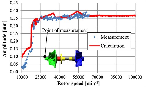
The rotor shows stable behavior only for speeds below approx. 15 000 min-1. Instabilities in outer oil film of radial bearing start above this revolution speed, the amplitudes of vibrations steeply increase and only high nonlinearity of bearing stiffness restricts the turbine or compressor wheels from touching the housing and causing serious damage. The model shows two peaks corresponding to rotor bending natural frequencies around speeds 35 000 min-1 and 55 000 min-1. These peaks are not clearly seen in the measurements. The processes in turbine and compressor chamber during rotation are the reasons why the measured vibrations are more damped.
Bearing tribology, noise and vibrations are the results being rigorously reviewed during development process of turbocharger and they will be mentioned more in detail.
5.2. Analysis of radial bearing tribology
Analysis of radial bearings starts reviewing basic results like relative eccentricity, ratio of minimal oil film thickness and combined surface roughness, maximal oil film temperature and maximal pressures in oil film.
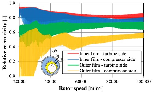
Relative eccentricity of pin in shell is a basic quantity for every bearing in development process. Fig. 6 shows relative eccentricities for inner and outer oil films for bearings on turbine and compressor sides. If the values go above roughly 0.9 then the hydrodynamic theory considering rigid shell and pin becomes not correct and in reality the bearing does not run in the best possible regime.
Fig. 6Relative eccentricities of inner and outer oil films for bearings on turbine and compressor sides
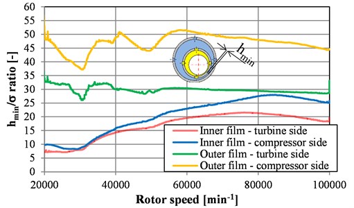
A ratio of minimal oil film thickness and combined surface roughness can be used as an indicator of increased wear of pin or shell surface. The ratio is defined as:
where is minimal oil film height, and are arithmetic mean roughness of shell and pin, respectively. The values of and combined surface roughness ratios for inner and outer oil films for bearings on turbine and compressor sides are presented in Fig. 7.
Fig. 7Ratio of minimal oil film thickness and combined surface roughness of inner and outer oil films for bearings on turbine and compressor sides
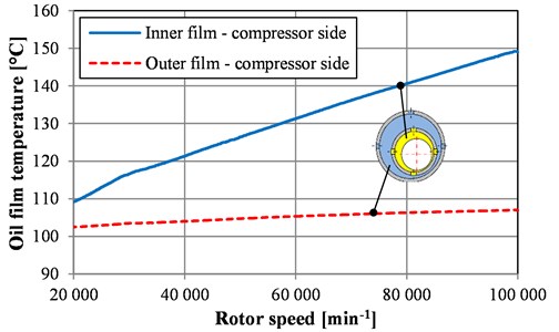
Oil film temperature presents a significant impact on rotor vibrations and tribological parameters via modification of dynamic viscosity. Maximal oil film temperature of inner and outer oil films for bearing on compressor side are shown in Fig. 8.
Fig. 8Maximal oil film temperatures of inner and outer oil films for bearing on compressor side
5.3. Analysis of rotor vibrations
The proposed computational model enables to calculate a wide range of vibrational results depending on the used modelling level. Reaction forces transferred from rotor to housing are always important results if the noise and vibrations are in concern. Fig. 9 illustrates reaction forces (amplitude) transferred from bearing outer oil film to housing vs. rotor speed.
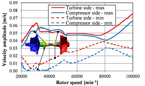
A formation of structural borne noise can be estimated from reaction forces, but component surface velocities are more suitable results in this case. Velocity amplitudes of rotor vibrations at radial bearings vs. rotor speed are presented in Fig. 10. The relative high peaks are located in low rotor speeds and they are closely connected to bearing oil film instabilities, mainly instabilities of outer oil film.
Fig. 9Reaction forces transferred from outer oil film to housing
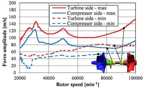
Fig. 10Velocity amplitudes of rotor vibrations at radial bearings vs. rotor speed
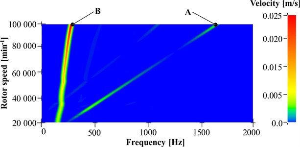
The frequency analysis using FFT algorithm of rotor velocity on turbine side are shown in Fig. 11. Line A responds to frequency of rotor rotational speed, line B corresponds to outer oil film instability (oil whirling).
Fig. 11Frequency analysis using FFT algorithm of rotor velocity on turbine side, line A responds to frequency of rotor rotational speed, line B responds outer oil film instability
6. Conclusions
Because of high rotor speeds, large unbalancing forces occurring in turbocharger systems the turbochargers cause linearly proportional noise to the frequency (unbalancing whistle) and noise connected to oil whirl (constant tone). The rotor unbalance is relatively minimalized in the case of rotor set-up and therefore the main structural borne noise is a constant tone.
Relatively high mechanical and thermal loads significantly influence radial and axial bearing tribology, but using high level computational models presented in this paper can help to avoid possible problems even in development process.
Solution speed and complexity is indivisible reality for the development of computational models. Fast solution speed as one of the main objectives of the proposed models is a big advantage. Typical solution times for one revolution sweep are approximately 4 minutes on a PC with quad-core Intel Xeon 3.4 GHz CPU and 32 GB RAM, which is really acceptable for parametric studies requested by turbocharger developers.
References
-
Nguyen-Schafer H. Aero and Vibroacoustic of Automotive Turbocharges. Springer, 2013, p. 136.
-
Tian L., Wang W. J., Peng Z. J. Dynamic behaviours of a full floating ring bearing supported turbocharger rotor with engine excitation. Journal of Sound and Vibration, Vol. 330, Issue 20, 2011, p. 4851-4874.
-
Wolff K., Steffens Ch., Aymanns R., Stohr R., Pischinger S. Turbo Charger Noise -- Development of a Methodology for the Acoustic Turbo Charger Layout. FVV Research Report 20085246, 2008.
-
Schweizer B., Rieger N. F., Black H. F., Thomas Ch. B. Dynamics and stability of turbocharger rotors. Archive of Applied Mechanics, Vol. 80, Issue 9, 2010, p. 436-471.
-
Knoll G., Seemann W., Proppe C., Koch R. Run-up of turbocharger rotors in nonlinearly modelled floating bush bearings. MTZ Worldwide, Vol. 71, Issue 4, 2010, p. 50-55.
-
Butenschön H., J. Das hydrodynamische, zylindrische Gleitlager endlicher Breite unter instationärer Belastung. Ph.D. Thesis. Universität Karlsruhe, 1976.
-
Novotný P., Maršálek O., Raffai P., Dlugoš J., Knotek J. Mixed lubrication solution with consideration of elastic deformations and real surface roughness structures. Journal of the Balkan Tribological Association, Vol. 22, 2016.
-
Novotny P. Virtual Engine – A Tool for Powertrain Development. Inaugural Dissertation, Brno University of Technology, 2009.
-
Jacobson B., Floberg L. The Finite Journal Bearing Considering Vaporization. Technical Report 190, Institute of Machine Elements, Chalmer University of Technology, Gothenburg, Sweden, 1957.
-
Elrod H. G. A cavitation algorithm. Journal of Tribology, Vol. 103, Issue 3, 1981, p. 350-354.
-
Maršálek O. Advanced Methods for the Solution of Journal Bearing Dynamics. Dissertation, Brno University of Technology, 2015.
Cited by
About this article

Outputs of this Project, named NETME CENTRE PLUS (LO1202), were created with financial support from the Ministry of Education, Youth and Sports of the Czech Republic under the Program Supporting Research, Experimental Development and Innovation: “National Sustainability Programme I”. Authors gratefully acknowledge this support.
Pavel Novotny is responsible for theory development, preparation of analytical and numerical methods, assembling the models in multibody program and providing the background in tribology and vibrations. Jozef Dlugos is responsible for numerical code implementation in multibody program and general programming support. Ales Prokop has realized measurements of rotor vibrations, evaluations of results and modifications of codes with FFT algorithms. Kamil Rehak has realized measurements of rotor vibrations, preparation of FEM models and reviewing modal results of rotors. Peter Raffai is responsible for a measurement of oil properties and preparation of bearing computational models.
