Abstract
The paper presents results of systematic computational and experimental investigations of rotordynamic induced vibrations and noise of turbochargers. The proposed solution approach is based on a combination of a virtual turbocharger and finite element method calculations of structural or acoustic domains. The virtual turbocharger is a computational model enabling simulations of rotordynamics in the time domain by multibody dynamics software. Structural vibrations and emitted noise of the turbocharger are computed by finite element method based on excitation forces calculated by the virtual turbocharger. The solution approach is proposed to rapidly calculate vibroacoustic behaviour of newly designed turbochargers in a development phase. Main results are applied on a turbocharger of diesel engine of heavy-duty vehicle.
1. Introduction
The modern trends in turbocharged direct injection gasoline engines and the rising performance requirements on modern turbocharged diesel engines produce new challenges for developers. As the internal combustion engines (ICE) are being acoustically more tuned, the acoustics of turbochargers becomes more important. Historically the acoustic optimization was based exclusively on empirical models to describe the noise behaviour of turbochargers. An efficient solution approach is necessary to develop for a solution of noise and vibration issues.
There are synchronous, sub- and super-synchronous noise sources induced in turbochargers. Necessary measures have to be applied to turbochargers in order to minimize these noises, because the induced noise of the turbocharger excites other components nearby and is transmitted to the vehicle cabin and environment. For this reason, nonlinear rotordynamic responses of the rotor have been thoroughly studied by authors for turbochargers with floating ring bearings.
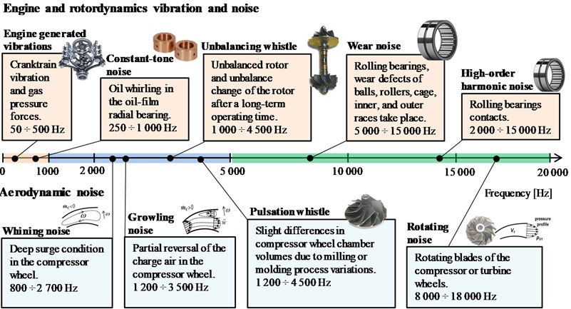
In general noise types induced in automotive turbochargers are normally classified into the following categories [1]:
• Engine induced vibrations of turbochargers. The excitation frequency is relative low for this vibration type and commonly it does not influence noise of turbochargers because its frequency lies outside of the human audible range. On the other hand, an impact on turbocharger vibrations is mostly significant.
• Unbalance whistle is caused by the unbalanced rotor and unbalance change of the rotor after a long-term operating time. Its harmonic synchronous frequency (1X).
• Constant tone (howling) is induced by the inner oil whirl due to oil whirling in the oil-film radial bearing, its frequency lies mostly in the human audible range.
• High-order harmonic noise often occurs in turbochargers using rolling bearings. This noise type can be also caused by an inappropriate design of the oil damper clearance between the bearing outer race or cartridge and bearing housing. The high-order harmonic noise has multiple harmonic frequency orders of 2, 3, 4, 5X, and above, as well as modulation sideband frequencies.
• Wear noise mostly occurs in turbochargers using rolling bearings if wear defects of balls, rollers, cage, inner, and outer races take place.
• Pulsation whistle is caused by slight differences in the compressor wheel chamber volumes due to milling or moulding process variations. It is also dependent of the number of these unequal compressor wheel chambers.
• Rotational noise is generated by the rotating blades of the compressor or turbine wheels. This noise has very high frequencies (blade passing frequency), a few kHz or higher frequency, which results from the number of blades and rotor speed.
• Growling noise is induced by the partial reversal of the charge air in the compressor wheel. Partial flow separation at the suction side near the blade outlet causes the growling noise. Growling noise propagates in the direction of the compressor outlet, and the charge-air intercoolers.
• Whining noise is induced by a deep surge condition in the compressor wheel where the charge air totally recirculates from the compressor outlet to compressor inlet. The whining noise occurs when driver suddenly releases the gas pedal, causing the required charge-air mass flow rate for the engine to besss suddenly reduced at still high turbocharger speeds. This leads to the deep surge working condition in the compressor. Whining noise propagates in the direction of the compressor inlet and the air filter system.
The induced vibration and noise types of the turbocharger separated into engine and rotordynamic vibrations and noise and aerodynamic noise are summarized in Fig. 1.
Fig. 1The induced vibration and noise types of the turbocharger
2. Simulation approach of turbocharger noise and vibrations
The aim of the research activities is to develop an effective simulation approach focusing on engine excited vibrations and rotordynamic noise, vibration and harshness (NVH). The simulation approach has to investigate influences of design parameters on turbocharger NVH by performing detailed parametric studies by means of a multidisciplinary computer aided engineering (CAE) model.
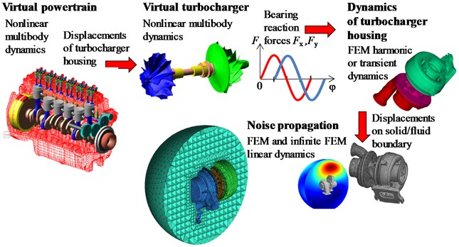
The proposed simulation approach allows to include vibration solutions from the ICE on the turbocharger. This option requires the assembling at least cranktrain computational model in a multibody system (MBS), such as a virtual cranktrain, or extend this model by a virtual gearbox or other models of subsystems. The virtual cranktrain as computational model of the cranktrain presents Drapal [3] and the virtual gearbox presents Furch [4]. Higher level of ICE models incorporating vibrations of different powertrain subsystems requires the use of a more complex computational model, e.g. a virtual engine. This approach presents, for example, Novotny [5]. The proposed simulation approach as CAE process is illustrated in Fig. 2.
Fig. 2A schema of the simulation approach for a solution of turbocharger NVH
2.1. Rotordynamic analysis
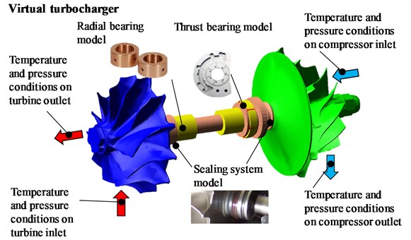
Rotordynamic analysis is realized through the computational model called a virtual turbocharger. The virtual turbocharger is a model enabling simulating reality and incorporates significant physical phenomena covering structural and fluid dynamics. The model is assembled, as well as, numerically solved in multibody system ADAMS. The virtual turbocharger includes all significant components necessary for a rotordynamic solution. A graphical representation of the virtual turbocharger is shown in Fig. 3.
Turbocharger rotor shaft, compressor and turbine wheels, hydrodynamics radial floating bearings and axial thrust bearings are the main parts of the model. The rotor shaft is modelled using flexible body based on discretised FEM (Finite Element Method) principles as demonstrates Knoll [6]. The turbocharger rotor incorporates semi-floating ring bearings to increase damping effects of common hydrodynamics bearings. The bearing consists of three parts – housing bore (sleeve), shaft and floating ring. The floating ring separates shaft from housing bore, and therefore, two oil films are created – inner and outer oil film.
Since the journal bearing is represented in the MBS by a set of pre-calculated databases, several presumptions [7] have to be considered to enable a creation of the databases in advance. For precise simulation of rotor dynamics all bearing parameters have to be known – bearing diameter, width, bore dimensions and clearances for both inner and outer oil film, oil parameters – dynamic viscosity, oil input pressure and oil temperature.
Both oil films are treated separately as a plain journal bearing. The hydrodynamic pressure and consequential forces and moments are solved numerically by a solution of Reynolds equation. The Reynolds equation is based on the modification of the Navier-Stokes equation and continuity equation transformed for cylindrical shapes of the bearing oil gap. The full form of the equation has been simplified and modified based on work of Novotny [8].
The dimensionless forces and moments calculated from hydrodynamics pressure distribution are stored in databases and they are read during a solution of rotordynamics. The transition to the dimensionless form enables to solve the equation effectively as well as to solve the equation for groups of bearing (depending only on individual bearing dimensions).
A turbocharger run-up simulation is performed from 30 000 min-1 to 120 000 min-1 for the turbocharger of a heavy-duty vehicle engine, including a remaining unbalance of the rotor. The rotor behaviour is usually analysed by conversion of the time signals into the frequency domain depicted in a Campbell diagram. This type of results evaluation has proved to be the best way to evaluate the rotor vibrations. When considering the rotor vibrations, two significant phenomena are evaluated:
• Synchronous vibrations which are caused by the unbalance of the rotor.
• Sub-synchronous vibrations with approximately constant frequency, also known as constant-tone.
Synchronous vibrations are caused by unbalance forces proportional to the unbalance and rotor speed squared. This is a dipole force acting on the turbocharger and inducing the unbalance whistle. The unbalance whistle is one of the disturbing airborne noise types of turbochargers. To reduce the unbalance whistle, the turbocharger rotor must be high-speed balanced at two balancing planes.
Fig. 3A schema of virtual turbocharger as multibody model
The root cause mechanism of the constant-tone noise is based on oil whirl phenomena [9]. Vibrations caused by oil whirl are in many cases dominant and can be considered as the main source of rotordynamic vibrations. In the case of the influence of the oil whirl on the radiated noise, the oil whirl in the inner oil layer is more significant. The outer oil layer mostly generates noise at low frequencies, that are outside of frequency bands sensitive for human.
2.2. Structural vibration analysis
A first step in a solution of structural vibrations of the turbocharger housing is modal analysis, which determines the natural frequencies and mode shapes of the structure. The natural frequencies for the housing model are being calculated up to 3 kHz. Evaluating the modal results allows to find potential resonances and enables to make the relevant design changes if resonances are found in a forced-response solution.
The next step in the proposed approach is the FEM dynamic simulation with the commercial software ANSYS. The bearing reaction forces extracted from rotordynamic results of the virtual turbocharger are loaded on the housing structure and a forced-response calculation is performed. Results of dynamic calculation includes housing deformations. As an additional result, the structural response on structure-fluid boundary surface is exported for final step of the approach, that is noise propagation analysis.
2.3. Noise propagation analysis
The noise computational simulation of turbochargers is complex issue incorporating many interdisciplinary simulations. The FEM and boundary element method (BEM) for noise propagation, finite volume method (FVM) for aeroacoustics noise generation or computational nonlinear rotordynamics is combined to simulate rotordynamic and aeroacoustics noise [1].
In the case of rotordynamics noise, the FEM is used to calculate acoustic properties of an acoustic domain. FEM directly solves equations in a three-dimensional acoustic domain surrounding the radiating surface of the turbocharger as shown in Fig. 4.
Fig. 4FE model for a calculation of noise radiation from turbocharger surface
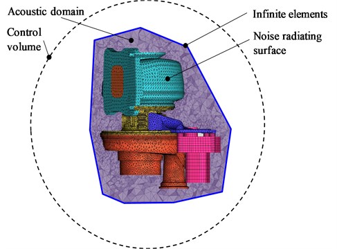
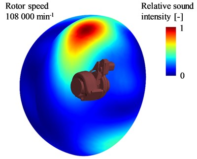
Distribution of acoustic quantities in the acoustic domain and on the control surface (located at a defined distance from the center) or integral quantities describing the sound source or the defined point in the acoustic field are solution results of the acoustic problem. Fig. 5 presents a distribution of normalised values of sound intensity, corresponding to sound directivity, on control surface as an example of acoustic calculation results.
Fig. 5A schematic diagram of a vibration separator
3. Conclusions
A fundamental understanding of turbocharger noise phenomena is obtained by the proposed approach and is also supported by experimental testing of turbocharger prototypes. This interdisciplinary concept is developed in order to represent the complex excitations and transfer paths sufficiently in detail. This concept is based on a combination of the simulations of rotor dynamics by virtual turbocharger in MBS, simulations of structural vibrations by FEM and simulations of noise propagation by FEM. The quality of the calculation model is verified with measurements obtained from the complete engine of a heavy-duty vehicle. Finally, the presented simulation approach enables an acoustically refined design of the turbocharger in the early development process.
References
-
Nguyen Schäfer H. Aero and Vibroacoustics of Automotive Turbochargers. First Edition, Springer, Berlin, Germany, 2013.
-
Pischinger S., Stoffels H., Steffens C., et al. Acoustics development for exhaust gas turbochargers. MTZ Worldwide, Vol. 69, Issue 3, 2008, p. 42-49.
-
Drápal L., Novotný P. Torsional vibration analysis of crank train with low friction losses. Journal of Vibroengineering, Vol. 19, Issue 8, 2017, p. 5691-5702.
-
Furch J., Nguyen T. Simulation of failure in gearbox using MSC.ADAMS. Acta Universitatis Agriculturae et Silviculturae Mendelianae Brunensis, Vol. 65, Issue 2, 2017, p. 419-428.
-
Novotný P., Prokop A., Zubík M., Řehák K. Investigating the influence of computational model complexity on noise and vibration modeling of powertrain. Journal of Vibroengineering, Vol. 18, Issue 1, 2016, p. 378-393.
-
Knoll G., Seemann W., Proppe C., Koch R. Run-up of turbocharger rotors in nonlinearly modelled floating bush bearings. MTZ Worldwide, Vol. 71, Issue 4, 2010, p. 50-55.
-
Novotný P., Dlugoš J., Prokop A., Raffai P. Effective computational model for a solution of turbocharger rotor dynamics. Journal of Vibroengineering, Vol. 19, Issue 2, 2017, p. 724-736.
-
Novotný P., Dlugoš J. Innovative model of radial fluid bearing for simulations of turbocharger rotordynamics. Advances in Intelligent Systems and Computing. 2018.
-
Hori Y. Hydrodynamic Lubrication. Springer Verlag, Tokyo, 2006.
About this article

The research leading to these results has received funding from the Ministry of Education, Youth and Sports under the National Sustainability Programme I (Project LO1202).
