Abstract
This paper deals with an analysis of the transmission error. For this purpose, the measuring loop was assembled from two gear boxes. Subsequently, angles, torque and shaft speed were set or measured. For the evaluation a calculation method was used, and the impact of the different transmitted torque was evaluated. The measuring loop enables to test at different operation conditions of torque and shaft rotation direction. In this paper, the static transmission error analysis for braking mode at 50 rpm shaft speed and torque range from 600 to 2400 Nm is described.
1. Introduction
The development of a gearbox for cars, trains and machines is increasingly sophisticated. Vibrations can be arisen in contact with each tooth. This is related to the quality and complexity of the developed gear and its production.
Therefore, this paper deals with the evaluation of a transmission error. It can serve as a benchmark for comparing the quality of the whole gearbox. This reveals the accuracy of the housing and shafts design, inaccuracies in production, failure or wear of tooth contacts and it can significantly affect the vibration of the whole equipment. In general, the development, vibration, noise and analysis of the powertrain described in this paper are based on [1, 2] and the measured signal processing is described in [3-5].
In the individual chapters, the measurement and data processing for transmission error are described. The measuring loop was assembled from two identical gearboxes that were connected to a closed loop. During the test, the torque was applied to the gear and the rotational speed was set as constant. The input and output shaft angle of the analysed gearbox was monitored. The paper also describes the evaluation of the transmission error and its dependence on the torque is monitored. The aim was to verify that the transmission error is smallest for the designed torque and find the maximum value of transmission error for the developed gearbox. That will affect not only vibrations but also noise.
2. Measuring loop
A measuring loop was assembled to evaluate the transmission error. This is shown in Fig. 1. The loop includes two gearboxes. Their input and output shafts are connected. The analysed gearbox is on the left and the second gearbox is used for creating a closed loop for the reason of enabling wide spectrum of torque. It is shown on Fig. 1. The input shaft of second gearbox is driven by an electric motor which determines the rotation direction of the measuring loop. During testing, the gearbox input shaft speed was 50 rpm. Possible directions of rotation are shown in Fig. 1. The plus sign indicates the positive direction of rotation speed and the negative sign indicates the opposite direction. To produce a torque, a piston rod moves up and down with the additional gearbox in the loop. This allows simulating the same transmission load by torque as in the real operation. The direction of torque is also shown in Fig. 1. Positive direction of torque occurs when the force of the piston rod is applied so that the additional gearbox is rotated about the axis of the input shaft upwards. It is described in Fig. 1 as “MOVE UP”. Negative torque value in a closed measuring loop occurs when the piston force is applied in the opposite direction and the additional gear is rotated downwards. It is described in Fig. 2 as “MOVE DOWN”.
Fig. 1Scheme of measuring loop setting
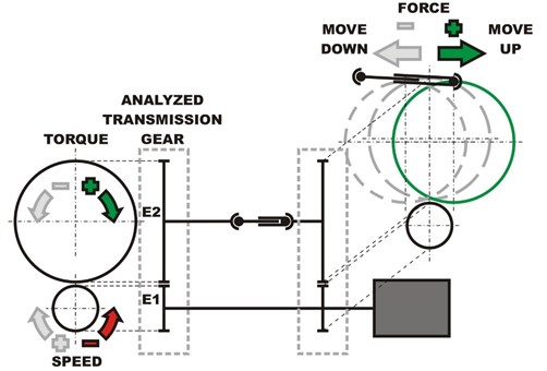
In the measuring loop the misalignment of output shaft is changing with applied torque, for that reason the cardan shaft is used. It is used to allow the gearbox to move up or down in the sufficient extent that covers the load torque. Then the braking or traction status can be set by speed and torque in both directions of rotation speed. This paper deals with analysis of the transmission error with the negative speed and positive torque. It means that braking status was induced during testing. The measuring loop was equipped with ERN 460 encoders and their locations were on the input and output shaft of the analysed transmission gear. This is shown in Fig. 1 marked E1 and E2. The encoder has two outputs that have offset signals and each output signal allows generating 3600 pulse per revolution. The measurement process was performed by setting the required torque and input shaft speed. These values were controlled by the control system. The data from the encoder were logged using a data logger for four torque setting variants of 600, 1200, 1800 and 2400 Nm. From this data, the transmission error was subsequently evaluated
3. Transmission error
The evaluation of the transmission error is based on the literature [3, 4]. The transmission error determines the smoothness of a gearbox running. Assuming infinite stiffness teeth, ideally produced tooth shape and its design, the value of transmission error would be zero. In the real condition, shafts are deformed as reaction on loading, each tooth is presented by its real stiffness and is not perfectly made. Therefore, vibration occurs during teeth contact. Therefore, a transmission error can be evaluated by Eq. (1):
where is the rotation angle of the gear pinion, – the rotation angle of the gear, – the number of teeth of the pinion, the number of teeth of the driven gear, and is the radius of the gear pith circle. Using this equation, the measured signals of the input and output shafts rotation angle were processed.
4. Evaluation of the measurement
A script in Matlab software was built to evaluate the transmission error. This code processes measured data from encoders. The processing input signal includes a timeline and data with a digital signal including the encoder location. This was recalculated to the angle of the input and output shaft rotation. To evaluate the transmission error in the same position, it was necessary to resample the output shaft data according to the input shaft position. Then the transmission error was evaluated.
Fig. 2Transmission error for 21 teeth of the gear at a torque of 600 Nm
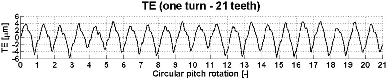
Fig. 3Transmission error for 21 teeth of the gear at a torque of 1200 Nm
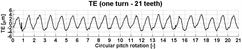
Fig. 4Transmission error for 21 teeth of the gear at a torque of 1800 Nm
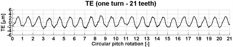
Fig. 5Transmission error for 21 teeth of the gear at a torque of 2400 Nm
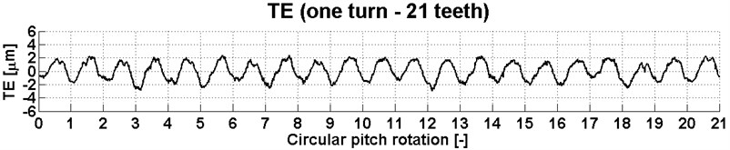
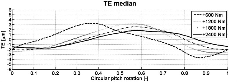
For one input shaft rotation, the transmission errors are shown in Figs. 2-5 at a torque of 600, 1200, 1800 and 2400 Nm. The graph represents contacts of 21 pinion teeth to 21 driven gear teeth, which has 120 teeth in total. In these graphs, the effect of the produce quality of the teeth or their wear can be observed. It was not the goal of this article. As mentioned, the evaluation is performed for four different value of torque. The torque influence on transmission error shown in Fig. 6. In the graph, the median transmission error is shown, and it is based on the total combination of teeth contact. From the results, it can be seen that the transmission error is decreasing during the rising torque. The goal was to verify this trend of transmission error and it was compared to the design of the tested gearbox. In this case, the developed gearbox was designed with focus on the transmission error to be the smallest at the nominal torque of 2700 Nm. This was confirmed in part because the gearbox can be loaded with a maximum torque of 2400 Nm when braking. Therefore, the next step of development will continue with the traction measurement. It will be allow the load of the gearbox with a torque up to 4620 Nm. Similar trend is expected for torque in traction mode from 0 to 2400 Nm.
Fig. 6Mean of the transmission error for all combination of contact teeth and for different torque
5. Conclusions
During each development of the gearbox, the aim is to reduced vibrations and related noise. Therefore, the individual manufacturers or institute develop methods and systems for vibration and noise analysis and their reduction.
This article dealt with the analysis of the transmission error at the gearbox for heavy application. This transmission error was used as a benchmark for prediction of vibrations. In the first step, a closed loop was assembled and tested. It consists of two identical gearboxes and supplemented with actuators, sensors and an electric motor. Subsequently, measurements were made for four setting of the transmission torque by the gearbox. The aim was confirmation of the decreasing trend of the transmission error with rising torque up to designed nominal moment. From the graph in Fig. 6, it can be concluded that this trend was achieved by the design of the gears. Further the measurement at another combination rotation speed and torque is necessary to confirm this conclusion.
References
-
Kučera P., Píštěk V. Virtual prototype of a heavy duty off-road truck driveline in Simulink software. Proceeding of International Conference Transport Means, 2014.
-
Řehak K., Kopeckova B., Prokop A. Gear drive system simulation with different model of input speed. Acoustics and Vibration of Mechanical Structures, 2017, p. 331-339.
-
Tuma J. Vehicle Gearbox Noise and Vibration. Wiley, Chichester, 2014.
-
Lei Y. G., Lin J., Zuo M. J., He Z. J. Condition monitoring and fault diagnosis of planetary gearboxes: a review. Measurement, Vol. 48, 2014, p. 292-305.
-
Artoni A., Kolivand M., Kahraman A. An ease-off based optimization of the loaded transmission error of hypoid gears. Journal of Mechanical Design, Vol. 132, Issue 1, 2010, p. 11010.
Cited by
About this article

This work is an output of the internal BUT research project Reg. No. FSI-S-17-4104.
