Abstract
The Combined Cycle Power Plants (CCPP) are widely known as the most efficient power plants. The concept of CCPP represented in Brayton and Rankin cycles combined to achieve the highest efficiency in power generation. During the fact finding, while performing the major outage, at 77,521 running hours some of the turbine blades at 1st stage found suffering from severe damages and sulfuric acid thick layer accumulated in the cooling airfoils. The blades were new, also known as the most essential and costly component installed after Hot Gas Path Inspection (HGPI) at 42,000 running hours. The main objective of this work is to study the surrounding parameters that directly affect the lifetime of the turbine blades. Furthermore, XRD analysis for new and used turbine blades are studied as well as the EDS analysis for the coating layers which are used to enhance the surface life of gas turbine blades. Corrective maintenance, on the other hand, has been undertaken to overcome the performance deterioration caused by wear, which is the result of any machine or plant’s operation. A gas turbine cannot be run reliably unless wear reserves are checked and, if necessary, restored during inspections and maintenance operations. These are performed to determine the machine's condition and the necessary condition-based repairs. The principal types of gas turbine inspection have been investigated and presented, including minor inspection, hot gas inspection, extended-scope hot gas path examination, and major inspection. Lifetime extension (LTE) measures are derived from these inspection types and go beyond the scope of a major inspection. Nondestructive testing is performed on the gas turbine’s key components. Furthermore, due to the high degree of contamination in the fuel, the turbine section must be cleaned at regular intervals. As a result of the examinations, replacement, and refurbishment intervals for important components, as well as outage time, could be recommended.
1. Introduction
1.1. Gas turbine
The gas main components, as shown below, depends on (1) compressing the inlet air to (2) burning fuel in the combustors to produce flue gases that (3) drives the turbine blades, exposing them to a very high temperature and pressure that jeopardize the hot part components such as nozzles, burners, and blades. (4) The whole mentioned process to drive the generator shaft at 3600 rpm to produce the electrical power. The healthiness of the combustion components plays a major role in reliable operation.
In this study gas turbines depend on many components and factors to operate the machine, as shown in Fig. 1. (1) Starting from quality and amount of the air going through the filters house and then to the seventeen stages of compressor that compressing and raising the air temperature to be a major player in the (2) combustion process. Moreover, (3) the purified crude oil at temperature 60 °C along with automatizing air that gives a full and complete combustion, in the silo type tow combustion chambers. Finally, (4) high temperature flue gases, 530 °C travelling through four stages of Turbine Blades and vanes.
Fig. 1Gas turbine main components
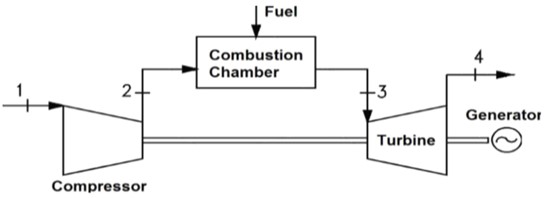
Fig. 2Image of gas turbine and its main component components
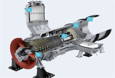
The gas turbine component (Fig. 2) identified as (a) Turbine Rotary Row (TRR): 1, 2, 3 and 4. (b) Turbine Vanes identified as Turbine Stationary Row (TSR): 1, 2, 3 and 4. All of them have tow lifetime cycles. Each cycle can be determined by: (1) fuel factor, (2) number of starts and (3) operating hours. TRR1, 2 and 3, also TSR1 and 2 goes for repair after going through many tests such as non-destructive tests: penetrate test to determine the cracks if found and ultrasound test for cracks depth and growth. These cracks should be removed and then re-built if the cracks are at the airfoil tip or at the head of the blade. If the crack is found at the lower edge of the blade, then it should be taken out by removing the cracked metal to avoid the crack growth which will cause corncob during the repair. After the second lifetime cycle, they usually scraped. Some power plants owners prefer to repair TRR and apply distractive tests to reuse them. During the whole process of cracks, scoring marks and loss of body mass can be observed. That defiantly will determine the way and category of repair.
1.2. Problem identification
During the fact-finding process, at 77,521 running hours, some of the turbine blades at the first stage discovered damage, missing elements from the blades body, and a thick layer of sulfuric acid accumulated in the cooling airfoils of the blades. The blades were brand new, having been installed following hot gas path inspection; HGPI at 42,000 running hours. This discovery explains the informality of the vibration, which was plainly visible in the trends during pre-outage data collecting.
1.3. Work objectives
The purpose of this work is to investigate the effect of surrounding features of the first stage blades in a gas turbine on the performance of the gas turbine, which is a main and vital component of any power plant station. Failure study of contaminated turbine blades employing characterization techniques such as XRD and EDS, as well as typical types of inspections such as minor inspection, hot gas inspection, extended-scope hot gas path, and lifetime extension, has been reported. Finally, the analysis of the refurbishment of the first gas turbine blades is dedicated, and as a consequence, replacement and refurbishment intervals for critical components, as well as outage time, may be advised.
2. Literature review
In order to increase the volume of compressed air, C. Celis and the other authors of the research [1] on Power Augmentation Technologies (PAT) for gas turbines cooled the temperature of the incoming air molecules. Put another way, the gas turbine’s production and performance will be increased by raising the mass flow rate and adding steam to the combustors.
Fuels’ effects on GT output efficiency and performance [2] are influenced by the mass flow through the turbine. On warmer days, the GT power output drops when the air is less dense. Power generation improves when mass flow is increased by air cooling. The gas turbine intake air is sprayed with atomized water by the fogging system. High-pressure water is pumped via nozzle holes placed over the gas turbine input ducting to generate fog. Writers: Mehaboob Basha, S. M. Shaahid, and Luai Al-Hadhrami from King Fahad University of Petroleum & Minerals in Saudi Arabia's Center for Engineering Research.
A large percentage of all failure events in gas turbine engine power plants are caused by blade damage. Preventative maintenance techniques with predetermined intervals are frequently used in current operation and maintenance (O&M) processes, which leads to high repair and replacement costs as well as large revenue losses. The decision maker has access to a multitude of data on the structural health of the blades thanks to the development and improvement of condition-monitoring technologies in recent times and the growing number of operational turbines equipped with online monitoring systems. Consequently, predictive maintenance is made possible. It is able to predict how long the blades will last, which helps O&M make decisions that try to prevent major failures. This was selected as a stand-in model and method for estimating a turbine blade's remaining life [5]. Throughout the course of the blades’ lifespan, maintenance planning may be optimized by utilizing this model in conjunction with a predictive maintenance decision framework. The aerodynamic force, centrifugal force, and maximum stress on the TRT rotor structure in rated working conditions and positions of occurrence were investigated by Lin, C.-S. et al. using the Finite Element Method (FEM). Using Campbell and SAFE diagrams, they also spoke on the dynamic characteristics of bladed disks during TRT operation [6]. The mode shapes and natural frequencies from the FEA-based modal analysis of the TRT rotor will be gathered and compared with those from the real-world constructs using Experimented Modal Analysis in order to confirm the efficacy of the finite element models (EMA). Here, we create the Modal Assurance Criterion (MAC), which verifies that the mode shapes of the finite element analysis and the real structure coincide, thereby ensuring the reliability of the finite element model. One technique to ascertain the stress distribution on the structure during rotation is to use centrifugal force analysis. The rotating blade of the TRT rotor is pushed by the blast furnace top pressure, which also generates periodic and centrifugal aerodynamic forces as the rotor rotates. When both forces apply simultaneously, the stress distribution on the structure is investigated using aerodynamic analysis.
The modal parameters obtained from the EMA are used to forecast the strength and longevity of the blades, and Campbell and SAFE diagrams are utilized to assess whether the bladed disks would resonance with the external force under the operating circumstances. The analysis's conclusions indicate that fatigue failure on the dovetail slot may happen at the maximum load when the TRT rotor is operating.
In order to efficiently carry out the probabilistic fatigue/creep coupling optimization of a turbine bladed disk, the fuzzy multi-extremum response surface method (FMERSM), which incorporates the concepts of the extremum response surface method, hierarchical strategy, and fuzzy theory, was developed [7]. Chun-Yi Zhang and colleagues examined FMERSM modeling approaches and the assessment of fatigue and creep damage in turbine bladed disks. They also presented a process for the fuzzy probabilistic FMERSM-based fatigue and creep optimization of a multi-component structure [7]. The optimization of turbine bladed disks through probabilistic fatigue/creep coupling was conducted using rotor speed, temperature, and density as optimization parameters, and reliability and GH4133B fatigue/creep damages as constraint functions. The optimization objectives included fatigue damage, creep stress, and creep damage. The findings show that gas temperature T and rotor speed! are the most important variables to control in bladed disk optimization. These parameters decrease by 85 K and 113 rad/s, respectively, following optimization, suggesting that bladed disk life will be extended, and failure damages will be decreased. According to the simulation findings, this approach performs better in terms of computational economy and modeling accuracy than the Monte Carlo technique (MCM).
On the other hand, deterioration, and failure mechanisms in the gas-path components of twin-shaft industrial gas turbines (IGTs) were investigated using a model-based approach [8]. The investigation made use of measurements from twin-shaft IGTs in the field that show a decrease in engine performance as a result of hot-end blade turbine damage, compressor fouling conditions, and variable stator guide vane (VSGV) mechanism failure. The measurements were contrasted with data that was anticipated using a Simulink thermodynamic model, which forecasts physical properties (temperature and pressure) for each of the IGT's several stations. Engine health parameters that are not accessible in engine field data, such as component efficiencies and flow capacities, are predicted by the model. The findings demonstrate that it is feasible to reproduce the change in physical characteristics across the IGT during component deterioration and failure by adjusting component efficiencies and flow capacities during IGT simulation. The model's ability to forecast observed field data related to failure in the gas-path components of twin-shaft IGTs is further demonstrated by the findings. The creation of health-index prognostic algorithms for operational engine performance prediction can benefit from the predicted health features in the gas-path components during deterioration or failure.
Fatigue failure is the most frequent kind of failure in gas turbine engine blades, and there is a critical need for an online monitoring system to identify fatigue fractures in blades. Consequently, it was suggested to employ acoustic emission (AE) monitoring for the online determination of blade status [9]. TC11 titanium alloy plates and AE monitoring of gas turbine engine blades were used in experiments on fatigue crack propagation. Before recommending a method for utilizing the AE characteristics to ascertain the crack propagation stage, the relationship between the cumulative AE hits and the fatigue crack length was established. Based on the AE energy, a method was created to forecast the degree of fracture propagation and residual fatigue life. The findings open up a new possibility for gas turbine engine blade crack monitoring in real time.
A 6.5 MW gas turbine’s first stage turbine blade failure was examined by Kolagar et al. [10]. The superalloy used to construct the blade is nickel-based, and after 6500 hours of use, the airfoils broke. To identify probable failure causes, fractography, optical and scanning electron microscopes (SEM), energy dispersive X-ray (EDX), and microstructural characterization were all used. Along with carbide breakdown, the precipitated phases’ shapes (carbides and ′ (Ni3Al)′) changed in the airfoil, for instance, ′ resolved and re-deposited. Additionally, the leading edge of the fracture surface exhibits local melting and re-solidification. The study's research and testing findings indicate that overheating is the main reason why blades break.
The reliability and safety of device components, machinery, and intricate industrial systems depend heavily on the non-destructive testing of construction parts, which is where X-ray computed tomography is becoming more and more important. The computed tomography (CT) technique used to examine the mechanical state of aviation engine turbine blades was reported by Józef Bachnio et al. [11]. It was looked at how the experimental setup affected how accurate the outcomes were. The right gas turbine blade test data were provided, and the appropriate experiment settings were selected. There have been failures, manufacturing defects, and material variances found in blades alloyed with nickel and cobalt. Selective cross-sections were used to determine the wall thickness with an accuracy of 0.01 mm, and specific cooling channel manufacturing defects were identified. It has been demonstrated that a thorough non-destructive examination of the technical state of machine parts is possible when the CT technology is used. The results of the tests showed that X-ray computed tomography might be applied to the manufacturing and maintenance of machinery.
For military or commercial fixed-wing and rotary-wing aircraft, wearable or abradable coatings in the engine's high-temperature zone are advised to increase efficiency and high-density power. The goal of developing these coated materials is to increase their resistance to wear and erosion while lowering the frequency of blade failures. It is advised to use abrasive sealants or coatings to accomplish this. The gap between the rotor and the shroud is minimized via an abradable seal at the tip of the blade. Abrasion-resistant coatings are often composed of a metal matrix, oxide particles, and void space, and are sprayed utilizing thermal spray technology. Abrasion-resistant coatings are often composed of a metal matrix, oxide particles, and void space, and are sprayed utilizing thermal spray technology. The effectiveness of a seal is dependent on its ability to maintain the right combination of characteristics during manufacturing, such as hardness and erosion resistance. A microstructure-based modeling approach was developed by Anitha Kumari Azmeera et al. [12] to help formulate abradable coating compositions by simulating the coating wear process. In order to generate an abradable coating model and carry out wear analysis using a simulated rub rig test, a variety of tools, including as Fusion360, Hyper Mesh, and LS-Dyna, were used for microstructure modeling, meshing, and wear analysis. Using simulated finite analysis models of actual micrographic images of abradable coatings, the relationship between the percentage composition and morphological variations of metal, oxide, and voids to output parameters like hardness, readability, and other mechanical characteristics was investigated.
Increasing the endurance of thermal barrier coatings (TBCs) aims to prolong the life of gas turbine engine components, such as blades and vanes. Satyapal Mahade et al. used the suspension plasma spray (SPS) method to study three double-layered gadolinium zirconate (GZ)-on-yttria stabilized zirconia (YSZ) TBC variations with varying individual layer thicknesses but the same overall thickness. The goal was to find out how the YSZ layer thickness influenced the GZ/YSZ double-layered TBCs' ability to endure different thermal cycle test circumstances, such as a burner rig test (BRT) at a surface temperature of 1400 °C and thermal cyclic fatigue (TCF) at 1100 °C. SEM was used to describe the microstructures, and image analysis was used to determine the porosity content (Scanning Electron Microscopy). According to our findings, double-layered TBCs’ durability declined with YSZ thickness in both TCF and BRT test scenarios [13]. SEM was used to examine the microstructural development and failure processes on the TBCs during TCF and BRT test settings. In the TGO (thermally produced oxide) during the TCF test and in the ceramic GZ top coat next to the GZ/YSZ contact during the BRT, the three double-layered TBC variations failed. It was discovered that the failure mechanisms varied with the test conditions. Porosity analysis of the TBCs that were as-sprayed and those that failed the TCF test also showed variations in the sintering behavior of GZ and YSZ. The results of this investigation shed new insight on the reasons why SPS-processed double-layered TBCs fail in different thermal cycling test scenarios.
Gas turbine blades coated with protective and thermal barrier coatings (TBC) corrode over time as a result of particle impacts, oxidation, and aluminum depletion. One non-destructive coating testing method (NDT) that may be utilized often in service is visual inspection, despite the fact that it can only identify surface issues and offers limited quantitative information. Andrzej Szczepankowski et al. attempted in-service monitoring of turbine blades with multilayer coatings deposited by atmospheric plasma spraying [14]. They were validated in a test cell with five other innovations in a series of turbofan engine accelerated mission tests that used to be in the military. The purpose of the fifty-hour rainbow test was to assess coating durability. In order to evaluate the blades' condition in between engine runs, borescope inspections were carried out. Ultimately, the blades underwent metallographic analysis and computed tomography (CT) scans after being disassembled. Thirty-one freshly coated blades (66 percent) passed the tests with results similar to those of the reference blades. However, serious failures including increasing roughness, gradual loss of topcoat, spallation, and minor damage from foreign objects occurred in 16 blades. Most of the time, the outcomes of the visual evaluation agreed with those of the ensuing laboratory tests.
Although internal stress at the interface in TBCs is one of the main causes of thermal barrier breakdown under thermal cycling, TBCs are widely employed to safeguard gas turbine blades. While a non-destructive inspection technique based on Eu3+ photoluminescence piezo-spectroscopy has shown useful in examining residual stress in TBCs, systematic and quantitative data processing assessment is still required, particularly for peak position identification. To assess TBC internal stress, Yanheng Zhang et al. [15] looked into data processing techniques for Eu3+ photoluminescence spectroscopic data. A sample of europium-doped yttria-stabilized zirconia (YSZ:Eu3+) was subjected to step-by-step uniaxial loading to acquire Eu3+ luminescence spectra, and in both physical and numerical experiments, the simulated spectra were numerically generated from the observed spectra. The results of many spectral data processing techniques were then compared to determine peak shifts (Gaussian, Lorentzian, pseudo-Voigt fitting, and the barycenter approach). It is found that the Gaussian function provides sufficient sensitivity, stability, and confidence for quantitative stress analysis, making it a better option for utilizing Eu3+ photoluminescence piezo spectroscopy in TBCs than the more often used Lorentzian function.
Research has been done on the impact of high thermomechanical fatigue on gas turbine lifetime in steady-state operation [16]. To get a better understanding of the connection between operating conditions and gas turbine deterioration, the growth of surface roughness between the thermal barrier coating and the bond coating was examined. Three criteria that were found to be associated with coating failure were isothermal operation, low-cycle fatigue, and severe thermomechanical fatigue. These were investigated through the use of both real service-exposed blades from a power plant and laboratory research. The findings demonstrated that isothermal heat exposure does not cause coating fatigue failure, although it does cause creep during steady-state operation. The increase of the roughness between the thermal barrier coating and bond coating of the gas turbine cannot be explained by low-cycle fatigue during a transient operation. At high operating temperatures, the temperature of hot gas pass components might fluctuate up to 140 °C, therefore severe thermomechanical fatigue during steady-state operation was a major factor in coating failure. Consequently, the prior technique only took into account creep during a steady-state operation and low-cycle fatigue during a transient operation; thus, high thermomechanical fatigue must be taken into consideration in order to appropriately anticipate the remaining usable lifetime of a gas turbine.
A flue gas turbine is the primary energy recovery device in a heavy oil catalytic cracking facility. Degradation and fracturing of the blades are the most frequent causes of gas turbine failure. Consequently, using simulation software (ANSYS), the characteristics of the flow field and rotor stress in the gas turbine were examined and simulated [17]. The study examined the impact of fume volume on various aspects such as temperature, velocity, catalyst particle movement, rotor stress, and the main position of blade erosion. Additionally, the influence law of flue gas flow on temperature gradient, pressure gradient, velocity distribution, and other factors was also examined. The maximum stress location and stress distribution of the impeller were also computed. It was found that the pressure gradient's shifting trends under various fume volumes in the gas turbine's calculation domain were comparable. Along the flow path of the hot fume, the pressure on the working face of the rotor blade gradually decreased. The front edge of the rotor blade's sharp corner with the longest radius was the site of the greatest pressure. Changes in the fume flow rate had no effect on the machine's overall temperature field. The rotor blade’s leading edge and tail were especially vulnerable to erosion wear. The first pair of tenon teeth's large fillet served as the blade's highest stress point. The third pair of tenon teeth's large fillet is the disc's highest stress point. The research findings were considered valuable for comprehending the common reasons behind flue gas turbine failures, optimizing real-world operating conditions, and creating reconstructions for flue gas turbines.
Aircraft gas turbine attachment failure is often caused by combination high and low cycle fatigue (CCF). For the purpose of guaranteeing the structural integrity of engine components like turbine blades, an accurate assessment of fatigue damage resulting from the combination of low cycle fatigue (LCF) caused by ground-air-ground engine cycles and high cycle fatigue (HCF) caused by high frequency vibrations must be made based on the aero-engine load spectrum. The impact of cumulative damage accumulation on the estimated CCF life of turbine blades was investigated [18]. Four load-controlled parameters – high cycle stress amplitude and frequency, low cycle stress amplitude and frequency – are usually used to analyze the CCF behavior of a turbine blade. A damage accumulation model based on Miner's rule was provided to examine the coupled damage resulting from the interaction between HCF and LCF by adding the four load components. Five experimental datasets of turbine blade alloys and turbine blades were used to compare and validate the proposed Miner, Manson-Halford, and Trufyakov-Kovalchuk models. With less mean and standard deviation values of model prediction errors, the recommended model generated predictions that were more accurate than those of the other models.
The most important part of the gas turbine is the high-pressure temperature (HPT) turbine blade, and problems with this turbine blade can seriously affect the engine’s performance and safety. The findings of a failure analysis conducted on the HPT turbine blades of a 100 MW gas turbine used in maritime applications were given by V. Naga Bhushana Rao et al. [19]. Super alloys based on nickel were used to create the gas turbine blade, which was then investment cast. Among other corrosive environmental assaults, the gas turbine blade under inquiry experienced oxidation, hot corrosion, and sulphidation. The gas turbine blade investigation included visual inspection, material composition determination, microscopic inspection, and metallurgical analysis. A metallurgical test revealed that the high temperature blade operation did not result in any microstructural damage. It indicates that the gas turbine was operated within the allowed range of temperatures. It was found that the blade had experienced erosion in addition to corrosion (which included HTHC and LTHC). LTHC predominated at the blade's base, whereas HTHC predominated in the areas that approached the blade's tip. It is conceivable that a combination of hot corrosion, erosion, and fatigue led to the turbine blade collapse. By decreasing the thickness of the blade material, hot corrosion may have weakened the blade. Turbine blade failure eventually results from this decrease in fatigue strength caused by the blade thickness reduction.
Gas turbine blades are used in a variety of aeronautical applications. Both stresses and deformations of a turbine were examined [20]. The idea was to draw attention to the distribution of stress and deformation to aid in blade design. Two types of heat transfer modes-conduction and convection—were employed to examine the stresses and deformations brought on by the blade operating conditions at high rotational speeds and thermal gradients while also accounting for the behavior of the material at higher temperatures. The biggest stresses in the blades are found between the disc and the blades and are caused by conduction heat load. Additionally, the stresses along the blades were analyzed and predicted using an analytical technique, which yielded a more accurate estimate of the stress values than the finite element method. Designing for the highest possible gas temperatures is essential to achieving great thermal efficiency in gas turbines. When it comes to gas turbines that generate electricity, raising the temperature reduced fuel consumption, pollutants, and consequently costs.
Gas turbine engine blades are often made from single crystal Ni-based superalloys due to their exceptional strength under severe thermomechanical stress. An otherwise healthy blade may shatter too soon due to a form of premature failure mechanism known as surface-initiated damage processes, notwithstanding its remarkable ability under certain circumstances. The simultaneous development of post-processing techniques that can greatly lessen the effectiveness of surface-initiated degradation processes was detailed in a review paper [21]. Laser peening (LP) is particularly important because it creates comparatively less cold work than other cold working methods, causes a greater depth of compressive residual stresses than other methods, is flexible enough to match complicated component geometries, and has minimal influence on surface roughness. Increased fatigue life is possible because to the considerable slowing of fracture development caused by the residual stresses provided by LP. LP could be a good way to prolong the service life of turbine blades, which are composed of single crystal Ni-based superalloys and are prone to failure because of these reasons. Consequently, this led to an attempt to get a better understanding of the mechanical and metallurgical modifications induced by LP on single crystal Ni-based superalloys; an overview of these investigations is given in this paper. This alloy class reacts well to LP treatment, according to several studies, and benefits include higher resistance to hot corrosion, a 72 percent improvement in low cycle fatigue life, and a 30 to 50 percent increase in microhardness. This review's main objectives were to outline the results of several research that have employed LP to increase the service lifetimes of single crystal Ni-based superalloy components and to offer insight into the state-of-the-art LP methods.
One essential part in the process of converting thermal gas energy at high pressures and temperatures into mechanical energy is a gas turbine blade. High pressure and temperature are experienced by the gas inside the turbine blade. One turbine component that commonly fails as a result of high temperatures and pressures is the turbine blade. Turbine efficiency and performance are impacted when a blade fails. Fatigue, creep, oxidation, coating deterioration on the turbine blade, corrosion, erosion, and surface degradation from operating at high temperatures are some of the factors that affect the reason for blade failure. One of the main factors contributing to the failure rate is the heating temperature of the turbine blades, which varies between 1927 to 3500 F. The operating temperature, rotation speed, mode of operation, total service duration, and manufacturing differences all affect the individual blade failure rates. A number of case studies [22] involving turbine hot section components, like blades, were examined to demonstrate the importance of failure analysis in raising turbine efficiency.
The significance of non-destructive testing and structural health monitoring (SHM) is steadily increasing for gas turbine makers. Fractures need to be identified before disastrous events take place. Complicated and expensive parts should only be utilized in condition-based maintenance if there is no risk to their integrity or performance. This study reports on the main turbine failure mechanisms. In particular, we focus on the combustion chamber transition ducts, turbine blades, and turbine vanes. The current monitoring approaches for these elements were compiled [23], with each having advantages and disadvantages of its own. Tip timing technology is the most often used instrument for blade monitoring, barring vibration. Although a variety of sensor types can withstand the severe conditions seen in a gas turbine, other technologies-aside from tip timing-also hold great promise for use in NDT/SHM applications in the future. For stationary components like combustion chamber transition ducts and turbine vanes, many monitoring alternatives are listed and explained.
3. Materials and methods
High temperature tensile strength was a primary need for the materials developed in the first instance for gas turbine engine applications [25]. Operating temperatures rapidly caused this criterion to shift. Stress disrupted life, at which point creep qualities gained significance. Technological developments in gas turbine materials have always been important; materials with a high increased temperature strength to weight ratio aid in weight reduction, and the more a material can resist elevated temperature service, the more efficient the engine can operate. Gas turbine blades are made of a broad range of high-performance materials, including super alloys, titanium alloys, and special steels.
A selection of Ni-based superalloys that are often used as gas turbine blade materials are shown in Table 1. This table also shows their chemical makeup.
The titanium percentage of the alloy GTD11(DS) is as high as 4.9, whereas the lowest percentage is 0.7 for CM27LC(DS). Additionally, the alloy U500(WR) has the highest percentage of Chrome at 17.5, while the alloy CMX$(SX) has the lowest proportion at 6.5. Every alloy has additional alloying elements in varying amounts, including Co, C, Mo, W, Nb, Ro, Ta, Al, B, Hf, and Y.
Table 1Examples of some Ni-based superalloys and their commercial nomenclature [25]
Element | C | Cr | Co | Mo | W | Nb | Re | Ta | Al | Ti | B | Zr | Hf | Y | Ni |
Alloy | |||||||||||||||
CMSX4(SX) | – | 6.5 | 9 | 0.6 | 6 | – | 3.0 | 6.5 | 5.8 | 1.0 | – | – | 0.1 | Bal | |
PWA1483(SX) | – | 12.8 | 9 | 1.9 | 3.8 | 0.5 | – | 4.0 | 3.7 | 4.2 | – | – | – | 0.01 | Bal |
Rene N5(SX) | 0.05 | 7.0 | 7.5 | 1.5 | 5.0 | – | 3.0 | 6.5 | 6.2 | - | 0.004 | – | 0.15 | Bal | |
CM247LC(DS) | 0.07 | 8.1 | 9.2 | 0.5 | 9.5 | – | – | 3.2 | 5.6 | 0.7 | 0.015 | 0.01 | 1.4 | Bal | |
GTD111(DS) | 0.1 | 14 | 9.5 | 1.5 | 3.8 | – | 2.8 | 3.0 | 4.9 | 0.01 | 0/02 | 0.15 | Bal | ||
N738LC (CC) | 0.11 | 16 | 8.5 | 1.7 | 2.6 | 0.9 | 1.7 | 3.4 | 3.4 | 0.01 | 0.05 | – | Bal | ||
U500(WR) | 0.15 | 17.5 | 16.5 | 4.0 | – | – | – | 3.0 | 3.0 | 0.01 | – | – | |||
Table 2 provides samples of the chemical composition of first stage turbine blades, which is different from the alloy composition of the blades.
Table 2Examples of base alloy for first stage turbine blade with corresponding frames/ turbine type [25]
OEM | Frames / Turbine Type | Typical base alloy 1st stage turbine blades |
Alstom/GE | GT2426/13E2 | CMSX4SX/CM247LCDS/ IN738LC |
Siemens | STG2000X/VX42 | PWA1483SX/CM247LCDS/Rene80/IN738LC |
MHI | 501F/701F | MGA1400(DS)/MGA2400 |
General electric | MS9001X/MS6001X | GTD111(DS)/FSX414 |
Since coating technology is the sole means of achieving a combination of high mechanical qualities and outstanding resistance to oxidation and hot corrosion, it has become an essential component of the fabrication of gas turbine engine components working at high temperatures. As a result, the power plant station under study uses the coating kinds shown in Table 3.
Table 3Coating used in gas turbine blades
S. No. | Component | Unit | Required coating | Offered coating according to the repair scope | ||||
Coating | ||||||||
Type | Trade name | Chemical composition | Thickness in microns | process | ||||
1 | 1st stage blades | Set | MCrAIY coating | Oxidation coating | Am perit 422.001 | CoNiCrAlYSi | 180-350 | HVOF |
2 | 2nd stage blades | Set | MCrAIY coating | Oxidation coating | Am perit 422.001 | CoNiCrAlYSi | 180-350 | HVOF |
3 | 3rd stage blades | Set | MCrAIY coating | Oxidation coating | Am perit 422.001 | CoNiCrAlYSi | 150-300 | HVOF |
4 | 1st stage vanes | Set | MCrAIY coating | Oxidation coating | Am perit 422.001 | CoNiCrAlYSi | 180-350 | HVOF |
5 | 2nd stage vanes | Set | MCrAIY coating | Oxidation coating | Am perit 422.001 | CoNiCrAlYSi | 180-350 | HVOF |
3.1. In situ tests
3.1.1. Visual inspection
This is the most typical examination, which is performed first during the walkdown following the opening or closing of an apparatus. If an anomaly is found later, more testing or inspection techniques may be required.
3.1.2. Borescope inspection
With the bore scope, it is possible to examine cramped areas by producing clear pictures or videos that will aid the inspector in making the best decision without requiring additional time or effort to open the equipment. Transferring as-found data to digital data also helps to facilitate troubleshooting and analysis.
Fig. 3Bore scope

3.1.3. Non-destructive Tests (NDT)
The term non-destructive testing (NDT) describes a range of inspection and testing techniques that aid in assessing the material characteristics, structure, component, or feature without endangering or damaging the original item [4]. These examinations are sometimes referred to as NDE or NDI, where the I stands for inspection and the E for examination. When a tested component may be reused (no indication), is not usable (indication or interruption), is fixed (welded), or meets the repair standards, using nondestructive testing (NDT) facilitates the process of making the correct decision at a low cost. NDT is a primary and dependable testing technique that is widely utilized in all industries, without exaggeration. Here are some examples of NDT used on turbine blades:
3.1.3.1. Penetrate test (PT)
The test aims to detect surface cracks or porosity if there is any caused by fatigue, quenching, wilding or during manufacturing stages. It is effectively working by:
1) Cleaning the surface.
2) Applying the liquid penetrate spray all over the tested area.
3) Removal of excess penetrate.
4) Spry the developer.
5) The interrupted surfaces can be visually seen.
6) Cleaning the inspected surface.
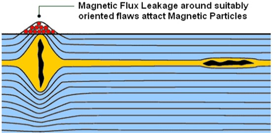
3.1.3.2. Magnetic particles test (MT/MPI)
The MT is also aiming to find mostly cracks in critical areas with irregular shapes. Such as, the turbine blades groves in the roots where the blade slides in the diaphragm. Also, the external/internal cracks in the defected surfaces, near sub-surfaces and wilding. It is faster than the PT by giving immediate results. It can apply to ferromagnetic materials. MT performing as following:
1) Apply magnetic particles to the inspected piece surface.
2) Charge the Yoke device to induce a magnetic field into the inspected piece.
3) Particle groupings where the defects are.
4) Demagnetize and clean the inspected piece.
Fig. 4Penetrate test

a) Red dye penetrant applied

b) Excess penetrant removal

c) White developer applied
Fig. 5Magnetic test
3.1.3.3. Ultrasonic test (UT)
The UT widely used to determine the internal structure flaws of a test piece such as cracks, voids, disbands, etc. by using high frequency sound waves by connecting the UT transducer, which is converting the electrical energy into mechanical vibrations, sound waves in another words. It will be going back from mechanical energy form to electrical so the diagnostic machine can transmit it to readable information. Immersion the testing piece and the transducer by a couplant such as gel, oil or water.
Fig. 6Ultra sound test
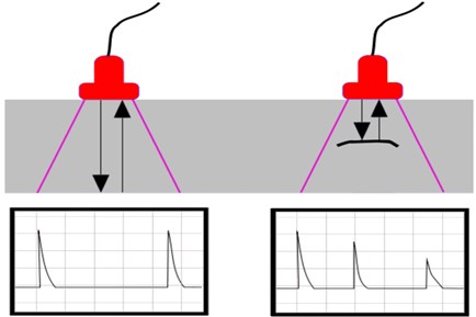
The working principle of UT as shown in the below picture:
1) A sound wave is sent into the test material by the probe. Two signals are present: the first is from the probe's first pulse, and the second is from the back wall echo.
2) In addition to producing a third indication, the defective region also causes the back wall indication's amplitude to decrease.
3.1.4. XRD and EDS investigations
XRD examination is used widely to detect the chemical composition of materials. Therefore, XRD is employed to confirm the chemical composition of turbine blades alloy while EDS is used for the coating layers. Heat tinting, EDS and XRD were commonly carried out to present the harmonized inference that the coating was in good condition [26]. HPTR blades were sectioned to study under SEM. Regions of platinum modified aluminide coating degradation and CM 247 LC (DS) base material cracking were observed which made the particular lot unusable.
4. Failure analysis and discussion
4.1. Failure modes of gas turbine blades
Blades of gas turbine are mainly divided into airfoil, hub, platform, shank, fire tree or dove tail and roots. These parts are shown in Fig. 7 where suction side and pressure side are indicated. Also, details of airfoil section such as, trailing edge, leading edge, chord and its length/ height are shown as well as angle wings.
Fig. 7Parts of gas turbine blades
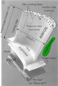
Fig. 8Turbine blades missing body materials
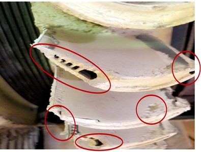
Fig. 9Other turbine blades missing materials from both sides
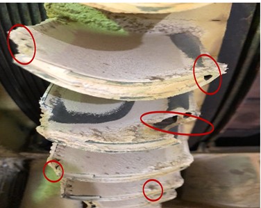
During the fact-finding process, at 77,521 running hours, some of the turbine blades at the first stage discovered damage, missing elements from the blades body (see Figs. 8 and 9), and a thick layer of sulfuric acid (see Fig. 10) accumulated in the cooling airfoils of the blades. The blades were brand new, having been installed following HGPI at 42,000 running hours. This discovery explains the informality of the vibration, which was plainly visible in the trends during pre-outage data collecting.
Fig. 10Sulfuric acid casing corrosion erosion type. Also, accumulated and blocked the cooling air paths
4.2. Types of inspection
The following sections discuss the various sorts of inspections, which differ in scope and interval. The types of inspection may differ in their application and order depending on the operating mode of the gas turbine and the maintenance concept chosen. Table 4 lists the inspection kinds and sequences that are recommended for this engine.
Table 4Maintenance intervals and measures recommend [27]
Type of inspection | Maintenance intervals | |||||||
Type of inspection | Includes the scope of | Equivalent operating hours, (EOH) | Tolerance (in %) | Nonfuel equivalent operation hours, (in nfEOH) | Tolerance (in %) | Starts Ns (in starts) | Tolerance (in %) | Maximum time (in years) |
MI | 8000 | 10 | – | – | – | – | – | |
HGPI | MI | 41000 | 5 | – | – | 650 | 5 | – |
eHGPI | GPI, MI | – | – | – | – | 5 | 12 | |
MO | eHGPI, GPI, MI | – | – | 410000 | 5 | 1250 | 5 | – |
LTE | – | – | 1230000 | 5 | 3000 | 0 | – | |
They are carried out in accordance with equal operating hours or starts:
– The minor inspection, referred to simply as inspection in the following, consists of fact-finding examinations in the engine’s accessible parts and a mostly visual assessment thereof.
– Because minor checks mostly concern components that are exposed to fuel, the EOH counter reading is used to schedule them. The hot gas path inspection (HGPI) encompasses all inspection responsibilities. Furthermore, the turbine section is opened, and the hot gas path components are inspected. Because HGPI mostly involves components that are exposed to fuel, the EOH counter reading is used as the foundation for scheduling.
– An extended-scope hot gas path inspection (eHGPI) includes an HGPI as well as the opening of the outer casing in the compressor section.
– Because the nfEOH counter reading contains extra components that are not exposed to fuel, it is used as the foundation for scheduling eHGPI. The actions done in an extended-scope hot gas path examination are included in a major inspection (also known as a major overhaul, major outage, or MO). Furthermore, the rotor is removed from the engine and unstacked.
– Because the nfEOH counter reading includes more components that are not exposed to fuel, it is used as the basis for scheduling MO. LTE actions go above and beyond the scope of a comprehensive inspection. Nondestructive testing is performed on the gas turbine’s key components. The reading of the nfEOH counter is used to schedule LTE. LTE for fuel-exposed components must be scheduled individually.
– Because of the high degree of pollution in the fuel, the turbine section must also be cleaned at regular intervals.
4.3. Hot gas path inspection (HGPI)
The scope of a hot gas path examination comprises an inspection as well as the replacement of certain hot gas path components. The outer casing of the turbine portion must be removed, as well as the top sections of the turbine vane carriers, including roll-out of the lower section. The compressor and combustor parts are not removed from the engine, and the rotor remains in place. At this time, gas turbine maintenance is planned around the hot gas path components. The gas turbine’s hot gas path components, particularly the turbine blades and vanes, are only designed for a limited-service life. The design allows for enough creep damage because the mechanical design of the blades/vanes is dependent on creep strength. A secondary protective device protects many rows of airfoils from heat corrosion and oxidation. This type of protective system has a restricted coating thickness and a limited reserve of protecting elements like aluminum or chromium. As a result, a protective coating serves as a sacrificial coating; it has a significantly shorter service life than the component it shields and, as a result, must be changed at regular intervals. During the hot gas path inspection, deteriorated turbine blades and vanes are removed and replaced with new or recoated blades; those blades removed are returned to service after recoating. In between hot gas path inspections, the general condition of the blades is checked to ensure reliability. Siemens gas turbine blades, as well as other hot gas path components (casing components exposed to hot gas), are built of high strength superalloys and formed using investment casting techniques. These components withstand varied loads and have varying strengths due to inevitable manufacture tolerances. Furthermore, discontinuities emerge early in the manufacturing process that cannot be detected by examination; they may evolve into faults like as cracks during operation. As a result, these components have extremely distinct characteristics in terms of strength and stress. However, it is ensured that safe, reliable operation is guaranteed until the hot gas route inspection by using thorough quality assurance procedures during fabrication (radiographic examination of blades/vanes, crack examination after every fabrication phase, etc.). Nondestructive evaluation and refurbishment of these components are required during the HGPI to allow safe operation of the gas turbine until the end of the next interval. Because of the unique nature of the components mentioned above, it must be considered that a certain percentage of them cannot remain in service because small, previously undetectable discontinuities have increased and can no longer be repaired. As a result, a certain amount of scrap must be expected during refurbishing. Because turbine blades are only designed to have a limited-service life, blade replacement is required on occasion. The point at which different turbine blade stages must be replaced varies and is shown in Table 6. Furthermore, the four-convolution bellows expansion joint in the turbine’s exhaust area must be inspected and deposits removed as needed to ensure its continuing proper operation. This is necessary because deposits in the turbine section are transferred into the exhaust region during turbine cleaning (see Section “Turbine Cleaning”) and collect in the four convolution bellows expansion joint. This metric has the potential to impact the entire time frame for the inspection, necessitating cautious preparation (see Table. 5).
Table 5Planned outage times for performing the maintenance measures [27]
Type of inspection | Outage times in working days (provided of stipulated conditions are met) |
Turbine washing | 2-3 |
MI | 3-4 1) |
HGPI | 20-28 2) |
eHGPI | 25-30 2) |
MO | 29-41 2), 3), 4) |
LTE | 3) |
1) Taking of a material sample from the inner and mixing casings requires an additional day, i.e., 4 days in total. 2) Applies in cases additional personnel are present to perform maintenance work in the four-convolution bellows expansion joints. Otherwise, ten additional working days must be scheduled. 3) Applies if the fuel oil burners are to be replaced. If they are to be refurbished in site, the measure can be expected to take longer time. 4) NDT on combustion chamber oil lines and on oil supply lines requires approx. 2 additional days, i.e., a total of 41 days. | |
4.4. Hot gas path inspection with extended scope (eHGPI)
In addition to the scope of the hot gas path inspection, the extended-scope hot gas path inspection includes dismantling the combustion chambers and opening the compressor, as well as nondestructive examination and recoating of coated compressor blading and inspection of accessible components per checklist. The gas turbine rotor can be removed from the engine, if necessary, but it is not unstacked. The following arguments support the use of an extended-scope HGPI:
– Opening the casing and cleaning the compressor blades and vanes, as well as performing condition-based recoating or replacement of the compressor blades and vanes, provide an opportunity to remove soiling residues during the extended-scope HGPI, thereby improving the restoration of lost output and efficiency.
– Because of this expanded breadth, minor inspection results (particularly wear) can be addressed quickly, extending the total service life of multiple gas turbine components. As a result, further maintenance procedures are simplified - If planning is focused toward systematic coordination of the many additional operations concurrently, there is no need to significantly lengthen the entire outage duration (see Table 5).
4.5. Major overhaul (MO)
The scope of the major overhaul comprises the extended-scope hot gas path inspection, but it also includes rotor removal and unstacking. The nearly complete dismantling of the gas turbine allows for the refurbishment of coated compressor airfoils, the inspection of otherwise inaccessible locations, and the performance of any repairs considered required based on inspection findings. The gas turbine’s auxiliary systems are inspected, and the fuel valves are disassembled for inspection.
The smoothing of compressor airfoil surfaces, cleaning of gas turbine flow channels, and resetting of radial blade clearances result in a partial restoration of lost efficiency and output. In addition to the steps made on the compressor blading, the fuel oil burner lances must be refurbished or replaced. Replacement is advised since refurbishing on-site requires significant additional effort and hence extends the time required for inspection (see Table 6). Nondestructive testing of the inner casing and mixing casings is also required (see Table 5).
Based on the results of these inspections and the material investigations that will be conducted in preparation for them, continuing operation may be possible as long as no indicators of increased wear are discovered. Material investigations necessitate the collection of material samples during the previous inspection prior to the MO in issue and their visual examination. Due to the length of time required for the fabrication and delivery of new components, such early determination of the state of the materials is required. Replacement of the inner case necessitates at least partial rotor unstacking. There should be no detrimental impact on the duration of the outage if both the inner and mixing casings are replaced. If the inner casing is to be extensively repaired rather than replaced, the time period for the MO must be significantly extended. Auxiliary systems are inspected, function tested, and leak tested to assure proper operation. Decisions on the nature and extent of the significant overhaul should be made at a preparatory meeting conducted at least 24 months before the specified measures are implemented. The recommended scope of maintenance effort is listed in Table 7.
In most cases, the power plant service life is far longer than the design service life of many gas turbine components. It is therefore expedient to implement measures to extend the service life of the highly-stressed components of the gas turbine to also permit continued operation of a gas turbine beyond the end of its nominal service life at high levels of availability, reliability and safety. Installation of upgraded products can even serve to increase plant output and efficiency. These measures must be implemented during the course of a Lifetime Extension outage (LTE) that is performed no later than when the first of the limits for equivalent operating hours or starts stated in Tab. 5 is reached, regardless of which limit is reached first. Consequently, evaluation of the individual components (rotor, casing, compressor blading, auxiliary systems, etc.) is performed at this time to enable formulation of statements on whether these components are suitable for operation until the end of the next major inspection interval. Requalification of rotor components by means of nondestructive evaluation requires unstacking the rotor. Depending on inspection findings (due to increased rotor vibration, indications on the inner casing, etc.), however, it may be necessary to unstack the rotor at an earlier time. The inspection measures required for LTE are described in a separate LTE checklist. As a matter of principle, each LTE is performed together with a major inspection. Due to the fact that an LTE is a relatively time consuming measure which requires extensive planning, in particular as regards determining which work is to be performed, the planning process must begin in good time (about 3 to 4 years prior to the LTE). This lead time is dictated in part by the delivery times for individual components.
4.6. Outage times
If the parameters given below are met, the average outage times listed in Table 5 should be budgeted for completion of the various maintenance steps. The times indicated for taking measures always refer to the time between turning gear shutdown (after the machine has cooled down) and restart. These parameters are two shifts per working day with 10-hour shift, working conditions correspond to industrial standard, fact-finding inspections reveal no significant grounds for objection, a preparatory meeting is held for an HGPI, eHGPI or major inspection at least 24 months before the beginning of the associated measures, scope of the HGPI, eHGPI, or major inspection: dismantling, cleaning, inspections per checklist, replacement of components as stipulated in the refurbishment concept for turbine blading, reassembly and spare parts and reassembly parts are available.
All variations from these parameters (for example, local regulations) must be evaluated separately during planning and may result in higher outage times under certain scenarios. Single-shaft plants, in particular, may require longer outages. The period given for an LTE outage comprises not only the time required for the LTE measures but also the time required for the essential major upgrade measures.
4.7. Refurbishment of 1st gas turbine blades
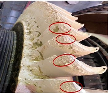
Group of 1st stage gas turbine blades (89SGT6 200E row 1) are employed to refurbishment and examples of these blades are shown in Fig. 11. During the incoming inspection process, sixty-four blades were found to have linear cracking in the blade airfoil that was beyond repair limits and these blades were deemed unrepairable. Twenty-five blades were successfully processed through repair. All repaired blades were sent to the coating vendor and have been processed through final inspections and are acceptable for release to the customer.
Fig. 11Group of 1st stage gas turbine blades (89SGT6 200E row 1)
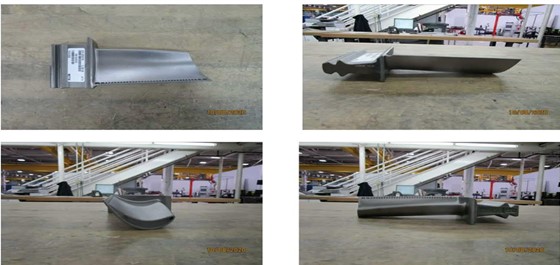
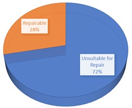
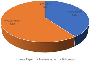
Fig. 12 depicts an overview of the repair process. Twenty-five blades are found to be repairable, accounting for 28 % of the investigated blades, whereas sixty-four blades, accounting for 72 % of the investigated blades, are unsuitable for repair. Ten of the twenty-five repairable blades require serious repair, while fifteen require light repair. There are no blades that require minimal repair.
Fig. 12Overview of repair process. Percentage of a) repairable and b) Unsuitable for repair
a)
b)
5. Conclusions
This study included a compressive investigation and a review of the failure analysis of the gas turbine combined cycle, with an emphasis on the first stage blades. Following accurate calculations obtained through extensive study and review of the studied system, it may be concluded that:
1) The quantity of heat required for complete combustion is accurately determined.
2) The amount of combustion flue gases that can be sufficient to convert the water in the tubes to the amount of steam flue that is sufficient to the steam turbine. The smallest quantity of steam flue can efficiently drive a steam turbine, which is tow gas turbines at full load out of five.
3) This analysis and calculations will be used as a reference for power plants.
The maintenance of the investigated combined gas cycle provided the following two instances of optimal operation time and inspection intervals:
Exemplification 1: The gas turbine is continually run with inspection intervals of 8,000 EOH (the time criterion is reached before the start criterion), and the most recent inspection was completed at 32,800 EOH. The following inspection, in this case a hot gas path inspection, must be completed no later than 41,600 EOH (32,800 EOH + 8,000 EOH (inspection interval) + 800 EOH (10 % “stretc”) and not at the theoretical maximum possible total of 43,050 EOH (41,000 EOH (HGPI interval) + 2,050 EOH (5 % “stretch”)).
Exemplification 2: The gas turbine is operated with 8,000 EOH inspection intervals and a hot gas path inspection interval of 41,000 EOH. At 80,000 EOH, the gas turbine underwent an unplanned inspection. The most recent HGPI was conducted at 41,000 EOH. The next hot gas path inspection, in this case an HGPI, must be performed no later than 41,000 EOH + 41,000 EOH + 5 %, i.e., at 84,050 EOH, and not after the 8,000 EOH inspection interval has elapsed (in other words, it cannot wait until the later time of 80,000 EOH + 8,000 EOH = 88,000 EOH).
On the other side, for 89 blades, refurbishment of first stage blades from base material with SCIOATTM 2231 coating is accomplished. This demonstrated that 64 could not be repaired to specifications and was declared scrap. Furthermore, the following 25 blades require repair: Ten pieces required medium repair, fifteen of them required heavy repair, and no piece required light repair.
References
-
“Types of Corrosion,” https://galvanizeit.org/corrosion/corrosion-process/types-of-corrosion
-
“Forms of Corrosion,” https://www.nace.org/resources/general-resources/corrosion-basics/group-1/eight-forms-of-corrosion
-
C. Celis, S. Peralta, and W. Galarza, “Power augmentation technologies for gas turbines: alternatives for an existing simple cycle power plant in Peru,” in ASME Turbo Expo 2019: Turbomachinery Technical Conference and Exposition, Jun. 2019, https://doi.org/10.1115/gt2019-90136
-
“Magnetic Particle Inspection,” https://www.wermac.org/others/ndt_mpi.html
-
B. Vasilyev, S. Nikolaev, M. Raevskiy, S. Belov, and I. Uzhinsky, “Residual life prediction of gas-engine turbine blades based on damage surrogate-assisted modeling,” Applied Sciences, Vol. 10, No. 23, p. 8541, Nov. 2020, https://doi.org/10.3390/app10238541
-
C.-S. Lin, H.-T. Chiang, C.-H. Hsu, M.-H. Lin, J.-K. Liu, and C.-J. Bai, “Modal verification and strength analysis of bladed rotors of turbine in rated working conditions,” Applied Sciences, Vol. 11, No. 14, p. 6306, Jul. 2021, https://doi.org/10.3390/app11146306
-
C.-Y. Zhang, Z.-S. Yuan, Z. Wang, C.-W. Fei, and C. Lu, “Probabilistic fatigue/creep optimization of turbine bladed disk with fuzzy multi-extremum response surface method,” Materials, Vol. 12, No. 20, p. 3367, Oct. 2019, https://doi.org/10.3390/ma12203367
-
S. Cruz-Manzo, V. Panov, and Y. Zhang, “Gas path fault and degradation modelling in twin-shaft gas turbines,” Machines, Vol. 6, No. 4, p. 43, Oct. 2018, https://doi.org/10.3390/machines6040043
-
Z. Zhang, G. Yang, and K. Hu, “Prediction of fatigue crack growth in gas turbine engine blades using acoustic emission,” Sensors, Vol. 18, No. 5, p. 1321, Apr. 2018, https://doi.org/10.3390/s18051321
-
A. M. Kolagar, N. Tabrizi, M. Cheraghzadeh, and M. S. Shahriari, “Failure analysis of gas turbine first stage blade made of nickel-based superalloy,” Case Studies in Engineering Failure Analysis, Vol. 8, pp. 61–68, Apr. 2017, https://doi.org/10.1016/j.csefa.2017.04.002
-
J. Błachnio, M. Chalimoniuk, A. Kułaszka, H. Borowczyk, and D. Zasada, “Exemplification of detecting gas turbine blade structure defects using the X-ray computed tomography method,” Aerospace, Vol. 8, No. 4, p. 119, Apr. 2021, https://doi.org/10.3390/aerospace8040119
-
A. K. Azmeera, P. Jadhav, and C. Lande, “Microstructure image-based finite element methodology to design abradable coatings for aero engines,” Aerospace, Vol. 10, No. 10, p. 873, Oct. 2023, https://doi.org/10.3390/aerospace10100873
-
S. Mahade, N. Curry, S. Björklund, N. Markocsan, and S. Joshi, “Durability of Gadolinium Zirconate/YSZ Double-layered thermal barrier coatings under different thermal cyclic test conditions,” Materials, Vol. 12, No. 14, p. 2238, Jul. 2019, https://doi.org/10.3390/ma12142238
-
A. Szczepankowski, R. Przysowa, J. Perczyński, and A. Kułaszka, “Health and durability of protective and thermal barrier coatings monitored in service by visual inspection,” Coatings, Vol. 12, No. 5, p. 624, May 2022, https://doi.org/10.3390/coatings12050624
-
Y. Zhang, N. Lu, and W. Qiu, “Optimal data processing method for the application of Eu3+ Photoluminescence Piezospectroscopy in thermal barrier coatings,” Coatings, Vol. 11, No. 6, p. 678, Jun. 2021, https://doi.org/10.3390/coatings11060678
-
S. Chang and K.-Y. Oh, “Contribution of high mechanical fatigue to gas turbine blade lifetime during steady-state operation,” Coatings, Vol. 9, No. 4, p. 229, Mar. 2019, https://doi.org/10.3390/coatings9040229
-
G. Liu et al., “Simulation study on the effect of flue gas on flow field and rotor stress in gas turbines,” Energies, Vol. 14, No. 19, p. 6135, Sep. 2021, https://doi.org/10.3390/en14196135
-
S.-P. Zhu, P. Yue, Z.-Y. Yu, and Q. Wang, “A combined high and low cycle fatigue model for life prediction of turbine blades,” Materials, Vol. 10, No. 7, p. 698, Jun. 2017, https://doi.org/10.3390/ma10070698
-
V. Naga Bhushana Rao1, N. Niranjan Kumar, and K. Bala Prasad, “Failure analysis of gas turbine blades in a gas turbine engine used for marine applications,” International Journal of Engineering, Science and Technology, Vol. 6, No. 1, pp. 43–48, 2014.
-
Rajni Dewangan, Jaishri Patel, Jaishri Dubey, Prakash Kumar Sen, and Shailendra Kumar Bohidar, “Gas turbines blades-a critical review of failure on first and second stages,” International Journal of Mechanical Engineering and Robotics Research, Vol. 4, No. 1, pp. 216–223, 2015.
-
N. Holtham and K. Davami, “A review of laser peening methods for single crystal Ni-based superalloys,” Metals, Vol. 12, No. 9, p. 1414, Aug. 2022, https://doi.org/10.3390/met12091414
-
Poppy Puspitasari, Andoko Andoko, and Pradhana Kurniawan, “Failure analysis of a gas turbine blade: A review,” in IOP Conference Series: Materials Science and Engineering, 2021, https://doi.org/10.1088/1757-899x/1034/1/012156/meta
-
F. Mevissen and M. Meo, “A review of NDT/structural health monitoring techniques for hot gas components in gas turbines,” Sensors, Vol. 19, No. 3, p. 711, Feb. 2019, https://doi.org/10.3390/s19030711
-
A. Lienert and O. Schmoch, “Gas turbine technology,” Mechanical Design Union AG, West Germany.
-
Barhm Abdullah Mohamad and Abdelsalam Abdelhussien, “Failure analysis of gas turbine blade using finite element analysis,” International Journal of Mechanical Engineering and Technology (IJMET), Vol. 7, No. 3, pp. 299–305, Jun. 2016.
-
R. Rajendran, M. D. Ganeshachar, Jivankumar, and T. Mohana Rao, “Condition assessment of gas turbine blades and coatings,” Engineering Failure Analysis, Vol. 18, No. 8, pp. 2104–2110, Dec. 2011, https://doi.org/10.1016/j.engfailanal.2011.06.017
-
“Gas Turbine Time Schedule for Maintenance,” Siemens Company, 2020.
About this article

The authors have not disclosed any funding.
The datasets generated during and/or analyzed during the current study are available from the corresponding author on reasonable request.
The Contribution of each individual co-author is equal.
The authors declare that they have no conflict of interest.
