Abstract
In this study, performance verification tests were conducted on a small turbojet engine, during which a failure occurred at the root of the centrifugal compressor blades, which are made of aluminum alloy. A detailed disassembly and inspection was carried out to reveal the reason of the failure. It was found that the failure of one blade at the root led to jamming of other blades. Then the jammed blades experience sever rubbing and contact with the intake duct. Experimental measurements of material properties and a retrospective examination of the manufacturing process revealed that the yield strength of the material was lower than the design value, and the fillet radius at the blade root was smaller than specifications. The root cause of the fatigue failure of the compressor blades in this incident was attributed to substandard machining quality and material properties, which leads to crack initiation and fatigue propagation until failure occurred. The experience of identifying the root cause would provide engineering guidance for other small turbojet engines.
Highlights
- The distribution of multiple crack sources concentrated on the concave and convex sides of the blade root.
- The stress of the blade root is extremely sensitive to the radius of the blade root fillet.
- Cracks of the blade root initiated from machining marks.
1. Introduction
In recent years, unmanned aerial vehicles (UAVs) have achieved significant success in regional conflicts, attracting widespread attention both domestically and internationally. Small turbojet engines, which are used as the propulsion systems, would directly impact the performance and functionality of UAVs, determining their stability and reliability during operation. The centrifugal compressor was widely applied in these small turbojet engines to provide most of the thrust. However, the blades of the centrifugal compressor would experience substantial centrifugal forces as well as very complex aerodynamic loads. Thus, materials with high specific strength and specific stiffness, such as aluminum alloys and titanium alloys, are often selected for these blades to guarantee high aerodynamic efficiency. Also, these blades have relatively small thicknesses, making them susceptible to fracture [1-3].
This work aims to determine the cause of the blade fracture by conducting a comprehensive analysis of the chemical composition, metallographic structure, mechanical properties, and macroscopic and microscopic features of the fracture surface of the broken blades. The experience of identifying the root cause would provide engineering guidance for other small turbojet engines.
2. Experimental methodology and results
2.1. Macroscopic analysis
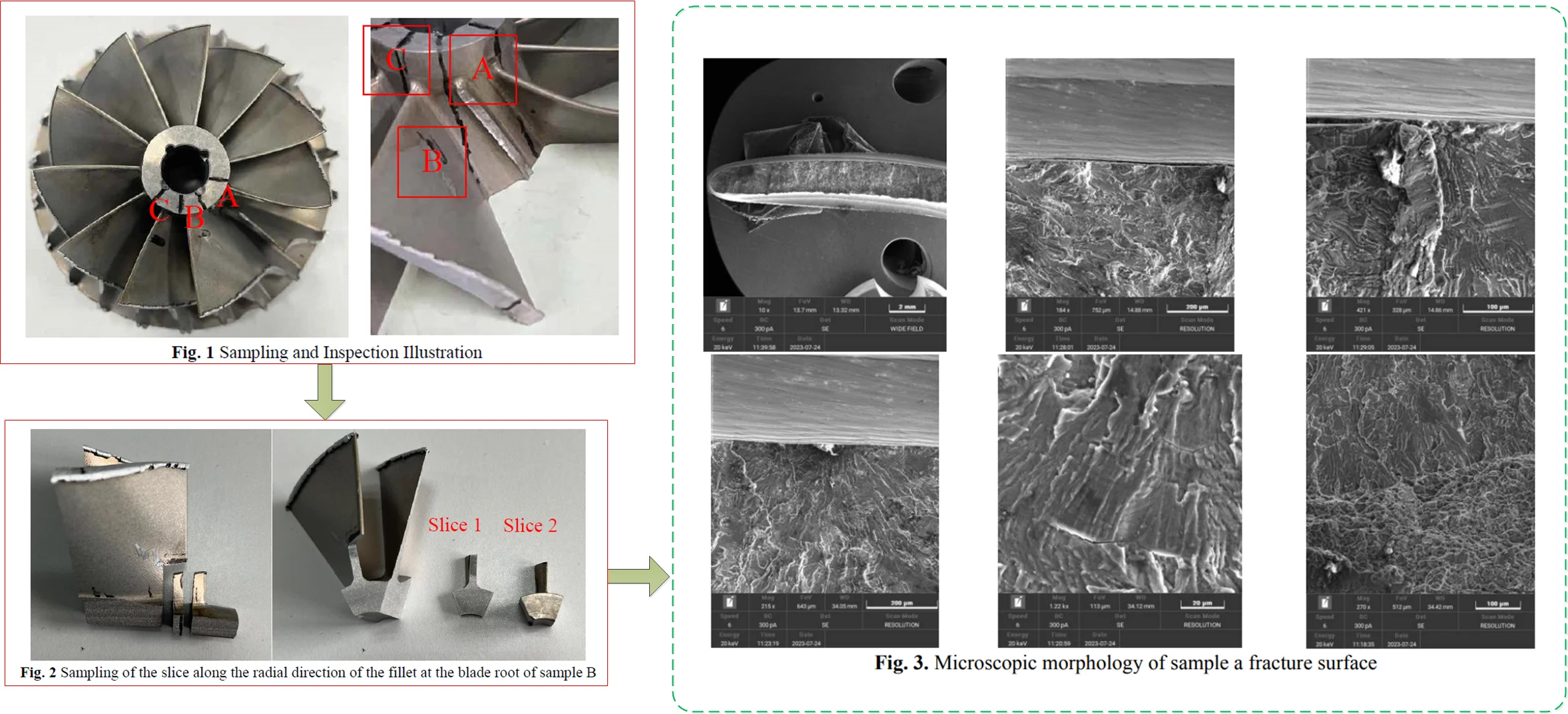
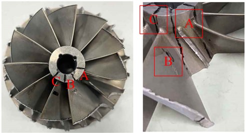
A small turbojet engine (designated as “Engine I”) is subjected to a test run of 2.5 hours. During which, an abnormal vibration signal was detected, thus prompting halting of the experiment. Subsequently, disassembly and inspection of the entire engine were carried out, revealing the fracture of one of the large blades at the root of the centrifugal compressor. Additionally, other blades exhibited clear signs of wear and tear, as depicted in Fig. 1. Moreover, traces of impact were observed on the turbine rotor, indicating contact with the fractured blade from the compressor rotor.
To replicate this incident, Engine II was randomly picked with the centrifugal compressor from the same batch. Under an identical test schedule, Engine II ran smoothly for 2 hours before the abnormal vibration signal detected, which lead to the cessation of the experiment. Subsequent disassembly and inspection of Engine II revealed a similar fracture at the root of the centrifugal compressor blade.
For better observation, linear cutting was performed at the fracture site of the centrifugal compressor and assigned sample labels accordingly. Sample A represents the fractured blade, and adjacent to sample A, two other large blade roots exhibited small cracks. The relative positions of these three large blades are illustrated in the right side of Fig. 1.
Fig. 1Sampling and Inspection Illustration
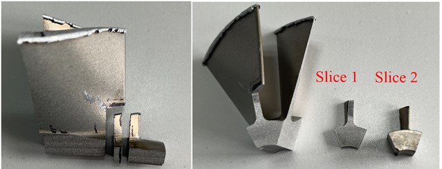
Visual inspection revealed that there were scattered cracks on the surface of the blade roots of samples B and C while no cracks were found on other blades, only wear traces were observed. At the fillet of sample B, cross-sectional slices were prepared along the crack’s radial direction, resulting in Slice 1 and Slice 2, as shown in Fig. 2.
Fig. 2Sampling of the slice along the radial direction of the fillet at the blade root of sample B
2.2. Microscopic analysis
Microscopic observations of the blade fracture surface were conducted using a scanning electron microscope (SEM). As shown in Fig. 3(a), (c) and (d), the fracture lines on sample A converge at various locations on the blade's concave side, exhibiting characteristics of multiple crack origins. No apparent metallurgical defects were observed in these origin regions. Energy dispersive X-ray spectroscopy (EDS) analysis revealed that the oxygen content in this area was significantly higher than in other regions, with no abnormal concentrations of other elements.
Fig. 3(b) illustrates the presence of an unusual machining mark on the concave side of the blade, with a depth of approximately 5.3 μm. In the expansion zone, as shown in Fig. 3(e), distinct fatigue striations were observed.
As depicted in Fig. 3(f), the boundary between the fatigue propagation region and the instantaneous fracture region was evident, with features of dimples observed in the instantaneous fracture region. Multiple crack initiation sites occurred on one side of the blade, and they propagated through the blade until penetrating completely.
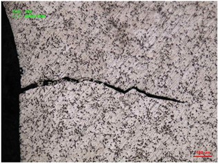
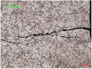
Microscopic examination of slice B revealed that: Observations on Slice 1 indicated that the crack length had reached approximately 50 % of the blade’s thickness. Furthermore, in the vicinity of the primary crack in slice 2, secondary cracks were observed.
Fig. 3Microscopic morphology of sample a fracture surface
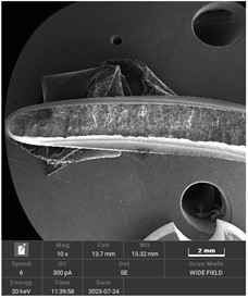
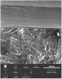
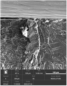
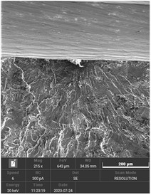
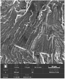
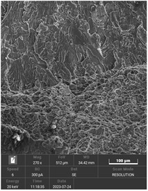
Fig. 4Cracks along the thickness direction of sample B blade
2.3. Material analysis
Chemical composition analysis was conducted on samples taken from the matrix of the fractured aluminum alloy 2A70 blade. The results are shown in Table 1, and the chemical composition meets the technical specifications requirements.
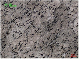
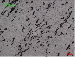
For samples B and C, metallographic samples were prepared and polished, followed by etching with a corrosion agent. Subsequently, structural analysis was performed using a metallographic microscope. As shown in Fig. 5, the grain boundaries are clear, and no signs of overheating or burning are observed.
Table 1Chemical composition
Si | Mn | Ni | Ti | Cu | Fe | Mg | Zn | |
Standard | < 0.35 | < 0.2 | 0.9-1.5 | 0.02-0.1 | 1.9-2.5 | 0.9-1.5 | 1.4-1.8 | < 0.3 |
Measured | 0.08 | 0.01 | 1.16 | 0.06 | 2.36 | 0.90 | 1.62 | 0.01 |
Fig. 5Metallographic image of sample B
2.4. Mechanical property analysis
For the mechanical property testing, samples were obtained from unused centrifugal compressor of the same batch. Due to the limitations of raw material size, four sheet-shaped tensile specimens were taken. The testing method followed the GB/T 228.1-2010 standard. An electronic tensile testing machine was used to measure the mechanical properties of the material. Three specimens were used for data measurement, and one was used as a compensation piece during the measurement process. Table 2 presents the test results, with an average yield strength of 267 MPa and an average tensile strength of 370 MPa.
Fig. 6Sampling region and geometric dimensions of tensile test specimens
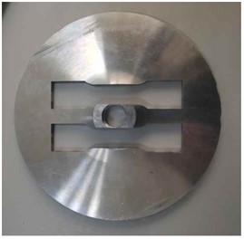
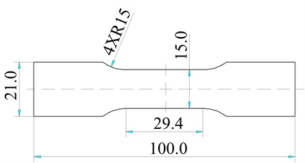
Table 2Chemical composition
Sample | Width / mm | Thickness / mm | Cross section / mm2 | Failure load / KN | Yield strength / MPa | Tensile strength / MPa |
1 | 15.01 | 1.48 | 22.21 | 8.298 | 268.01 | 373.53 |
2 | 15.03 | 1.50 | 22.55 | 8.396 | 269.51 | 372.41 |
3 | 15.04 | 1.51 | 22.71 | 8.242 | 263.49 | 363.00 |
Mean | 267 | 370 | ||||
Standard deviation | 3.1 | 5.8 | ||||
2.5. Stress analysis
Analysis of the centrifugal compressor can be performed using a cyclically symmetric model. The FEM model of the blade was established with ANSYS. And the stress analysis was conducted under the operating speed. It was found that the maximum equivalent stress at the blade root on the concave side is sensitive to changes of the fillet radius. The simulation results are provided in Table 3. The equivalent stress is reduced by 9.5 % when the fillet radius is increased from 1.5 mm to 1.7 mm. In areas with high stress, under the action of alternating loads, crack initiation and even crack propagation are more likely to occur. The crack source region corresponds closely to the location of the maximum stress region at the blade root, as shown in Fig. 7.
Fig. 7Equivalent stress contour under operating speed
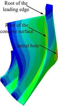
Table 3The relationship between the maximum stress (root of the concave side) and the radius of the fillet
Radius / mm | 1.5 | 1.7 | 2.0 | 2.5 |
Stress / MPa | 245.7 | 222.3 | 208.2 | 192.5 |
3. Discussion
Macroscopic and microscopic analysis results indicate that the area of the fracture region, particularly the instantaneous fracture zone, is relatively large. The failure mode of the blade can be attributed to fatigue fracture under high stress. Multiple crack sources are observed, distributed on both the concave side and the convex side of the blade root, suggesting a correlation between crack initiation and fatigue failure with high stress.
Mechanical test results reveal that the material used in the centrifugal compressor rotor has a yield strength of 267 MPa and a tensile strength of 370 MPa. However, the yield strength of the material is 11 % lower than the design requirement of 300 MPa, indicating that the margin of strength is smaller than the design value by 11 %.
Finite element analysis demonstrates that the region of maximum stress in the blade situated at the fillet of the concave side, and the equivalent stress is highly sensitive to the fillet radius. Cracks originate from both the concave and convex sides of the blade root. Upon tracing back to the manufacturing process, it was found that the original design specified a fillet radius of 1.7 mm with a free tolerance of ±0.2 mm. However, during actual machining, an alloy tapered milling cutter was used, resulting in an actual fillet radius of 1.5 mm with uneven surface quality in the fillet region, accompanied by noticeable tool marks.
Therefore, it is advised to select a larger fillet radius thus ensuring the quality of the machined surface to reduce the risk of crack initiation and fatigue failure, especially in high-stress regions.
4. Conclusions
The fundamental reason behind the fracture of the centrifugal compressor blade in this incident can be attributed to the initiation of cracks in high-stress zones and subsequent fatigue propagation failure. The analysis of this event has made it clear that the high-stress regions played a pivotal role in the blade's failure.
Through macroscopic and microscopic analyses, we can confirm that the area of instantaneous fracture on the fracture surface is relatively large, further validating the failure mode of the blade as fatigue fracture under high-stress conditions. Moreover, the distribution of multiple crack sources, particularly concentrated on the concave and convex sides of the blade root, further underscores the connection between crack initiation and high-stress regions.
To prevent similar incidents, following recommendations are proposed:
1) Increasing the size of the fillet radius of the blade root: Consider increasing the size of the blade root fillets to reduce the sensitivity of high-stress regions and mitigate the risk of crack initiation. This can be achieved through a redesign of the blade structure or manufacturing processes.
2) Enhancing material mechanical property requirements: Raise the mechanical property requirements for blade to guarantee sufficient strength reserves, thus improving fatigue resistance under high-stress conditions.
3) Manage the manufacturing process strictly: During the manufacturing process, adherence to design requirements is essential, especially in the fabrication of blade root fillets. Special attention should be paid to the abnormal machining marks.
References
-
G. Liu and D. Liu, “Fracture failure analysis for blade root of compressor,” (in Chinese), Aeroengine, Vol. 42, No. 3, pp. 93–97, 2016, https://doi.org/10.13477/j.cnki.aeroengine.2016.03.018
-
Zhang Zaide, “Fracture fault analysis and test verification of engine compressor blades,” (in Chinese), Failure Analysis and Prevention, Vol. 14, No. 4, pp. 258–261, 2019, https://doi.org/10.3969/j.issn.1673-6214.2019.04.008
-
Z. Li, “Fracture analysis on compressor blade of aero-engine,” (in Chinese), Failure Analysis and Prevention, Vol. 12, No. 2, pp. 112–115, 2017, https://doi.org/10.3969/j.issn.1673-6214.2017.02.008
-
Li Wei, “Common characteristics in failure analysis of aeroengine blade,” (in Chinese), Gas Turbine Experiment and Research, Vol. 15, No. 2, pp. 28–30, 2002, https://doi.org/10.3969/j.issn.1672-2620.2002.02.008
-
B. Wu, Y. Luo, and L. Li, “Study on shot peening strengthening process of aluminum alloy rotor,” (in Chinese), Gas Turbine Experiment and Research, Vol. 15, No. 2, pp. 28–30, 2002, https://doi.org/10.3969/j.issn.1673-6214.2017.02.008
-
X.-F. Ma, “Shot peening-paint process of aluminum alloy compressor blades of certain engine,” (in Chinese), China Surface Engineering, Vol. 24, No. 3, pp. 93–96, 2011, https://doi.org/10.3969/j.issn.1007-9289.2011.03.019
About this article

The authors have not disclosed any funding.
The datasets generated during and/or analyzed during the current study are available from the corresponding author on reasonable request.
The authors declare that they have no conflict of interest.
