Abstract
The bearing failure seriously affects the normal operation of the motor. In this paper, the early damage of bearing wear caused by the shaft current in the operating state of the variable frequency motor is proposed. From the perspective of the bearing capacitance storage capacitor charge, the method based on analyzing the relationship between pitting pit size and shaft current per unit area of bearing track surface is proposed, so that the model can directly judge whether the bearing is in an absolutely safe running state. In this paper, the description model between the size of the pitting pit per unit area of the bearing track surface and the mechanical and electrical parameters is derived based on the assumption that the charge required for the formation of pitting pits per unit area of the bearing track surface. It is shown that the shaft current can promote the bearing to produce pitting pit, which leads to the early damage of the bearing, and the size of the pitting pit is positively related to the shaft current. Matlab/Simulink simulation verifies the correctness of the description model.
1. Introduction
Pitting wear on the bearing surface will increase bearing friction and reduce bearing life. In severe cases, the motor will stop and affect the safe operation of the drive system [1, 2]. Roylance and Hunt suggested relationships between Wear mechanism and wear morphology were due to various factors. pitting wear was due to abrasion, cutting (mechanical), fatigue and adhesion [3].
Few papers have, however, reported on the effects of electrical currents and mechanical parameters combined with bearings during safe operation of bearings. In this paper, the charge energy of the pitting wear formed in the unit area of the track surface during bearing operation is studied, and according to Griffith's continuous theory, the description model between the size of the pit wear formed per unit area and the mechanical - electrical parameters is derived.
Therefore, we can directly determine the running state of the bearing by analyzing the size of the pitting wear formed.
2. Energy demand model for forming pit diameter per unit area
When the shaft current passes through the bearing for a long time, pits will be formed on the surface of the bearing track [4-6]. Pitting pit. The Pitting pit increases the bearing friction. and under the combined action of current and contact stress, the Pitting pit will gradually extend to the whole working area of the track. In this paper, it is assumed that the width of the rail surface of the bearing is , the diameter of the pitting pit per unit area of the track surface is , and the energy of forming the pitting pit per unit area is . According to the theory of force deformation and ductility of bearing materials, when the smooth track surface is plastically deformed to form hemispherical pitting pit of diameter is , the coefficient of extension deformation of the material is 100-160 % [4]. Then the diameter of the pitting pit and the diameter of the pitting pit per unit area of the track surface satisfy the following relationship:
In general, the deformation coefficient can reflect the magnitude of the stress to a certain extent, and when ≥ 1.5, the stress is linear with the deformation coefficient [4]. Considering that the formation of pitting pits on the surface of the track is actually plastic deformation of the material, if 1.5 is preferred, then:
During the operation of the bearing, assuming that the speed of the bearing is constant, the track surface will form a number of pitting strips which is formed by a plurality of pitting pits. assuming that the diameter of the inner ring of the bearing is , the spacing between the pitting strips is , then the energy required for a pitting zone is:
It can be seen that is a function of the diameter of the pit, we can get the derivative:
when , it can get:
According to the Hertz point contact theory, the contact between the rolling element and the raceway is an elastic point contact [7, 8]. Under the action of the radial force, the contact will take place elastic deformation and its shape is ellipse. The calculation formulas of the long semi-axis a and the short semi-axis b of the bearing rolling element and the elliptical contact surface of the inner ring are as follows [9]:
If the load carrying capacity of the rolling element is , then the calculation formula is [9]:
where is the strain force, is pure radial force, then the simultaneous Eq. (4) and Eq. (5), we can get:
3. Energy model for bearing equivalent capacitance charge accumulation
From the circuit point of view, when the voltage changes, the bearing capacitance is charged and discharged, and there will occur charge and discharge current .When the shaft voltage exceeds the breakdown voltage of the oil film, the oil film is broken, and the discharge of the bearing capacitance leads to the emergence of the current [10, 11]. Under the long-term action of the shaft current, the orbital surfaces of the inner and outer rings will form dense pitting damage. The equivalent circuit model is shown in Fig. 1.
Fig. 1The equivalent circuit model
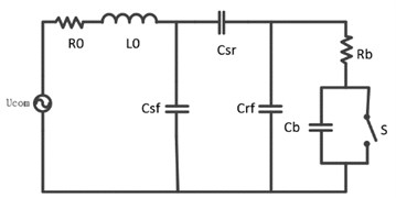
The bearing is equivalent to a discharge capacitor after penetrating the oil film. The discharge energy depends on the contact theory between the objects, considering the heat loss during operation, which is equivalent to half of the energy acting on the bearing track [8, 12], so the effective energy acting on the bearing track is
Assume that the area of the bearing track surface is: , then per unit area of the effective energy is:
Therefore, the simultaneous Eq. (6) and Eq. (8), the energy required of per unit area is:
and then the simultaneous Eq. (9), we can get:
This description model shows the relationship between the diameter d of the pitting pit per unit area formed and the shaft voltage and the shaft current where is the elastic modulus of the bearing, is the load force applied during the operation of the bearing, and the bearing inner ring is , the diameter of the outer ring is , and is the long axis and the short axis of the ellipse formed by the contact between the rolling element and the track during the running of the bearing respectively. The description of the model shows that the size of the pitting pit varies with the shaft voltage, the shaft current, the applied load force and the time. When the applied load force is constant, the diameter of the pitting pit will increase as the shaft current increases. In order to verify the variation rule of pitting pit, the motor system simulation model is built on the Matlab/Simulink.
4. Simulation analysis of current damage description model
The motor system simulation model is established in Matlab/Simulink, and We select the commonly used 6208 Deep Groove Ball Bearing, the simulation system diagram is as follows.
Fig. 2PWM simulation system
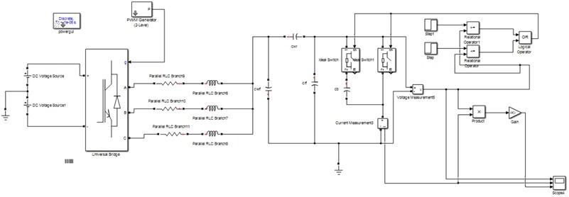
The design parameters of simulation analysis are as follows: the bearing outer diameter is 80 mm, the bearing inner diameter is 40 mm, the bearing width is18 mm, Young’s modulus of elasticity is 2.25×10¹¹ Pa. The is 500 N and Hertzian theoretical contact area is 1.17. The relationship between the formation of pitting pits under different shaft currents is simulated by changing the shaft voltage. The simulation results are shown in the following Table 1.
Table 16208 bearing simulation results
Shaft voltage / V | 3.748 | 4.123 | 4.497 | 4.872 | 5.247 | 5.997 | 6.746 | 7.496 | 8.245 | 8.995 |
Shaft current / A | 0.187 | 0.206 | 0.225 | 0.244 | 0.262 | 0.3 | 0.337 | 0.375 | 0.412 | 0.45 |
Pitting surface / mm | 1.705 | 2.062 | 2.454 | 2.881 | 3.341 | 4.364 | 5.523 | 6.818 | 8.25 | 9.818 |
Pitting pit / mm | 0.989 | 1.196 | 1.423 | 1.671 | 1.938 | 2.531 | 3.203 | 3.954 | 4.875 | 5.694 |
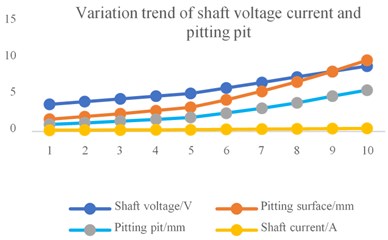
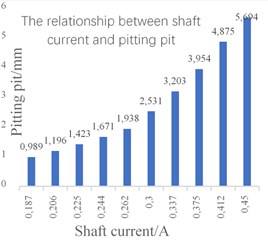
When the shaft voltage is set from 3.748 V to 8.995 V, the measured shaft current fluctuates in the range of 0.187 A to 0.45 A. and the pitting pit diameter formed per unit area of the track surface extends from 1.705 mm to 9.818 mm. The formed semi-ellipsoid pitting pit diameter expands from 0.989 mm to 5.694 mm. The specific values are as shown in the above Table 1, and we can get the result in the Fig. 3(a) of Variation trend of shaft voltage current and pitting pit, and Fig. 3(b) of the relationship between shaft current and pitting pit.
Fig. 3a) Variation trend of shaft voltage current and pitting pit, b) the relationship between shaft current and pitting pit
a)
b)
It can be seen from the simulation results that When the load is constant, the diameter of the pitting pit formed on the surface of the track increases with the increase of the shaft current. The long-term action of the shaft current will increase the pitting wear caused by the bearing. The simulation results verify the accuracy of the model.
5. Conclusions
1) The bearing will form pitting wear on the track surface due to the continuous action of the shaft current under normal operating conditions. The diameter of the pitting pit per unit area of the track surface is related not only to the potential difference and the shaft current on the working surface of the bearing, but also related to the parameters of the bearing itself (the diameter of the inner and outer rings, the width of the track surface).
In addition, changes in shaft voltage and shaft current can exacerbate the formation of pitting pit. The simulation results further show that the pitting pit diameter is positively correlated with the shaft current of the motor.
2) The establishment of this description model provides a theoretical basis for analyzing the size of the pits on the bearing surface during the operation of the variable frequency motor. It is simple and convenient to judge whether the bearing is in an effective operation state by analyzing the size of the pit. This method has certain reference value for engineering technical problems.
References
-
Bai Bao Dong, Liu Wei Feng, Wang Yu PWM drive induction motor shaft voltage bearing current. Journal of Electrical Engineering, Vol. 28, Issue 2, 2013, p. 434-440.
-
Liu Rui Fang, Lou Zhuo Fu, Ma Xi Ping Calculation model of bearing equivalent capacitance and resistance in motor shaft current problem. Chinese Journal of Electrical Engineering, Vol. 34, Issue 15, 2014, p. 2430-2437.
-
Roylance B. J., Hunt T. The Wear Debris Analysis Handbook. 1st ed., Coxmoor’s Machine Publishing Company, 1999, p. 21-24.
-
Wang Youming Controlled Rolling and Controlled Cooling of Steel. Metallurgical Industry Press, 2018.
-
Li Qing Song Diagnosis of Locomotive Traction Motor Bearing Fault Based on Stator Current Analysis. M.E. Thesis, Beijing Jiao Tong University, 2011.
-
Wang Ling Yun, Liu Rui Fang Analysis and Calculation of Bearing Current of Electric Locomotive Bearing Shaft Box. M.E. Thesis, Beijing Jiao Tong University, 2009.
-
Meng Xian Wen Research on Current Damage of Wind Turbine Bearing Shaft. M.E. Thesis, Hunan University of Science and Technology, 2016.
-
Jiang Yan Zhen, Chen Xi You, Xu Dian Guo A feedforward active filter for eliminating motor end shaft voltage and bearing current in PWM inverter drive system. Journal of China Electrical Engineering, Vol. 23, Issue 7, 2003, p. 134-138.
-
Wan Jian Ru, Yu Hua Jun Variable frequency motor bearing failure mechanism analysis. Bearings, Vol. 8, 2002, p. 24-27.
-
Wan Jian Ru, Yu Hua Jun Research on the influence of motor characteristic change of PWM variable frequency speed control system on overvoltage. Journal of Electrotechnical Technology, Vol. 17, Issue 2, 2002, p. 24-28.
-
Busses D., Erdman J., Ker Kman R. J. Bearing current their relationship to PWM drives. IEEE Transactions on Power Electronics, Vol. 12, Issue 2, 1997, p. 243-252.
-
Wan Jian Ru, Sun Yang Jian, Yu Hua Jun PWM mechanism analysis of motor shaft current generation under PWM pulse. Automation of Electric Power System, Vol. 18, 2003, p. 22-25.
About this article

Financial support from National Natural Science Foundation of China (51575178), financial support from Hunan Natural Science Foundation of China (2018JJ2120).
