Abstract
The majority of applications of active magnetic bearings were still based on conventional PID control system. The 2 DOF (two-degree-of-freedom) PID controller can solve the problem of the optimal tuning for the disturbance response and the one for the set-point response. A 2 DOF PID control for active magnetic bearings (AMB) is discussed in this paper. According to fundamental principle of finite element mathematical model of the flexible shaft is presented. The controlled plant of 2 DOF PID mathematical model is determined. Control parameters of the 2 DOF PID systems for active magnetic bearings are discussed. The active magnetic bearing laboratory system is shown. The obtained experimental results show that 2 DOF PID controller of the active magnetic bearings-flexible rotor system is stable through the first critical speed.
1. Introduction
Since the 1930s scientists have begun using active electromagnets systems for high-speed ultracentrifuges [1]. But magnetic bearings did not become a practical alternative to rolling element bearings, for that, active magnetic bearings are physically unstable, and only advanced controllers and algorithms for active magnetic bearings systems can provide proper stiffness and damping. Until the last decade, magnetic bearing technology has found wide applications for levitating and high-speed rotor dynamic systems in many applications because of advances in micro-processing controllers that allow for confident and robust active control [2]. Control of magnetic bearings has been studied in recent years. The most important modern sophisticated control approaches used for active magnetic bearings are, such as linear PID controllers [3, 4], gain scheduled control [5], adaptive control [6, 7], robust H∞ control [8], robust sliding mode control [9], robust control via Eigen structure assignment dynamical compensation [10], optimal control [11], dynamic programming control [12], genetic algorithm control [13], fuzzy logic control [14, 15], feedback linearization control [16], time-delay control [17], control by transfer function approach [18], μ-synthesis control [19]. Despite rapid development of advanced control algorithms for active magnetic bearings, the main control of active magnetic bearing industrial applications were based on conventional decentralized PID controllers.
PID control plays a leading role in AMB as its easy algorithm implementation, good dynamic and static performance. However, conventional PID controller has only one-degree freedom and generally cannot obtain better dynamic responses in both the command tracking and load disturbance regulation characteristic. In 1963, Horowitz [20] stated that a 2 DOF control system naturally has advantages over a 1 DOF control system. But Horowitz's work did not attract a general attention from engineers until after two decades. In 1984 Araki’s research exploited the advantages of the 2 DOF structure for PID control systems [21, 22]. Consequently, 2 DOF PID controllers were proposed for various industrial use [23, 24], and further studies were made about the structure and optimal parameters of 2 DOF PID control [25-26].
This paper studies 2 DOF PID control design for an AMB flexible rotor system. The 2 DOF PID control has two parameters to be designed separately. 2 DOF PID can overcome the shortage of conventional 1 DOF PID and improve the performance of the controller of AMB. One of two parameters in 2 DOF PID control can make the command tracking characteristic best, the other can make the load disturbance regulation characteristic best.
In second section of the paper the mathematical model of active magnetic bearings for flexible shaft will be presented. The model of flexible rotor system is constructed based on the finite element method. The obtained mathematical model will be used for the control system design and numerical evaluation of 2 DOF PID control algorithms. In third section a short survey of the 2 DOF PID control algorithms used for active magnetic bearing control will be shown. Because the main of industrial applications of active magnetic bearings were still used decentralized PID control system, the new rule-based procedure for 2 DOF PID control synthesis will be presented. In fourth section the laboratory active magnetic bearing system for control algorithms evaluation will be described. The robustness of the 2 DOF PID control system on dynamics and parameter variations will be analyzed by means of simulations and experiments.
2. Finite element modeling of flexible rotor systems
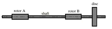
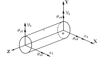
The flexible shaft is constructed in terms of beam-type finite element model as Fig. 1, the shaft has four degrees of freedom. The elastic element vector of displacement and rotation assigned to element can be arranged in the following:
The mechanical system of a rotating shaft can be described as the following equation [30]:
and are the mass matrices and gyroscopic matrices including that of the shaft and the rigid discs. is damping matrix, is stiffness matrices of the shaft. is the vector of gravity force, and is imbalance force for the complete rotor system.
Fig. 1Rotor system and shaft element
a)
b)
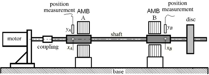
As illustrated in Fig. 2, active magnetic bearings are combined controller and actuators. The actuators comprise 4 pole pair electromagnets, switching power amplifiers, position sensor, and control system. The amplifiers convert the control currents into the electrical currents in the coils. These currents produce the magnetic field in the electromagnet, which produces the corresponding magnetic force. The deviation of rotor and from the and sensor are used by controller as feedback signal. The controller provides the control current and in the electromagnet. The electromagnet coils to produce magnetic force and which suspend the rotor. The forces of magnet are to be [19, 20]:
where and denote the current stiffness, and are position stiffness, and are the control current, and are the position respectively.
In which:
where is the force acting angle, equals to (half the angle between the poles of an electromagnet); is the coil turns; is the air gap, is the magnetic permeability of a vacuum, equals to 4×10⁻⁷ Vs/Am; is the length of air gap.
Fig. 2Configuration of flexible rotor with unblance disks supported by active magnetic bearing
3. 2 DOF PID controller design
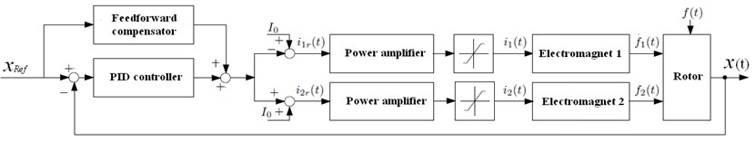
A general form of the 2 DOF PID controller is shown in Fig. 3, where the controller consists of two components and . is the conventional PID element, and being an appropriate element satisfying the second criterion. The transfer function from the disturbance to the controlled variable is assumed to be different from the transfer function from the manipulated variable to . is called the serial (or main) compensator and the feedforward compensator. In this case, and are given by:
Block diagram of the 2 DOF PID control system for one mechanical degree of freedom is given in Fig. 4 and Fig. 5 where the meanings of the symbols are as follows:
– reference position displacement of the rotor,
– transient position displacement of the rotor,
– reference currents of the magnetic coil,
– actual currents of the magnetic coil,
– electromagnetic forces on the rigid body.
For every radial active magnetic bearing two control systems on Fig. 5 are used – for horizontal and for vertical position control respectively. Both control systems are separately.
Fig. 32 DOF control system
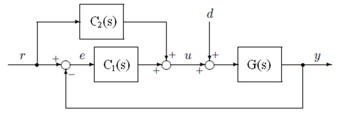
Fig. 4Principle of electromagnetic levitation for active magnetic bearing system
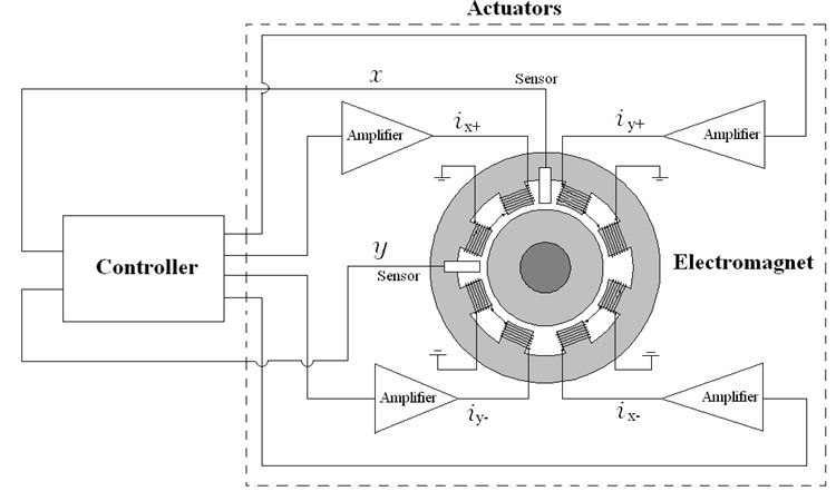
Fig. 5Control structure for active magnetic bearing system
4. Control implementation
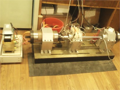
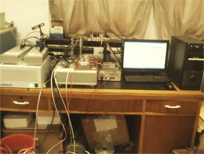
In Fig. 6, in the experiment, a Dspace DS1103 controller board with a DS4003 digital input/output system board is used to test the digital position control for active magnetic bearings. A Dspace DS1103 PPC controller board is used to test the digital position control for active magnetic bearings. The position controllers are realized in parallel form with additional feedback blocks. The position measurements are performed using four CWY-DO-81 contact-less eddy current displacement sensors. The A/D converters resolution is below 1 μm. DS1103 PPC controllers are used in the current control loops along with current sensors and analogue filters.
Fig. 6Principle of electromagnetic levitation for active magnetic bearing system
a)
b)
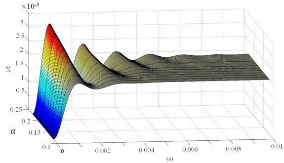
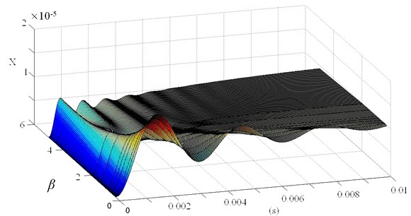
Fig. 72 DOF PID controller parameter of electromagnetic bearing system step response
a)
b)
5. Experimental results
This section presents the experimental results of the 2 DOF PID controller of active magnetic bearings. In the performed simulations a dynamic mathematical model given by Eqs. (2), (3), (4) and (5), (6) was considered, while the influence of power supply was not taken into account.
The formulae of the feedback type compensators given in Eqs. (5), (6) indicate that the 2 DOF control system is obtained by moving some portions of the proportional and the derivative components of the conventional PID controller to the feedback path and the amounts of the portions to be moved are given by and . Fig. 7 illustrates this situation of and , in which the set-point response of the 2 DOF system is shown.
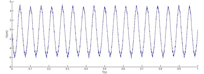
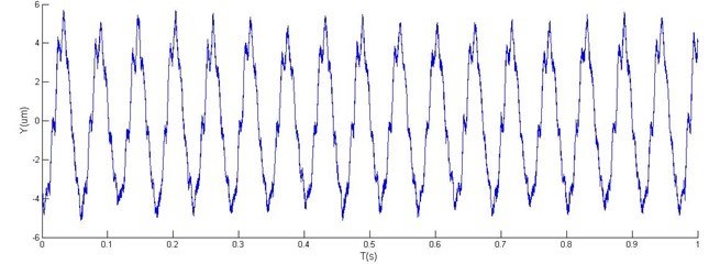
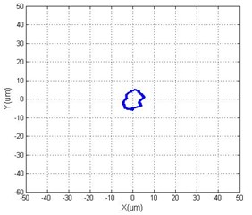
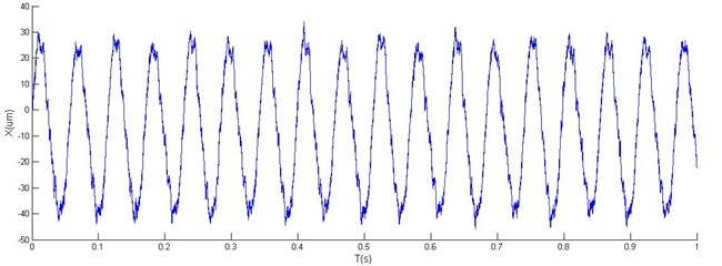
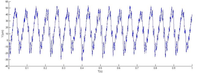
Fig. 8Horizontal, vertical vibration and orbit of rotor with 2 DOF PID controller
a)
b)
c)
Two tests were performed, one for steady-state response, another for acceleration response.
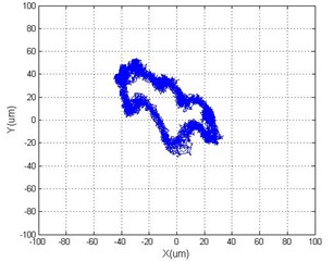
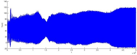
In Fig. 8 and Fig. 9, a comparison of simulation results using the conventional PID (1 DOF) and the 2 DOF PID controllers are shown for both tests. In the control design of the PID controller the static and dynamic limitations caused large overshoot in the time response (Fig. 9). The obtained results show that 2 DOF PID control guarantees higher damping of the closed-loop system and is, therefore, superior to 1 DOF PID control.
As is clear in Figs. 10 and 11, an excellent agreement of experimental results is obtained in the transient state of accelerating response, while the measured position is noticeable in the steady state. An off-set in the measured current is noticeable due to the difference between the geometric and magnetic rotor’s central position. Variations in positions in the -axis are tested in both tests.
Fig. 9Horizontal, vertical vibration and orbit of rotor with 1 DOF PID controller
a)
b)
c)
Fig. 10Accelerating response vertical vibration of rotor with 2 DOF PID controller
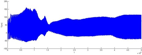
Fig. 11Accelerating response vertical vibration of rotor with 1 DOF PID controller
6. Conclusions
The controller design approach for flexible rotor system with AMB provides a comprehensive for high-speed rotor dynamic systems. Control of 2 DOF was achieved to provide stability and disturbance rejection, even high-speed operation required by the running speed and harmonic-related forces, and with the rotor position feedback sensors and magnetic bearing stator mounted on the flexible housing.
The analytical and experimental results show the effectiveness of the 2 DOF control. Good step responses are achieved as a result of the using 2 DOF PID controller of AMB. With a sufficient bandwidth, robust stability of the designed controllers can be obtained.
Acredible comparison between 2 DOF PID and 1 DOF PID different controllers is possible. From the tested controllers, which can achieve the similar band-width and disturbance rejection, the 2 DOF PID approach shows better robust stability than the 1 DOF PID controller.
The parameters of the AMB system are time-variant. The bending modes of the flexible rotor can shift, for example, because of aging or reassembling of substructures. The 2 DOF PID controller can solve the problem of the conventional PID controller that the optimal tuning for the disturbance response and the one for the set-point response are not compatible in most cases of practical importance. Applying sufficient parameters of and in the 2 DOF PID control design and uncertainty models in the stability analysis are necessary.
It is very important in the AMB of process control where the change of the setpoint variable is frequently required. This article is intended to be a reference for AMB engineers who are faced to the problem. The future work will focus on controller design using high-performance embedded signal processing units, such as DSPs.
References
-
Kasarda M. E. F. An overview of active magnetic bearing technology and applications. Shock and Vibration Digest, Vol. 32, No. 2, 2000, p. 91-99.
-
M. Dussaux. The industrial applications of active magnetic bearing technology. Proceedings of the Second International Symposium of Magnetic Bearings, Tokyo, Japan, 1990, p. 33-38.
-
Kim C., Palazzolo A. B., Kascak A., Beach R. Eddy current effects on the design of rotor-magnetic bearing systems. Transactions of the ASME, Journal of Mechanical Design, Vol. 117, 1995, p. 162-170.
-
Jeong H., Kim C., Lee C. Modeling and control of cone-shaped active magnetic bearing system. Proceedings of the International Symposium on Magnetic Bearings, Vol. 4, Zurich, Switzerland, 1994, p. 23-28.
-
Betschon F., Knospe C. R. Reducing magnetic bearing currents via gain scheduled adaptive control. IEEE/ASME Transactions on Mechatronics, Vol. 6, Issue 4, 2001, p. 437-443.
-
Lum K. Y., Coppola V. T., Bernstein D. S. Adaptive autocentering control for an active magnetic bearing supporting a rotor with unknown mass imbalance. IEEE Trans. Contr. Syst. Technol., Vol. 4, Issue 5, 1996, p. 587-597.
-
Betschon F. Schob. On-line adapted vibration control. Proc. 6th Int. Symp. Magnetic Bearings, Cambridge, MA: Mass. Inst. Technol., 1998, p. 362-371.
-
Hirata M., Nonami K., Ohno T. Robust control of a magnetic bearing system using constantly scaled H-infinity control. Proc. 6th Int. Symp. Magnetic Bearings, Cambridge, MA: Mass. Inst. Technol., 1998, p. 713-722.
-
Kanemitsu Y., Ohsawa M., Marui E. Comparison of control laws for magnetic levitation. Fourth International Symposium on Magnetic Bearings, ETH Zuerich, 1994, p. 13-18.
-
Duan G., Howe R. Robust magnetic bearing control via eigenstructure assignment dynamical compensation. IEEE Trans. Contr. Syst. Technol., Vol. 11, Issue 2, 2003, p. 204-215.
-
Schuhmann T., Hofmann W., Werner R. Improving operational performance of active magnetic bearings using Kalman filter and state feedback control. IEEE Transactions on Industrial Electronics, Vol. 59, Issue 2, 2012, p. 821-829.
-
Steffani H. F., Hofmann W., Cebulski B. A controller for a magnetic bearing using the dynamic programming method of Bellman. Proc. 6th Int. Symp. Magnetic Bearings, Cambridge, MA: Mass. Inst. Technol., 1998, p. 569-576.
-
L. Li. On-line tuning of AMB controllers using genetic algorithms. Proc. 6th Int. Symp. Magnetic Bearings, Cambridge, MA: Mass. Inst. Technol., 1998, p. 372-382.
-
Fan Y. H., Chen K. Y., Tung P. C. Switching-type self-tuning fuzzy PID control of an active magnetic bearing system. Applied Mechanics and Materials, Vol. 284, 2013, p. 2330-2336.
-
Shuliang Lei, Alan Palazzolo, U. Na, A. Kascak. Non-linear fuzzy logic control for forced large motions of spinning shafts. Journal of Sound and Vibration, Vol. 235, Issue 3, 2000, p. 435-449.
-
J. D. Lindlau, C. R. Knospe. Feedback linearization of an active magnetic bearing with voltage control. IEEE Trans. Contr. Syst. Technol., Vol. 10, 2002, p. 21-30.
-
K. Youcef-Toumi, S. Reddy. Dynamic analysis and control of high speed and high precision active magnetic bearings. ASME J. Dyn. Syst., Meas., Contr., Vol. 114, 1992, p. 623-633.
-
T. Mizuno. Analysis on the fundamental properties of active magnetic bearing control systems by a transfer function approach. JSME Int. J. Series C, Mech. Syst. Mach. Elements Manufact., Vol. 44, 2001, p. 367-373.
-
F. Losch, C. Gahler, R. Herzog. μ-synthesis controller design for a 3 MW pump running in AMBs. Proc. 6th Int. Symp. Magnetic Bearings, Cambridge, MA: Mass. Inst. Technol., 1998, p. 415-428.
-
I. M. Horowitz. Synthesis of Feedback Systems. New York, Academic Press, 1963.
-
M. Araki. PID control system with reference feed forward (PID-FF control system). Proc. 23rd SICE (Society of Instrument and Control Engineers) Annual Conference, 1984, p. 31-32.
-
M. Araki.On Two-Degree-of-Freedom PID Control Systems. SICE Research Committee on Modeling and Control Design of Real Systems, 1984.
-
K. Hiroi. Two-degree-of-freedom PID control system and its application. Instrumentation, Vol. 29, 1986, p. 39-43.
-
M. Namie, T. Ueda, T. Tsukabe, H. Taguchi. Two-degree-of-freedom PID controller used for temperature control: simultaneity reference response and disturbance response. OMRON Technics, Vol. 28, 1988, p. 285-291.
-
K. Hiroi, K. Yonezawa. Reference-filter type two-degree-of-freedom PID control system. Proc. 24th SICE Annual Conference, 1985, p. 217-218.
-
H. Taguchi, M. Doi, M. Araki. Optimal parameters of two-degree-of-freedom PID control systems. Trans. SICE, Vol. 23, 1987, p. 889-895.
About this article

This work was supported by the National Natural Science Foundation of China, Project No. 10772160.
