Abstract
The study presents a numerical investigation of the influence of horn geometry on the performance of a 20 kHz ultrasonic testing system used for Very High Cycle Fatigue (VHCF) applications. The system, comprising an aluminium horn and duplex 2205 steel specimen, was evaluated using COMSOL Multiphysics. Four horn geometries – conical, stepped-conical, exponential, and stepped-cylindrical – were analysed to compare their ability to amplify displacement and stress under varying input voltages. Findings indicate the importance of horn geometry in achieving optimal resonance and mechanical amplification, offering valuable insight for the design of efficient ultrasonic fatigue testing systems.
1. Introduction
Very High Cycle Fatigue (VHCF) ultrasonic fatigue testing method allows to examine fatigue life properties of metallic materials in the 20 kHz frequency range. Due to high frequency nature of the method it is possible to perform accelerated and cheaper fatigue evaluation of materials at 107-1010 load cycles which is critical to various industries.
In this study ultrasonic fatigue testing system constant component is the 20 kHz 2000 W ultrasonic transducer which consists of piezoelectric ceramic, stack bolt, aluminium back cover plate and front driver as shown in Figure 1.
Fig. 1Ultrasonic transducer
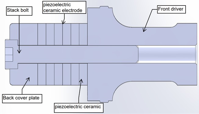
A key component of the ultrasonic testing system is the concentrator (horn), which amplifies displacement and stress from the piezoelectric actuator into the specimen. This study focuses on numerical evaluation of various horn geometries at ~20 kHz excitation using COMSOL Multiphysics to determine which geometry approach offers best amplification and is worth investigating further. To perform the analysis solid mechanics and electrostatics physics are used together with piezoelectricity Multiphysics.
2. Methodology
2.1. Specimen geometry, material and measurement points
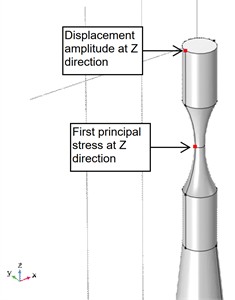
Specimen was designed according to WES 1112: 2017 standard specifications as shown in Fig. 2. To simulate realistic testing conditions duplex 2205 steel was selected as specimen material. Two points of measurement were selected for analysis: one point in the middle of the specimen to evaluate the first principal stress at direction and second point at the tip of the specimen to evaluate the displacement amplitude at direction as shown in Fig. 3.
Fig. 2Specimen geometry
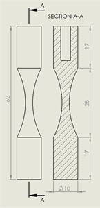
Fig. 3Points of measurement on the specimen
2.2. Horn design and material
For fast and low-cost prototyping and experimental validation in the future research aluminium was selected in this study as horn material due to its low cost, good acoustic properties, good fatigue resistance and excellent machinability.
The horn length was determined on the half-wavelength resonance criteria for longitudinal vibrations in aluminium. Using a typical longitudinal wave speed of 6300 m/s in aluminium and a target frequency of 20 kHz, calculated wavelength is 315 mm. The resulting horn length of 144,2 mm was determined in COMSOL through eigenfrequency analysis to match exact mode shape at ~20 kHz and the resonant system included the 62 mm 2205 steel specimen and was used in all the following simulations.
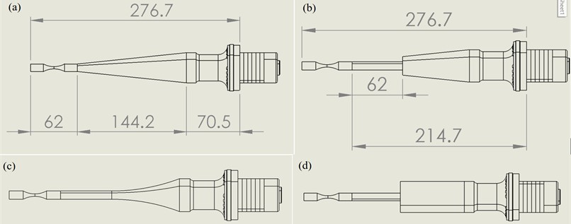
Conical, stepped-conical, exponential and stepped-cylindrical horns were evaluated as illustrated in Fig. 4. The 62 mm step from the specimen in the horn geometry was implemented to investigate its effect on the amplification of displacement and the resulting stress at the specimen.
2.3. Governing equations for ultrasonic fatigue testing modeling
In this study Navier-Cauchy equation of motion describes the mechanical behaviour of solids, accounting for internal stresses and external loads cause material to deform:
where: 𝜎 – stress tensor, – body force vector, 𝜌 – material density, – second time derivative of displacement (acceleration).
Fig. 4Different horn geometries: a) conical, b) stepped-conical, c) exponential, d) stepped-cylindrical
Eigenfrequency analysis is used to determine the natural frequencies (resonances) of the structure:
where: – material density, – angular frequency, – displacement vector, – divergence of the stress tensor.
Frequency domain analysis is used to simulate steady-state harmonic response to time-harmonic excitation:
where: – material density, – angular frequency, – displacement vector, – divergence of the stress tensor, – time-harmonic excitation force vector, with representing phase angle .
The solution for displacement for the first resonance mode relative to wave number and angular frequency :
The strain field varies sinusoidally in space and time and is proportional to the spatial and temporal variations:
3. Results
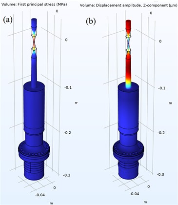
Simulations were performed in COMSOL using solid mechanics, electrostatics and piezoelectricity multiphysics coupling. Eigenfrequency study was performed to identify desired mode shape at frequency close to 20 kHz. Frequency domain study was used to analyse displacement and stress near the resonance for conical (Fig. 5), stepped-conical (Fig. 6), exponential (Fig. 7) and stepped-cylindrical (Fig. 8). “Parametric sweep at 200 V, 400 V, 600 V and 800 V was performed to compare displacement amplitudes and principal stress provided in Table 3.
Fig. 5Conical horn geometry: a) mode shape at displacement amplitude and b) first principal stress
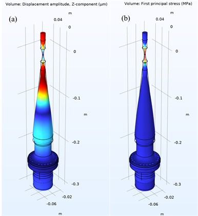
Fig. 6Stepped-conical horn geometry: a) mode shape at displacement amplitude and b) first principal stress
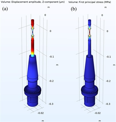
Fig. 7Exponential horn geometry: a) mode shape at displacement amplitude and b) first principal stress
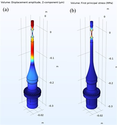
Fig. 8Stepped-cylindrical horn geometry: a) mode shape at displacement amplitude and b) first principal stress
Despite the same length different horn geometries resulted in different resonant frequencies close to 20 kHz at desired mode shape as provided in Table 1. The highest determined frequency was for the conical geometry and the lowest for exponential. The exponential horn requires the most length adjustments while the conical horn requires the least length adjustments to achieve frequency as close as possible to 20 kHz.
Table 1Resonant frequencies for different horn geometries
Conical | Stepped-conical | Exponential | Stepped-cylindrical | |
Resonant frequency, Hz | 20149 | 19700 | 18547 | 19837 |
For all horn types, increasing the voltage leads to higher maximum displacement and stress. This is consistent with the behaviour of piezoelectric transducers where displacement is proportional to input voltage.
Stepped-conical horn provides the best amplification, at 800 V it results in 38.8 µm displacement and 46.3 MPa first principal stress at direction. This indicates that conical to cylindrical step transition helps in the amplification of the vibrational force more efficiently than other geometry approaches. Stepped-cylindrical horn geometry results in the highest displacement 55.9 µm at 800 V. However, the corresponding stress is only 24.7 MPa at 800 V, indicating that most of the energy goes into displacement amplification rather than stress concentration. Conical horn performs moderately compared to other geometry approaches. Exponential horn results in fair balance between stress and displacement.
Stress intensity per unit of displacement ratio for each horn geometry, which determines the efficiency of the geometry, is provided in table 3. Findings indicate that conical geometry is the most stress-efficient, followed by exponential horn geometry. Stepped-conical provides good amplification but results in less stress per µm. Stepped-cylindrical produces the most vibration and is the least efficient at concentrating stresses.
Table 2Horn geometry effects on displacement and first principal stress at different voltages
Horn geometry | Voltage (V) | Maximum displacement (µm) | First principal stress at maximum displacement (MPa) |
Conical | 200 | 2.9 | 7.2 |
400 | 5.8 | 14.4 | |
600 | 8.7 | 21.6 | |
800 | 11.6 | 28.8 | |
Stepped-conical | 200 | 9.7 | 11.6 |
400 | 19.4 | 23.1 | |
600 | 29.1 | 34.7 | |
800 | 38.8 | 46.3 | |
Exponential | 200 | 5.9 | 8.7 |
400 | 11.7 | 17.3 | |
600 | 17.6 | 26 | |
800 | 23.4 | 35 | |
Stepped-cylindrical | 200 | 14 | 6.2 |
400 | 28 | 12.3 | |
600 | 42 | 18.5 | |
800 | 55.9 | 24.7 |
Table 3Stress concentration efficiency for different horn geometries
Conical | Stepped-conical | Exponential | Stepped-cylindrical | |
Stress/displacement MPa/µm ratio | 2.483 | 1.193 | 1.48 | 0.441 |
Findings indicate that the horn geometry and specimen material plays a critical role in the resonant frequency of the system as well as resulting amplitudes and stresses although the length of the system remains unchanged. More problems would arise if a variety of different material specimens would need to be tested. While focusing only on the horn geometry it would result in need of a specific horn geometry for a specific material to be tested. Future research should focus on the most versatile approach in system design while utilising same horn geometry while adjusting the geometry and length of the specimen accordingly to the material to be tested. For that reason stepped-conical and exponential horn geometries seems to be the most promising due to the fact that their diameter after the step matches the specimen diameter.
4. Conclusions
After conducting research, the following conclusions were formulated:
1) The stepped-conical horn achieves the best combination of displacement and stress amplification for high-stress ultrasonic fatigue applications.
2) The stepped-cylindrical horn geometry generates the highest displacement but has the lowest stress concentration efficiency.
3) The conical horn offers the highest stress concentration efficiency, although one geometry is limited to one material to be tested.
4) The exponential horn provides second best stress concentration efficiency with moderate displacement and stress amplification.
5) System length is not the only factor determining system frequency, it is also influenced by the different materials and their geometries of which the system is composed.
References
-
F. K. Fiorentin, “A numerical and experimental study on residual stresses, distortion and fatigue behaviour of additive manufactured components,” INEGI, 2020.
-
F. K. Fiorentin, “High-Cycle and ultra-high cycle fatigue behaviour of directed energy deposited Inconel 625,” University of Porto, 2023.
-
C. Bathias and P. C. Paris, Gigacycle Fatigue in Mechanical Practice. CRC Press, 2004, https://doi.org/10.1201/9780203020609
-
M. Zimmermann, “Very high cycle fatigue,” in Handbook of Mechanics of Materials, Singapore: Springer Singapore, 2017, pp. 1–38, https://doi.org/10.1007/978-981-10-6855-3_43-1
-
“Electric Potential from Electric Field.” Physics Libretexts, 2020. https://phys.libretexts.org/bookshelves/electricity_and_magnetism/book%3a_electricity_and_magnetism_(tatum)/04%3a_potential_and_field_relationships/4.01%3a_electric_potential_from_electric_field.
-
“Piezoelectric Materials: Understanding Standards.” COMSOL Blog, 2014. https://www.comsol.com/blogs/piezoelectric-materials-understanding-standards.
-
“WES 1112:2017 – Standard method for ultrasonic fatigue test in metallic materials,” The Japan Welding Engineering Society, Tokyo, Japan, 2017.
About this article

The authors have not disclosed any funding.
The datasets generated during and/or analyzed during the current study are available from the corresponding author on reasonable request.
The authors declare that they have no conflict of interest.
