Abstract
Accurate monitoring of robotic Tool Centre Point (TCP) trajectories is essential for ensuring precision, repeatability, and quality in industrial processes such as welding, milling, and assembly. The proposed framework integrates computer vision techniques with trajectory analysis to facilitate the monitoring of robotic operations. The system integrates an industrial robot with an HD camera and Python-based OpenCV processing to visualize and evaluate deviations in real time. The methodology is structured into three stages: (i) contour detection and preprocessing of visual data, (ii) trajectory tracking and visualization, and (iii) accuracy evaluation through nearest-neighbor point cloud analysis and Euclidean distance metrics. The findings demonstrate the system's capacity to reliably detect pointer motion, remove irrelevant background information and compute deviations with millimeter-scale precision. A comparative investigation was conducted to determine the accuracy, consistency, and robustness of automated monitoring in comparison to manual observation.
Highlights
- Using this vision-based tool centre point tracking method, industrial robot tool trajectories can be automatically detected and visualized in real time with millimeter-level precision
- Using this cost-effective camera and OpenCV framework, robot performance can be monitored without additional sensors or expensive measurement systems
- Using this nearest-neighbor and Euclidean distance evaluation method, TCP deviations from reference paths can be quantified with an average accuracy of 91.7% compared to manual inspection
1. Introduction
Accurate monitoring of robotic Tool Centre Point (TCP) trajectories is a critical factor in ensuring precision, repeatability, and quality in industrial processes such as welding, milling, and assembly. Current industrial robots are being utilized with increased frequency in applications that demand a high degree of accuracy [1]. For instance, deviations in TCP paths can result in a reduction in product quality, an increase in tool wear, or even safety risks [2]. Consequently, the utilization of robust monitoring tools capable of real-time trajectory visualization and accuracy assessment is essential for advanced manufacturing environments.
According to recent literature, there is an increasing demand for trajectory monitoring solutions. Research has highlighted the importance of computer vision techniques for robotic accuracy evaluation [3], the utilization of deep learning to enhance real-time trajectory tracking, and advanced sensor fusion approaches integrating cameras, LiDAR, and IMUs [4]. Vision-based contour and edge detection has been widely applied for robotic path verification [5], while hybrid approaches combining model-based and data-driven techniques have been shown to improve accuracy and reduce uncertainty [6]. Furthermore, efforts to enhance TCP calibration and error compensation have been documented, with researchers investigating machine learning for adaptive compensation [7], digital twins for robotic monitoring [8], and augmented reality for operator-assisted trajectory validation [9]. Furthermore, studies on adaptive control systems emphasize the importance of accurate trajectory feedback for ensuring smooth dynamic response [10].
This work proposes the framework development of an industrial robot TCP tracker, which integrates computer vision and trajectory analysis methodologies to facilitate the monitoring of robotic operations. The system facilitates real-time cost-effective visualization of pointer motion, comparison with predefined trajectories, and quantitative accuracy evaluation of the framework. The contributions of this study are as follows: (i) the framework development, consisting of contour detection, trajectory visualization, and accuracy assessment; (ii) the implementation is achieved through the integration of industrial robot “Motoman HC10DTP” (Yaskawa, Japan) and HD camera with the Python programming language and OpenCV library, enabling cost-effective deployment; (iii) the validation part covering the use of a system for the comparison of tracked trajectories with ground-truth paths, with the objective of evaluating deviation metrics in millimeters.
2. Workflow of the framework
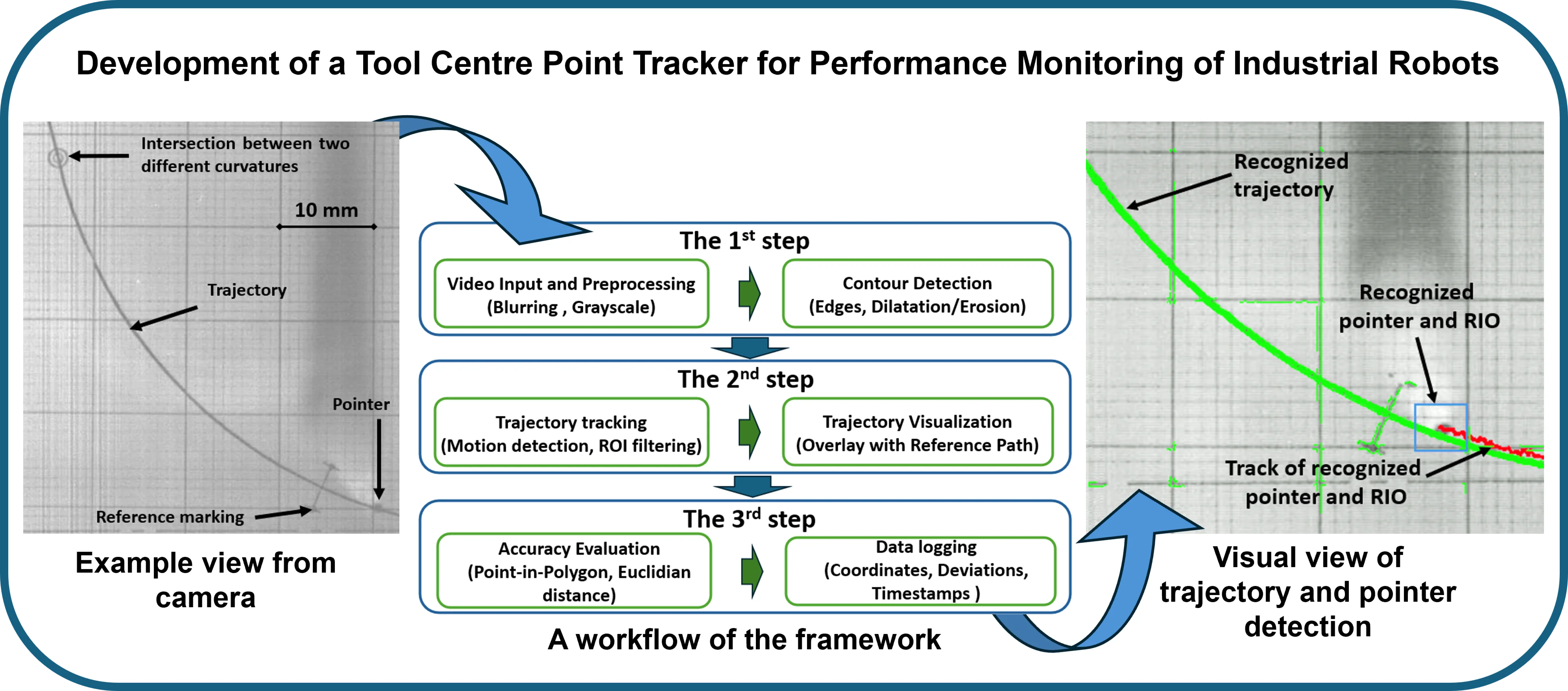
The development of the TCP tracker is based on a three-stage process that integrates computer vision methods with trajectory analysis in a unified workflow. For the hardware, industrial robot “Motoman HC10DTP” (Yaskawa, Japan) with the attached pointer tool and predefined generated trajectories are used for this study (Fig. 1).
Fig. 1Structural representation of the experiments
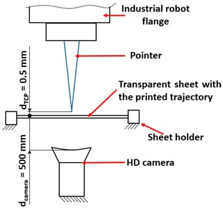
a) Structural schematics of pointer tracking
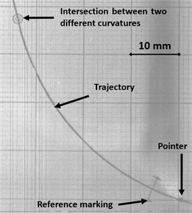
b) Example view from HD camera
To visually evaluate the tracking accuracy of the pointer, the camera is placed under the transparent sheet, on which the predefined trajectories are printed on the millimeter scale square markings for a reference. The initial stage of the process is focused on machine vision-based automatic contour detection and the processing of visual data (Fig. 2).
Fig. 2A workflow of the framework
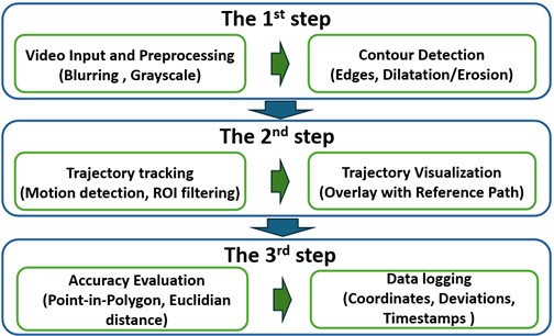
In this context, image frames captured using HD camera from the robotic environment are processed firstly by implementing Gaussian blurring to reduce noise and followed by grayscale conversion to simplify image structures. The edge detection is then performed using the Canny algorithm, which highlights the edges in the image by detecting areas with significant intensity changes. The morphological operations such as dilation (edges thickening to connect disjointed shapes) and erosion (edge shrinking to remove noise) are applied to refine the contour quality. This stage is responsible for the generation of a set of trajectory contours that are characterized by clarity and represent the motion of the tool tip in and coordinates.
The second stage of the framework involves trajectory tracking and visualization. The detection of motion is achieved through the calculation of frame-to-frame differences, thereby highlighting the movement of the TCP. The extraction and filtering of contours process ensure the preservation of motion within the region of interest (ROI). The centers of these contours are computed and linked together to reconstruct the tool trajectory. The reconstructed trajectory is then overlaid on the video data, thereby enabling real-time visualization of the actual TCP path in comparison with the predefined reference trajectory.
The third stage of the workflow addresses accuracy evaluation and deviation measurement. The tool position is determined by comparing each detected TCP point with the predefined trajectory. This is achieved by conducting a point-in-polygon test, the purpose of which is to verify whether the tool position lies inside the expected contour. The quantitative assessment of deviations is achieved by calculating the Euclidean distance between the measured trajectory points and the reference trajectory points according to ISO 9283:1998 standard [11]. This is then converted from pixel units to mm scale with a calibration factor (1 pixel ≈ 0.0095 mm). The deviation values, along with the corresponding timestamps and coordinates, are stored in an Excel database or further evaluation.
3. Results
In order to evaluate the accuracy of the proposed TCP tracker, ten different reference points were selected along predefined robot trajectories for analysis. Each point on the trajectory is represented by a specific location, including straight-line segments, arc midpoints, and random locations. For each reference point, the deviation from the nominal trajectory was measured in two ways. Firstly, the process of manual monitoring involved the inspection of video frames by a human, who then estimated the deviation using scaled overlays. Secondly, the automated monitoring using OpenCV was used to detect the TCP and its coordinates, compared them with the predefined trajectory, and computed deviations using the Euclidean distance method (Fig. 3).
Fig. 3Visual view of trajectory and pointer detection
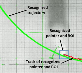
One of the main challenges has been to detect the original trajectory, since it overlaps with reference grid lines, which after some pre-processing is still recognizable by the python library. Therefore, additional thickness filter has been implemented to remove irrelevant recognized lines. For the automatic distance calculation firstly, nearest-neighbor method was implemented to organize the point cloud to smooth centerline with normal. Then, the distance between the pointer and the local normal is calculated to represent the deviation of the pointer. Fig. 4 represents the comparison between manual observation and using OpenCV for pointer deviation monitoring. Colored bars show monitored deviations using two methods. The pink bars show the deviations of the TCP from the reference trajectory that were manually monitored, while the blue bars show the deviations that were automatically detected by the OpenCV-based framework at ten reference points. The green line shows the percentage relative error of the automated detection method compared with manual observation.
Fig. 4Statistical comparison between manual observation and using OpenCV for pointer deviation monitoring
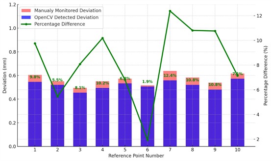
Overall, the developed framework achieved an average recognition accuracy of 91.7 %, which was calculated using all comparisons between manual observation and OpenCV-based pointer deviation monitoring. The designed system has demonstrated its ability to provide decent real-time measurements. As can be seen from the graph, the smallest observed relative error was 1.9 %, while the largest was 12.4 %. These variations are mainly caused by interference from the background grid lines, which are sometimes mistakenly detected as part of the trajectory. These artefacts reduce the clarity of the extracted path and lead to recognition inaccuracies. Nevertheless, the framework shows strong potential for practical use, and further improvements in preprocessing, such as filtering of irrelevant contours and noise reduction, are expected to significantly increase monitoring precision and robustness.
4. Conclusions
The present study set out to develop and evaluate a vision-based TCP tracker for industrial robotic monitoring. The proposed framework successfully integrates computer vision and trajectory analysis into a three-stage workflow consisting of contour detection, trajectory visualization, and quantitative deviation evaluation. The findings demonstrated that the system effectively addresses key challenges, such as background information overlapping, by introducing a thick filter and applying a nearest-neighbor approach to organize trajectory point clouds into smooth centerlines for robust deviation measurement. A series of comparative experiments were conducted, which demonstrated that the automated OpenCV-based method yielded decent levels of average accuracy of 91.7 % compared to manual monitoring. It is evident that the TCP tracker provides a cost-effective, adaptable solution for industrial robotics, although further improvements are required to ensure reliable monitoring.
References
-
P. Bilancia, S. Ferrarini, R. Berni, and M. Pellicciari, “Assessing path accuracy in industrial robots via ballbar technology,” Industrial Robot, Vol. 52, No. 4, pp. 477–490, Sep. 2024.
-
F. Wang, J. Hu, Y. Qin, F. Guo, and M. Jiang, “Trajectory tracking control based on deep reinforcement learning for a robotic manipulator with an input deadzone,” Symmetry, Vol. 17, No. 2, p. 149, Jan. 2025, https://doi.org/10.3390/sym17020149
-
Z. Wu et al., “Visual edge feature detection and guidance under 3D interference: A case study on deep groove edge features for manufacturing robots with 3D vision sensors,” Sensors and Actuators A: Physical, Vol. 381, p. 116082, Jan. 2025, https://doi.org/10.1016/j.sna.2024.116082
-
J. Zhu, H. Li, and T. Zhang, “Camera, LiDAR, and IMU based multi-sensor fusion SLAM: a survey,” Tsinghua Science and Technology, Vol. 29, No. 2, pp. 415–429, Apr. 2024, https://doi.org/10.26599/tst.2023.9010010
-
M. González, A. Rodríguez, U. López-Saratxaga, O. Pereira, and L. N. López de Lacalle, “Adaptive edge finishing process on distorted features through robot-assisted computer vision,” Journal of Manufacturing Systems, Vol. 74, pp. 41–54, Jun. 2024, https://doi.org/10.1016/j.jmsy.2024.02.014
-
J. Wang, Y. Li, R. X. Gao, and F. Zhang, “Hybrid physics-based and data-driven models for smart manufacturing: Modelling, simulation, and explainability,” Journal of Manufacturing Systems, Vol. 63, pp. 381–391, Apr. 2022, https://doi.org/10.1016/j.jmsy.2022.04.004
-
Z. Liu, Q. Liu, W. Xu, L. Wang, and Z. Zhou, “Robot learning towards smart robotic manufacturing: A review,” Robotics and Computer-Integrated Manufacturing, Vol. 77, p. 102360, Oct. 2022, https://doi.org/10.1016/j.rcim.2022.102360
-
Q. Qin et al., “Robot digital twin systems in manufacturing: technologies, applications, trends and challenges,” Robotics and Computer-Integrated Manufacturing, Vol. 97, p. 103103, Feb. 2026, https://doi.org/10.1016/j.rcim.2025.103103
-
E. Hayden, K. Wang, C. Wu, and S. Cao, “Augmented reality procedure assistance system for operator training and simulation,” Proceedings of the Human Factors and Ergonomics Society Annual Meeting, Vol. 64, No. 1, pp. 1176–1180, Feb. 2021, https://doi.org/10.1177/1071181320641281
-
W. Guo and S. Tateno, “Semantic web-driven hybrid adaptive control system for trajectory tracking in robotic arms,” International Journal on Semantic Web and Information Systems, Vol. 21, No. 1, pp. 1–30, Dec. 2024, https://doi.org/10.4018/ijswis.364842
-
“Manipulating industrial robots, Performance criteria and related test methods,” International Organization for Standardization, ISO 9283:1998, 1998.
About this article

The authors have not disclosed any funding.
The datasets generated during and/or analyzed during the current study are available from the corresponding author on reasonable request.
