Abstract
The aim of the work is to determine the parameters of the mathematical model of the motion control system (MCS), which provides automatic monitoring of deep-sea communications with the minimum number of control devices of the MCS, due to which it is possible to use additional monitoring equipment. Mathematical models of the motion of an underwater robot are presented, block diagrams are constructed and the results of the motion of an underwater robot in the vertical and horizontal planes using the Matlab Simulink graphical simulation environment are obtained.
Highlights
- Robot motion control system
- Accuracy of underwater robot maneuvering
- Minimum number of onboard devices
Underwater robots are intended for solving problems of monitoring deep-sea communications. Special equipment on board of the underwater robot can record the status of the pipeline and other deep-water equipment [1].
The underwater robot is a reusable object, and after completing the task, it must return to the carrier to receive a new task or to replenish the consumed resource [2].
1. Controlled motion of the underwater robot in the vertical plane
The first version of the mathematical model uses linear models of sensors to measure the kinematic parameters of the underwater robot. Thus, the mathematical model of controlled motion for underwater robot in vertical plane will be written (Eq. (1)) [3]:
where – angle of attack; – projected angular velocity vector on the axis; – angle of pitch; – depth; – control function of the measured parameters (the value of horizontal rudder angle); – linear velocity; , – parameters of control function; , , , – initial values of the corresponding parameters; , , – set values of the corresponding parameters; – matrix, the elements of which contain information about the geometric, weight and hydrodynamic characteristics of the underwater robot.
The solution of the first four equations of the system allows to obtain information about the parameters of the underwater robot, which can be used in the control functions as measured values. Taking into account the task requirements, the measured value of the projected angular velocity vector on the axis of the robot-fixed coordinate frame and the calculated value of pitch can be used as the measured parameter for controlling the movement of the underwater robot in the vertical plane. The equations of the display of the trajectory of the underwater robot in the vertical plane can be written as (Eq. (2)) [3]:
where is coordinate of surge; , – initial values of the corresponding parameters.
The solution of these equations allows to build a trajectory of the underwater robot in a vertical plane in the starting coordinate frame. This trajectory allows to visually control the result of maneuvering the underwater robot in a vertical plane, as the object's response to the action of the corresponding control.
The task of modeling of the controlled motion of the underwater robot in the vertical plane, taking into account the adopted restrictions on the measured parameters, is solved using the Matlab Simulink.
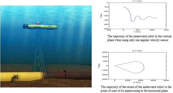
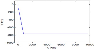
The result of the study of this mode of motion of the underwater robot is shown in Fig. 1. Such a trajectory can be used by an underwater robot when searching for a pipeline in a certain range of depths of robot's possible location.
Fig. 1The trajectory of the underwater robot in the vertical plane when using only one angular velocity sensor
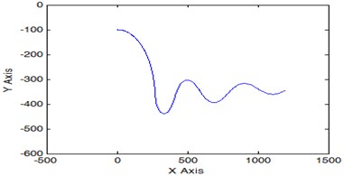
Fig. 2Block diagram for the study of the underwater robot movement in the vertical plane
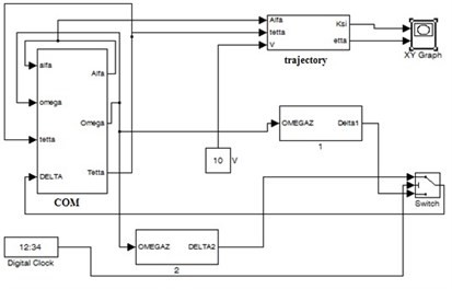
During the study of models of complex structure, it is desirable to allocate it’s functionally complete sections and present them in the form of submodels (see Fig. 2), indicating only input and output variables. This kind of block diagram has the form presented in Fig. 2.
The block COM on this diagram is a representation of structure of control object model for underwater robot and is the source of information about current kinematic parameters of underwater robot. The structure of the model intended for obtaining the trajectory of the underwater robot is shown in the diagram (see Fig. 3) by a block with the identifier such as trajectory. The structure of the model that provides the formation of the control function for the studied mode of underwater robot motion is displayed in Fig. 3 by other blocks, except for COM and trajectory. The mathematical model of the problem of parametric analysis of a motion control system for underwater robot in the vertical plane includes models of measuring instruments of kinematic parameters in explicit form (see Eq. (3)):
where , , – voltage proportional to the measured value; , – an error that shows the scatter of scale factor; , – deadband boundary of the measured pitch; , boundary of the measured value; – maximum voltage proportional to the measured depth.
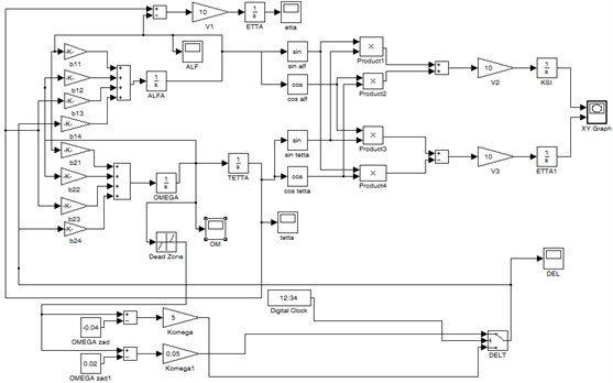
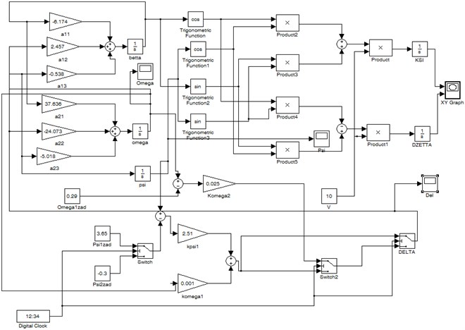
The block diagram of the simulation of the controlled motion of the underwater robot in the vertical plane using the models of measuring instruments of kinematic parameters is shown in Fig. 3.
Fig. 3Block diagram of the simulation of the controlled motion of the underwater robot in the vertical plane using the static characteristics of the measuring instruments of kinematic parameters
The result of modeling of this mode for controlled motion of an underwater robot in the vertical plane is similar to that shown in Fig. 1 and allows us to conclude that the considered maneuvering mode of the underwater robot can be implemented using only one onboard angular velocity sensor of the underwater robot.
To achieve the stabilization of the underwater robot’s depth with this control is not possible, therefore, it was necessary to use the information about the measured value of the current depth, as well as data about the calculated value of the pitch of an underwater robot.
Solving the problem of simulating of controlled motion for underwater robot in a vertical plane using the considered model and a depth sensor made it possible to achieve the required characteristics of a controlled motion for monitoring underwater pipelines.
The trajectory of the underwater robot in a vertical plane using the adopted control functions is shown in Fig. 4.
Fig. 4The trajectory of the underwater robot in depth
Three types of control functions (, ,) are used for the implementation of the three modes of movement of the underwater robot (Eq. (4)):
where – the maximum value of control function.
2. Controlled motion of the underwater robot in the horizontal plane
The model of controlled motion of an underwater robot in the horizontal plane can be described as (Eq. (5)):
where – projected angular velocity vector on the axis; – the drift angle; – the coordinate of sway; – the yaw; – control function of the measured parameters (the value of vertical rudder angle); – common view of control function; – matrix described the control object.
The solution of this system of differential equations can be obtained using a model whose block diagram is shown in Fig. 5.
Fig. 5Block diagram of the simulation of the controlled motion of the underwater robot in the horizontal plane
3. Results
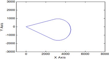
Fig. 6 shows the trajectory of the underwater robot's return to the point where the trajectory of its maneuvering in the horizontal plane was specified when using the model with ideal sensors of kinematic parameters.
Fig. 6The trajectory of the return of the underwater robot to the point of start of its maneuvering in the horizontal plane
4. Conclusions
The use in the control function of only one measured value of the angular velocity allows the underwater robot to conduct a search trajectory of the pipeline in a possible range of depths of its location [4].
The problem of stabilizing the working depth of the underwater motion is solved using a depth sensor, and the movement to the specified depth is carried out using the calculated value of the pitch of underwater robot [5].
For the underwater robot movement along a closed trajectory in the horizontal plane after it performs a given maneuver, the parameters recorded during the initial movement are used, which characterize the stabilized values of the yaw and the angular velocity of underwater robot, as well as the stabilization time of these parameters.
Adding in the study model the static characteristics of the underwater robot sensors made it possible to work out the initial requirements for the sensors of its motion control system, ensuring the required accuracy of maneuvering the underwater robot in the horizontal and vertical planes.
Thus, the possibility of using a minimum number of onboard devices of an underwater robot to ensure its controlled movement and, due to this, an increase in the equipment for quality monitoring of pipelines, is justified.
References
-
Inzartsev A., Pavin A. AUV Application for Inspection of Underwater Communications. In-Tech Publishers, Vienna, 2009, p. 215-234.
-
Ikonnikova I. Self-Propelled Uninhabited Underwater. Publishing House Shipbuilding, Leningrad, 1986,263p.
-
Zhukov Yu Computer Simulation of Marine Automatic Motion Aids. Publishing House SPbGMTU, Saint-Petersburg, 2013, 167 p.
-
Ageev M., Kiselev L., Matvienko Yu Autonomous Underwater Robots: Systems and Technology. Nauka, Moscow, 2005, p. 398.
-
Bobkov V., Morozov M., Bagnitsky A., Inzartsev A., Pavin A., Scherbatyuk A., Tufanov I. Imitation modeling complex for the examination autonomous underwater robot. Scientific Visualization, Vol. 5, Issue 4, 2013, p. 47-70.
About this article

The results were obtained in the framework of the state task of the Ministry of Education of the Russian Federation number 2.5464.2017/Basic Tasks.
