Abstract
Compared with other underwater exploration robots, Spherical underwater robot has an outstanding advantage for the underwater exploration, whose spherical shell has the excellent resiliency to protect the internal electronic components. In addition, this steering resistance is very small to move flexibly. In this paper, a type of spherical underwater robot with the pendulums and a propeller was studied on moving at the water bottom in a rolling manner. The structure and force were analyzed to understand that the hydrodynamic force’s affection on the robot’s rolling at the water bottom. A mathematical model was established with the mass parameters and speeding parameters. The virtual simulation environment was established in Adams software. Furthermore, the coupling fluctuation characteristics of the speed, swing angle and the torque were studied by the simulation and the experiment in a pool. The study proved that this robot not only can use the propeller to move in water, but also can roll at the water bottom by driving the spherical shell. Especially, the result also can be obtained that the robot can roll at water bottom stably by increasing the pendulum mass and lowering the motor speed.
1. Introduction
In recent years, AUV has got much attention in many fields and attracted more and more researchers [1-3]. And, movement flexibility and environmental compatibility are important indicators for an underwater exploration robot [4-6]. Compared with other types of robots, Spherical robot has great advantages in the movement flexibility and environmental compatibility [7-12]. The symmetrical spherical shell can withstand greater pressure and reduce the steering resistance. A kind of underwater spherical robot was developed, ODIN (1991), which is equipped with eight propellers, and every two propellers are assigned together as a group, which can make ODIN move flexibly in a task [13-15]. An underwater spherical robot was developed, URIS (2003), which was equipped with four external propellers [16]. In 2012, a new type of spherical robot was developed with three jetting-water devices and six servo motors, which can change the directions of jetting water [17-19]. And the movement analysis in water was deeply studied for these spherical underwater robots. But these robots did not have the movement ability in the water bottom. So, when the robot moved through underwater propeller, the disturbance from the propeller would affect the collection of samples. Hanxu Sun et al. (2008) designed a spherical robot with heavy pendulum, which can achieve the flexible movement on land [20, 21]. In 2010, a new underwater robot BYSQ-2 was developed with a single propeller [22, 23]. Yansheng Li et al. (2014) studied the hydrodynamic forces and underwater fluctuation characteristics of BYSQ-2 robot [24]. But the features of rolling in the bottom are not fully understood and mastered. So, the analysis for the rolling characteristics is very necessary to improve the underwater environment adaptability. This paper showed the rolling fluctuation characteristics for the sphere robot to expand its movement stability.
This article is organized as follows. In Section 2, the physical model for the robot is introduced, which can move in water by a propeller or in water bottom by rolling. In Section 3, the dynamic equation of rolling is established by Newton Euler method. It is found that the mass and the motor speed are the important parameters for the stably rolling of the underwater robot. In Section 4, the characteristics and influencing factors of coupling fluctuation are analyzed and summarized by building a virtual environment in ADAMS software. In Section 5, an experiment was carried out to demonstrate the ability of stable rolling for the spherical underwater robot. Section 6 provides the conclusions, along with some remarks on future research.
2. Structure and equivalent model
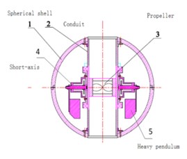
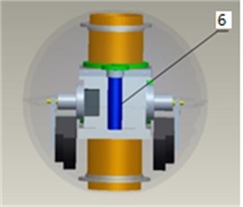
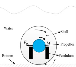
One propeller is designed in the conduit of BYSQ-2 robot, which can provide the thrust for moving in water. And the pendulums locate in both sides of the conduit, which are protected by the spherical shell of the robot. And the conduit is fixed with the spherical shell, which is perpendicular to the short axis. Both the conduit and spherical shell can not only rotate around the long axis, but also rotate around the short axis. So, the robot can roll freely at the water bottom by the motor driving the pendulums. The electronic components are all installed in the spherical glass fiber shell. The main structures of the robot include the spherical shell 1, the conduit 2, the propeller 3, the short axis 4, the pendulum 5 and the rolling motor 6. The physical structure is shown in Fig. 1(a), 1(b). The simplified diagram of rolling at the water bottom is shown in Fig. 1(c).
Fig. 1Model of the robot’s structure and driving forces
a)
b)
c)
According to the conditions of the actual environment and physical structure, two assumptions are made to analyze the rolling characteristics at the water bottom and establish the dynamic model of the robot. Firstly, spherical robot system is simplified to the weight section and the spherical shell portion. The qualities of the components what are fixed with the heavy pendulum mechanism together are concentrated equivalently in the center of the pendulum. And the qualities of the components what fixed on the spherical shell together are concentrated equivalently in the center of the spherical shell. Secondly, according to the symmetrical design, the rotational inertia’s spindle of the spherical shell that includes the structures fixed with the spherical shell goes through the center of the spherical robot.
3. Establish dynamic equations
Spherical robot rolls at the water bottom and its water resistance is not negligible. Because of the buoyancy’s effect, the supportive force between the robot and the water bottom will be reduced. Furthermore, when the robot rolls at the water bottom, the friction will be also reduced between the spherical shell and the bottom. To determine the effect parameters, a model must be firstly established to describe the dynamics of the spherical robot. In the rolling state at the bottom, as the research object, the force diagram of the spherical shell is shown in Fig. 2.
As shown in Fig. 2, the spherical robot is rolling at the water bottom. At the contact point between the spherical shell at the bottom, there are a friction force and a supportive force , which are a pair of interactive forces. Furthermore, the water resistance force and the buoyancy are applied to the spherical shell, which are produced by the water. The horizontal force , the vertical force and the rotational torque are also applied to the spherical shell portion of the robot, which are produced by the internal pendulum mechanism. And, the spherical shell structure itself is also affected by gravity . The parameter is the maximum radius of the robot. And, the parameter is the rolling angular velocity of the robot. The parameter is the mass of the robot. The parameter is the additional mass factor of the robot. The parameter is the velocity of the robot. The parameter is the moment of inertia of the spherical shell. According to Newton Euler’s theorem, the dynamic equations of the spherical shell rolling at the water bottom can be obtained as shown in Eq. (1):
Similarly, in addition to part of a spherical shell, the internal pendulum mechanism should be also analyzed in order to obtain a complete dynamic system equations of the robot. The coordinate origin of the rotating reference system is set in the center of the sphere spherical robot. In order to removal the influences of the Coriolis force, the rotating axis of the heavy pendulum is also set in the center of the sphere spherical robot. The force diagram of the pendulum is shown in Fig. 3.
Fig. 2Force diagrams of the spherical shell rolling at the water bottom
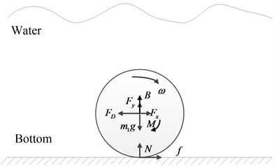
Fig. 3Force diagrams of the internal pendulum mechanism
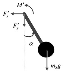
As shown in Fig. 3, driven by a motor, the pendulum swings forward, when the robot rolls forward at the water bottom. The horizontal force , the vertical force and the rotational torque are applied to the internal pendulum mechanism portion of the robot, which are produced by the spherical shell. And, the pendulum structure itself is also affected by gravity. The parameter is the mass of the pendulum. The parameter is the length of the pendulum. And, the parameter is the swing angle of the pendulum. According to Newton Euler’s theorem, the dynamic equations of the pendulum swing can be obtained as shown in Eq. (2):
In Eqs. (1) and (2), the horizontal and , the vertical force and , the rotation moment and , are the paired interaction forces. According to Newton’s third law, these three pairs of forces respectively are equal in size and opposite in direction. According to Eq. (1) and (2), the complete dynamic equations of the robot rolling at the water bottom can be obtained as shown in Eq. (3):
It is supposed that the balancing mass is the extra mass to ensure that the gravity of the robot is greater than the buoyancy of the water, when the spherical robot is rolling at the water bottom. The balancing mass together with the frictional force can be expressed as Eq. (4):
According to Eqs. (3) and (4), the complete dynamic equations with the parameter of the robot rolling at the water bottom can be obtained as shown in Eq. (5):
When the spherical robot is rolling at the water bottom, the swing of the pendulum is driven by a torque of the pendulum motor, whose reaction torque can drive the spherical shell to roll forward. In fact, the rolling angular velocity of the robot is related to the rotational angle of the motor and the swing angle of the pendulum. So, their constraint relationship can be obtained as shown in Eq. (6):
According to Eq. (5) and (6), the complete dynamic equations of the robot rolling at the water bottom also can be obtained as shown in Eq. (7):
As shown in Eq. (7): The rolling state of the spherical underwater robot not only relates to the motor rotational angle , but also relates to the balancing mass of the robot.
4. Simulation model and analysis
In order to analyze the impact of the rotation angle and the balancing mass , the ADAMS prototype and virtual environment were built to research the rolling state of the robot at the water bottom under the conditions of the variable parameters. As assumed in Section 2, two portions are made to analyze the rolling characteristics at the water bottom and establish the dynamic model of the robot. Furthermore, the hydrodynamic coefficients are calculated in FLUENT software and the result is imported into ADAMS software as the simulation constraint conditions. Based on the above principles, the virtual simulation model of the robot rolling at the water bottom is shown in Fig. 4.
Fig. 4Virtual simulation model diagram of the robot rolling at the water bottom
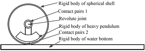
In the virtual simulation environment, a large flat-panel was established as the water bottom, which was set to the fixed rigid body property. The quivalent spherical shell and the equivalent heavy pendulum were also set to the rigid body property and a revolute joint was disposed between the heavy pendulum and spherical shell. This contact pairs were disposed between the two rigid bodies of the spherical shell and the water bottom. Because of the perfect symmetry of the spherical robot, the buoyancy, gravity and hydrodynamics can be applied in the center of the spherical robot. According to the prototype model, the spherical shell diameter was 400 mm. The water density was set to 1000 kg/m3. The gravitational acceleration g was set to 10 m/s2, the buoyancy was set to 354 N. The hydrodynamic parameter was associated with the speed and acceleration parameters of the robot, which also can be disposed on the center of the robot. According to the calculation results in FLUENT software, the drag coefficient associated with quadratic speed items was set to 40 and the drag coefficient associated with the acceleration for additional mass factor is set to 32. is a horizontal composition of force in the opposite direction of the robot movement. is a vertical composition of force in the same direction of gravity. and can be set in the center of the spherical robot, which can be expressed as Eq. (8):
Based on the above spherical robot virtual prototype, this balancing mass of the spherical robot was set respectively at 10 kg and –10 kg. In order to study the influence of the parameter, the motor rotating speed remained consistent and the rolling state of the robot at the water bottom was simulated under the conditions of the different parameters.
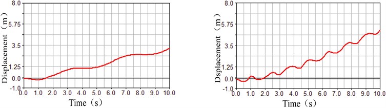
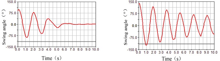
As shown in Fig. 5, the parameter was –10 kg in the left half of the comparison chart. And, the parameter was +10 kg in the right half of the comparison chart. At the same time, the motor rotating speed remained constant. In these conditions, the fluctuation characteristics of the rolling displacement, the swing angle and the motor torque were simulated, where the differences can be seen that the balancing mass greatly affected the fluctuation of the rolling process at the water bottom. As shown in Fig. 5(a), the rolling displacement of the spherical robot at the water bottom increased with the balancing mass increasing in the same time period. This displacement increased from 4 m to 6 m in the comparison chart of the rolling displacement. As shown in Fig. 5(b), the swing angle of the heavy pendulum at the water bottom attenuated quickly with the balancing mass increasing. The swing angle of the heavy pendulum converge to 0 in the 5 s in the condition of the balancing mass +10 kg in the right half of the comparison chart. As shown in Figure 5 (c), the fluctuation of the motor torque discreased obviously with the balancing mass increasing. Based on the above analysis, the conclusion can be drawn that a larger balance mass can increase the stability of the robot rolling at the water bottom.
Furthermore, the balancing mass remained constant and the motor rotating speed is different. The motor rotating speed of the spherical robot was set respectively at 0.5 rad/s and 1.5 rad/s. In order to study the influence of the parameter, the rolling state of the robot at the water bottom was simulated in the condithions of the different parameters.
Fig. 5Fluctuation influence on the rolling state under the different Δm parameters
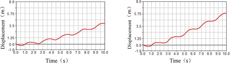
a) Comparison chart of the rolling displacement
b) Comparison chart of the swing angle
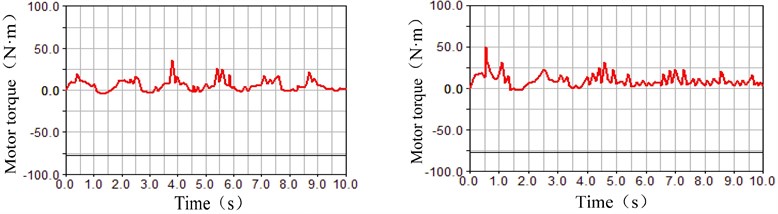
c) Comparison chart of the motor torque
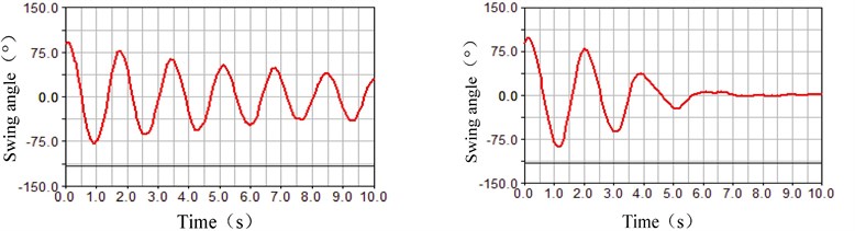
As shown in Fig. 6, the parameter was 0.5 rad/s in the left half of the comparison chart. And, the parameter was 1.5 rad/s in the right half of the comparison chart. At the same time, the balancing mass remained constant. In these conditions, the fluctuation characteristics of the rolling displacement, the swing angle and the motor torque were simulated, where the differences can be seen that the motor rotating speed greatly affected the fluctuation of the rolling process at the water bottom. As shown in Fig. 6(a), the rolling displacement of the spherical robot at the water bottom increased with the motor rotating speed increasing in the same time period. But the relationship was not proportional. As shown in Fig. 6(b), the swing angle of the heavy pendulum at the water bottom did not attenuated quickly with the motor rotating speed increasing. And, the fluctuation became obvious in the 10 s in the condition of the motor rotating speed 1.5 rad/s in the right half of the comparison chart. As shown in Fig. 6(c), the fluctuation of the motor torque became larger than twice with the motor rotating speed increasing. More simulation data was shown in Table 1.
As shown in Table 1, the fluctuation amplitude of the swing angle is maximal and reaches 1.6 rad in the conditions of the total mass 34.1 kg and the motor speed 3 rad. The fluctuation amplitude of the swing angle is minimal and reaches 0.6 rad in the conditions of the total mass 40.2 kg and the motor speed 1.7 rad. Based on the above analysis in Fig. 5, Fig. 6 and Table 1, the conclusion can be drawn that a smaller motor rotating speed can increase the stability of the robot rolling at the water bottom. But, a smaller motor rotating speed can also reduce the moving speed of the robot by the rolling manner at the water bottom.
Table 1Simulation data of the robot rolling at the pool bottom
Total mass (kg) | Motor speed (rad/s) | Amplitude of swing angle (rad) | Time through 3 m (s) |
34.1 | 1.7 | 0.9 | 7.1 |
34.1 | 2.3 | 1.4 | 6.5 |
34.1 | 3 | 1.6 | 6.0 |
37.5 | 1.7 | 0.8 | 7.0 |
37.5 | 2.3 | 1.2 | 6.2 |
37.5 | 3 | 1.4 | 5.7 |
40.2 | 1.7 | 0.6 | 6.4 |
40.2 | 2.3 | 0.9 | 5.5 |
40.2 | 3 | 1.1 | 5.0 |
Fig. 6Fluctuation influence on the rolling state under the different ω parameters
a) Comparison chart of the rolling displacement
b) Comparison chart of the swing angle
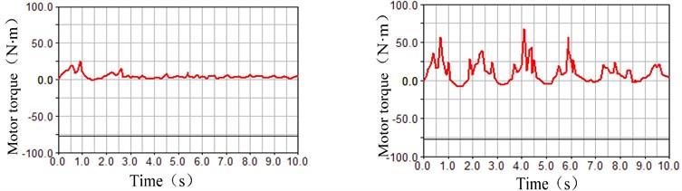
c) Comparison chart of the motor torque
In order to control the motion of spherical robot in the water, Xiaojuan Lan et al (2010) used a fuzzy PID method to suppress the fluctuations of the pendulum, but this method changed the speed value of the motion [23]. Hanxu Sun et al (2014) used a neural network and sliding mode method to control the pitch of the spherical robot, but the neural network initially took lots of time to learn [25]. In this paper, the spherical robot would roll at the water bottom and a direct two-layer sliding surfaces is proposed to control the rolling speed, which is different from the above environment and method in water. Under the rolling condition, the motion equation contains both the rolling constraint and the hydrodynamic constraint, so the governing equations of motion at the water bottom are novel. In the absence of sliding condition, and in a low-speed condition, . According to Eqs. (1), (2) and (3), the equation of motion for the rolling velocity at the water bottom can be obtained as shown in Eq. (9):
The error of rolling velocity is , the two primary sliding surfaces and the ultimate sliding surface are designed as follows:
The derivation of the ultimate sliding surface is shown as follows:
In order to ensure the ultimate sliding surface converging, the control rate is taken as:
In order to make the robot system moves along a sliding surface, the additional switching control must be added, so the total control rate includes the following two components:
The goal of designing controller is to control the rolling velocity, while the swing angle of heavy pendulum is as small as possible. LYAPUNOV function is used to prove the ultimate sliding surface is the stability:
Because is bounded and :
is bounded and asymptotic convergence, and two sliding surfaces are built:
The difference between the two sliding surfaces is integrated:
According to BARBALAT theorem, , the sum between the two sliding surfaces is integrated:
According to BARBALAT theorem, , and in a similar way, . The two primary sliding surfaces and the ultimate sliding surfaces are asymptotic convergence, so the designed controller is stable, which can realize the rolling at the water bottom for the robot stably.
5. Rolling experiment at the water bottom
In this paper, a kind of spherical robot was studied mainly to collect the underwater information. And there was an advantage that the robot can move at the water bottom in a rolling manner, compared with other underwater robots. In this section, it would be proved that the studied spherical underwater robots have the ability to roll at the water bottom through the rolling experiment as shown in Fig. 7.
Fig. 7Experimental picture of the robot rolling at the pool bottom
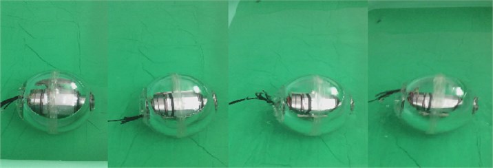
The motor rotational angle and the balancing mass of the robot would affect the rolling state of the spherical underwater robot as shown in Table 1. A pool of length 3 m, width 2 m and height 0.5 m was used as the experimental test site for the spherical underwater robot. During the rolling experiment, the recorded data included the robot’s motor speed , the robot's moving displacement , the robot’s moving time and the robot’s total mass . In each group of experimental parameters, the experiment was made 5 times to get the robot’s moving data. And the average value was recorded. The rolling experiment of the underwater robot was photographed as shown in Fig. 7. The rolling test data of the underwater robot was recorded as shown in Table 2.
Table 2Experimental data of the robot rolling at the pool bottom
Total mass (kg) | Motor speed (r/min) | Moving displacement (m) | Moving time (s) |
34.1 | 50 | 3 | 7.6 |
34.1 | 70 | 3 | 6.8 |
34.1 | 90 | 3 | 6.1 |
37.5 | 50 | 3 | 7.2 |
37.5 | 70 | 3 | 6.6 |
37.5 | 90 | 3 | 5.8 |
40.2 | 50 | 3 | 6.5 |
40.2 | 70 | 3 | 5.8 |
40.2 | 90 | 3 | 5.2 |
According to the rol1ing experimental of the underwater robot in Table 2, in the conditions of the mass 34.1 kg and the motor rotating speed 50 r/min, the rolling speed of the robot was Minimal. Conversely, with the total mass and the motor rotating speed of the robot increasing, the rolling speed also increased. In the conditions of the mass 40.2 kg and the motor rotating speed 90 r/min, the maximum rolling speed can reach 0.6 m/s. However, in the conditions of the greater motor rotating speed, the rolling speed of the underwater robot increased slowly with the total mass increasing rapidly. Even the sliding phenomenon of the robot occured at the water bottom. And the rolling speed was difficult to reach more than 0.6 m/s. The , , and parameters in Eq. (3) was related to the size of the structure of the robot and remained constant. It can be obtained that the water resistance term and the friction term becomed large with the robot rolling speed v increasing. When the friction force reached a maximum, the robot started to slip at the water bottom. The relative sliding between the spherical shell and the water bottom make the robot rolling speed remain unchanged. On the other hand, the heavy pendulum swing inside the robot would affect the bottom's supportive force in the vertical direction, which would change the friction term and cause the fluctuations of the robot rolling at the water bottom in the horizontal direction.
6. Conclusions
As a kind of underactuated spherical underwater robot, it not only can use the propeller to move in the water, but also can drive the spherical shell to roll at the water bottom. The robot can move flexibly and stably, which is beneficial to a long-term observation at the water bottom. This paper researched the fluctuation characteristics of the robot moving in a rolling manner. Firstly, two important influencing parameters was proposed by building a mathematical model of the spherical robot rolling at the water bottom. Secondly, on the basis of building a virtual prototype simulation model, the fluctuation features of the spherical robot rolling at the bottom were analyzed and summarized in the conditions of the different parameters of the balancing mass and the motor rotating speed. Finally, the rolling experiments were carried. And the results showed that the underwater robot had a stable and excellent rolling ability at the water bottom. At the same time,the maximum rolling speed was also obtained.
Several main conclusions can be drawn as follows according to the above analysis of the simulation and experiment.
• The balance mass and the motor rotating speed is the critical parameters to affect the fluctuations of the robot rolling at the water bottom based on the established mathematical model.
• Increasing the balancing mass and reducing the motor rotating speed can suppress the fluctuations of the robot rolling at the water bottom based on the virtual simulation in ADAMS software.
• The robot can roll stably at the water bottom, whose maximum rolling speed is associated with the friction force of the water bottom based on the rolling experiment.
According to the above conclusions, it is necessary to increase the robot’s total mass to reduce the coupling fluctuation and improve the stability of the robot. And it is also important to lower reasonably the motor rotating speed for suppressing the fluctuations, although this is not a good idea. So, a motor rotating controller of the robot will be designed to suppress the rolling fluctuation and improve the rolling speed at the water bottom in future.
References
-
The Navy Unmanned Undersea Vehicle (UUV) Master Plan. U.S. Department of the Navy, 2004.
-
Houston S., Pkwy S. Remotely Operated Vehicles of the World – 9th Edition. Oilfield Publications Limited, USA, 2000.
-
Storkersen N., Kristensen J., Indreeide A., Seim J., Glancy T. Hugin-UUV for seabed surveying. Sea Technology, Vol. 39, Issue 2, 1998, p. 99-104.
-
Naylies I. The Sensory Requirement of a PC Controlled AUV. Master’s Thesis, Offshore Technology Centre, Cranfield University, 2000.
-
Bachmayer R., Leonard N. E., Graver J., Fiorelli E., BhaRa E., Paley D. Underwater gliders: recent developments and future applications. Proceedings of International Symposium on Underwater Technology, Taipei Taiwan, 2004, p. 195-200.
-
Jason E., Meyer N. Dynamics modeling and performance evaluation of an autonomous underwater vehicle. Ocean Engineering, Vol. 31, Issues 14-15, 2004, p. 1835-1858.
-
Shu-xin W., Xiu-jun S., Yan-hui W., Jian-guo W., Xiao-ming W. Dynamic modeling and motion simulation for a winged hybrid-driven underwater glider. China Ocean Engineering, Vol. 1, Issue 25, 2011, p. 97-112.
-
Watson Simon A., Crutchley Dominic J. P., Green Peter N. The design and technical challenges of a micro-autonomous underwater vehicle (μAUV)*. Proceedings of the IEEE International Conference on Mechatronics and Automation, Beijing, China, 2011, p. 567-572.
-
Watson Simon A., Green Peter N. A de-coupled vertical controller for micro-autonomous underwater vehicles (μAUV)*. Proceedings of the IEEE International Conference on Mechatronics and Automation, Beijing, China, 2011, p. 561-566.
-
Yue C., Guo S., Shi L. Hydrodynamic analysis of the spherical underwater robot SUR-II. International Journal of Advanced Robotic Systems, Vol. 10, Issue 3, 2013, p. 119-134.
-
Pan S., Shi L., Guo S. A Kinect-based real-time compressive tracking prototype system for amphibious spherical robots. Sensors, Vol. 15, Issue 4, 2015, p. 8232-8252.
-
He Y., Shi L., Guo S., et al. Preliminary mechanical analysis of an improved amphibious spherical father robot. Microsystem Technologies, Vol. 99, Issue 6, 2015, p. 1-16.
-
Choi H. T., Hanai A., Choi S. K., Yuh J. Development of an underwater robot, ODIN-III. IEEE International Conference on Intelligent Robots and Systems, 2003, p. 836-841.
-
Do K. D., Jiang Z. P., Pan J., Nijmeijer H. Global output feedback universal controller for stabilization and tracking of underactuated ODIN-an underwater vehicle. Proceedings of the IEEE Conference on Decision and Control, 2002, p. 504-509.
-
Antonelli G., Chiaverini S., Sarkar N., West M. Adaptive control of an autonomous underwater vehicle: experimental results on ODIN. IEEE Transactions on Control Systems Technology, Vol. 9, Issue 5, 2001, p. 756-765.
-
Perez Marc Carreras A Proposal of a Behavior-Based Control Architecture with Reinforcement Learning for an Autonomous Underwater Robot. Ph.D. Dissertation, University of Girona, 2008, p. 47-60.
-
Guo S., Lin X., Tanaka K., Hata S. Modeling of water-jet propeller for underwater vehicles Proceedings of the 2010 IEEE International Conference on Automation and Logistics, 2010, p. 92-97.
-
Guo S., Lin X., Tanaka K., Hata S. Development and control of a vectored water-jet based spherical underwater vehicle. Proceedings of the 2010 IEEE International Conference on Information and Automation, 2010, p. 1341-1346.
-
Xichuan L., Shuxiang G. Development of a spherical underwater robot equipped with multiple vectored water-jet-based thrusters. Journal of Intelligent and Robotic Systems, Vol. 67, 2012, p. 307-321.
-
Yili Z., Hanxu S., Qingxuan J., et al. An omni-directional rolling spherical robot with telescopic manipulator. 2nd International Symposium on Systems and Control in Aerospace and Astronautics, ISSCAA, 2008, p. 1-6.
-
Hou Kang, Sun Hanxu, Jia Qingxuan, et al. Structure design and experiment of a spherical aerial vehicle BYFQ-2. 3rd International Conference on Advanced Materials and Information Technology Processing, AMITP, 2013, p. 519-526.
-
L. Xiaojuan, Hanxu S., Qingxuan J. The hydrodynamic analysis for the underwater robot with a spherical hull. Proceedings of SPIE, The International Society for Optical Engineering, Space Exploration Technologies II, Orlando, USA, 2009, p. 73310E.
-
Xiaojuan L., Hanxu S., Qingxuan J. Principle and dynamic analysis of a new-type spherical underwater vehicle. Journal of Beijing University of Posts and Telecommunications, Vol. 33, Issue 3, 2010, p. 20-23, (in Chinese).
-
Li Yansheng, Sun Hanxu, Zhang Yanheng, Chu Ming, Jia Qingxuan, Lan Xiaojuan Characteristic analysis and fluctuation control for a underactuated spherical underwater robot. Journal of Vibroengineering, Vol. 16, Issue 1, 2014, p. 42-56.
About this article

The authors would like to thank the support of China National Natural Science Foundation (51175048) for the research.
