Abstract
The full-discretization method introduced by Ding has high computational efficiency without loss of any numerical precision regardless of low and high radial depth of cut for the stability analysis of ordinary milling operation in time domain. Contrast to ordinary milling, it exists the separation phenomenon between each cutter tooth and the workpiece in feed ultrasonic milling operation. So before analyzing the system stability by the full-discretization method, the contact state between the cutter tooth and the workpiece should be made clear. In this paper, the trajectory method is proposed by the authors to judge the contact state between the cutter tooth and the workpiece. The stability analysis is developed for separated feed ultrasonic and ordinary end milling operations by the above methods and is validated via time domain simulations and experiments for both operations. The analyses show excellent agreement with both the time domain simulations and the experiments. Further, several end milling experiments were conducted that demonstrate the result ultrasonic vibration in feed direction can suppress chatter in machining operations.
1. Introduction
High speed milling technology with high production efficiency, high machining accuracy, high machining surface quality and low cost advantages, has gradually become the mainstream of machining technology, widely used in aviation, aerospace, mold, automotive and other fields [1].
However, in traditional machining technology the cutting vibration displacements between the last time and this time have produced phase difference, thus resulting in the occurrence of machining chatter. The chatter reduces the surface machining accuracy, increases tool wear, and shortens the life of the spindle and so on. So, it is one of the main factors of influencing the system stability. Therefore, it is particularly important to research the problem of machining chatter.
Now there are lots of chatter control methods of which basically have ultrasonic machining method, variable speed cutting method, changing tool geometric angles method and active control laws, intelligent control and so on [2]. Ultrasonic machining method is a technology of combination ultrasonic machining with traditional cutting way. It can improve the traditional cutting machining performance. In recent years, scholars have researched into ultrasonic turning technology and ultrasonic grinding technology deeply and widely. Because the trajectory of milling cutter tooth relative to the workpiece is very complex, the study on ultrasonic vibration assisted milling is little and less on stability problems of ultrasonic vibration assisted milling.
Separated feed ultrasonic milling is continuous separation system between the cutter tooth and the part because of applying ultrasonic vibration in feed direction at low radial depth of cut. For stability analysis of milling system at low radial depth, the scholars made greater efforts to seek more accurate and time-saving methods. Altintas and Budak described the dynamic milling process into delayed differential equations including time periodic matrix considering the regenerative effect [3, 4]. They solved the milling stability by the method that is based on Fourier series called Zeroth Order Approximation (ZOA). But, the ZOA method lacks enough accurate to predict stability at low radial immersions. In response to the shortcomings of ZOA, the method of Multi-Frequency Solution including of higher order harmonics of periodic coefficients was developed by them [5, 6]. After the ZOA method, time domain methods that compute milling stability from eigen-value analysis of systems’ Floquet transition matrix gained more attention by the scholars. Insperger and Stepan proposed semi-discretization method to solve stability analysis of milling [7, 8]. Henninger and Eberhard improved computational efficiency and accuracy of the semi-discretization method for periodic delay-differential equations [9]. Ding Ye and co-workers introduced a new time domain method called full-discretization that is based on the direct integration scheme for prediction of milling stability [10-13]. This method has high computational efficiency without loss of any numerical precision regardless of low and high radial depth of cut. In-depth application and study of the full-discretization method in milling chatter stability analysis can be seen in the works [14-21]. Ozoegwu and co-workers found that accuracy of stability result rose with order of full-discretization method peaking at fourth order then declined at the fifth order [22]. They extended the accuracy of this method by proposal of higher other vector numerical integration schemes in the formulation of discrete maps [23]. Iglesias and Munoa proposed new analytical formulae related to the parameter domains of both Hopf and period doubling type stability boundaries emerging in the regenerative mechanical model of time periodical milling processes. These formulae are useful to enrich and speed up the currently used numerical methods [24].
In the above of stability analysis, the majority ignored the effects of feed on milling stability. The facts prove that because the contact angle between the cutter tooth and the workpiece is relatively small at low radial depth of cut, the static chip thickness due to feed per tooth generating relative to the dynamic chip thickness can't be ignored. As for milling system, applying ultrasonic vibration in feed direction is the equivalent of feed per tooth of milling system in periodic change, which will lead to cutting separation phenomenon and change of static and dynamic chip thickness. So, on the discussion of stability of ultrasonic vibration assisted milling, the influence of feed per tooth can't be ignored.
This paper has proposed trajectory method to judge cutting separation or not, found out the real instantaneous chip thickness, established time delay differential equations of feed ultrasonic milling system, used the full-discretization method to study this system stability, realized numerical simulation by MATLAB7.1 software, obtained this system stability lobe diagrams, and compared with ordinary milling.
2. The motion analysis of feed ultrasonic milling
According to velocity coefficient , the feed ultrasonic milling operation is divided into separated () and unseparated () feed ultrasonic milling. The velocity coefficient is a key parameter. It is shown as follows:
where is the instantaneous cutting velocity of cutter tooth relative to workpiece, is the critical velocity, is ultrasonic frequency, is ultrasonic amplitude in cutting direction.
In fact, it is not sufficient for only depending on the velocity coefficient to judge cutting separation or not. On the basis of [25] and the results of numerical simulation, the necessary conditions of cutting separation are: is non-integer and (where , is ultrasonic transducer vibration angular frequency, is spindle rotational speed of the cutter, is the number of cutter teeth, is the feed per tooth.
According to the motion of cutter tip in feed ultrasonic milling, trajectory equations can be expressed by:
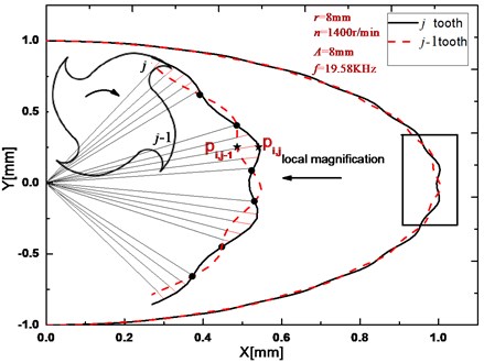
where is feed velocity, is the cutter radius. The motion simulations of two subsequent cutter teeth in feed ultrasonic milling operation have been acquired by Eq. (2). The results are shown in Fig. 1. It can be clearly seen that the trajectories of two subsequent teeth ( tooth and tooth) are continuous intersection, which demonstrate that the current tooth and the workpiece are in state of continuous separation under high frequency.
Fig. 1Milling trajectory simulations of two subsequent cutter teeth
3. Dynamic model of the feed ultrasonic milling
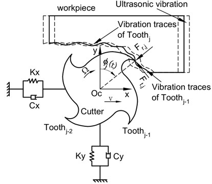
For example end milling, the milling operation is an interaction between the cutter tooth and the workpiece. This is shown in the block diagram of Fig. 2. Considering the vibrations in and directions, the model of tool vibrations can be simplified to a mass-damping-spring mechanical system of two degrees of freedom. The dynamical equations are given by:
where , and () are the system mass, damping and stiffness in and directions respectively, and are the cutting forces on tool in and directions at time, and are the displacement of the cutter in and directions at time.
The cutting forces on the cutter tooth in and directions can be expressed:
where is the rotation angel of the cutter tooth at time: , (), is the spindle speed, and are the tangential and radial forces on the cutter tooth ,respectively.
The tangential and radial forces on the cutter tooth are given by:
where and are tangential and radial cutting parameters respectively, is axial cutting depth, and are tangential and radial of the cutting edge parameters, is the cutting constant, is the dynamic chip thickness considering regeneration effect, is the function that judge whether a tooth is in or out of cut. The tooth is in cut if .
This function is given by:
where and are the start and exit angles, respectively. According to the coordinate frame shown in Fig. 2, for up milling, and ; for down milling, and , where is the radial immersion ratio.
The instantaneous chip thickness is composed of static and dynamic chip thickness. is static chip thickness that the system feed and ultrasonic amplitude in radial direction result in, is the dynamic chip thickness that dynamic displacements of two subsequent teeth result in.
The instantaneous chip thickness, static chip thickness and dynamic chip thickness can be expressed as follows.
where is the cutter tooth passing interval, is window function that judges whether the interact between the cutter tip and the workpiece or not. Its value is one when the cutter tip contacts with the workpiece, or else its value is zero.
Fig. 2The dynamic model of feed ultrasonic vibration milling
The model of feed ultrasonic milling forces adopts exponential model. To predict the system stability, using linear theory of nonlinear periodic function [26], the Eq. (5) can be linearized around and which results in . Then the linearized force can be written as:
with the matrix defined by:
where , and .
So, the dynamic model of feed ultrasonic milling can be expressed by:
where , and are the mass, damping and stiffness matrices, respectively.
4. Stability prediction of the milling system
4.1. The trajectory method
Fig. 1 shows local amplification trajectories of two subsequent cutter teeth in feed ultrasonic milling system. It can be seen that the instantaneous chip thickness is the length along radial direction of the two subsequent teeth trajectories. In Fig. 1, the instantaneous chip thickness is shown in red solid lines, for example . Because of continuous separation between the current cutter tooth and the workpiece in machining, their contact state should be judged. If separation, instantaneous chip thickness doesn’t exist and loses the sense. Here, on the basis of full-discretization method, the authors put forward the trajectory method to judge actual instantaneous chip thickness. The window function is given by:
where , and , are the coordinate values in and directions of the and teeth at and time, respectively. So, it is convenient to use the trajectory method for predicting stability of feed ultrasonic milling system.
4.2. Stability analysis of feed ultrasonic milling system
Substitute and into Eq. (11), it is given by:
where:
with , and () the model mass, the relative damping and the angular natural frequency. , , and are four projections of the specific cutting force coefficient defined as:
Combination the trajectory method above with the full-discretization method, the transition matrix of feed ultrasonic milling system has been achieved. Now, the stability investigation is reduced to the problem, whether the eigenvalues of the transition matrix are in modulus less than one by Floquet theory. The compute parameter is chosen as 40. The radial immersion ratio is 0.05. The stability charts are calculated over a 400×200 sized grid of parameters. Computer programs of the proposed approach are all written in MATLAB7.1 and implemented on a personal computer [Intel Core (TM) i5-3470CPU, 3.2 GHz, 4 GB]. The compute time is about 276.294 seconds.
5. Test verification and results analysis
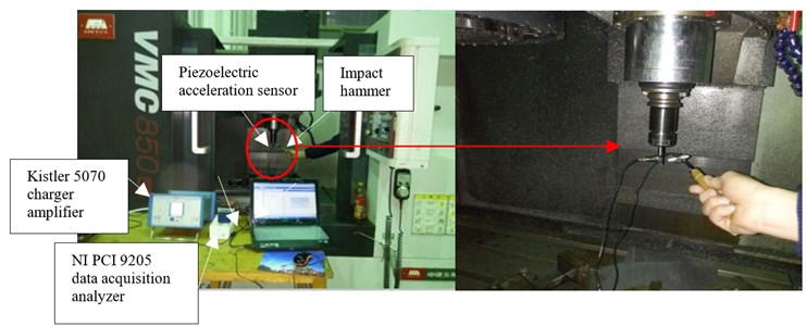
The chatter tests had been made on VMC850 CNC machining center. The end milling with 4 cutter teeth is solid carbide, the cutter diameter is 8mm, helical angle is 30°. For each experiment the part material is Ti6Al4V, 110 GPa, 4505 kg/m3, its size is 30 mm×10 mm×15 mm. The test equipment has Kistler 9257B three component dynamometer, NI PCI9205 data acquisition analyzer, Kistler 5070 charge amplifier, 8207 impact hammer and the piezoelectric acceleration sensor made in Orient Institute. The model parameters of this system have been achieved by impact hammer test using the above device as shown in Fig. 3. These parameters are shown in Table 1. The coefficients of cutting force have been solved by the method in [27]. The coefficients of cutting force are given as follows: 9.23×10⁸ N/m2, 4.95×10⁸ N/m2, 12.64 N/m, 7.95 N/m.
Table 1Model parameters
(kg) | (Ns/m) | (N/m) | |
Fig. 3Photograph of the setup of modal impact tests
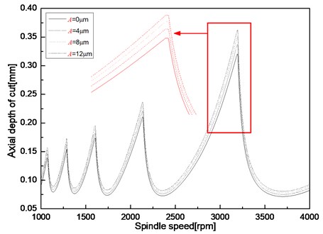
According to the above methods, substitute model parameters and ultrasonic frequency 19.58 KHz into Eq. (13), the stability lobe diagrams are acquired at the different ultrasonic amplitude and shown in Fig. 4. It can be seen that the stability areas of feed ultrasonic milling system are more than that of ordinary milling. As the ultrasonic amplitude increases, the limiting axial depth of cut increases. At about 3200 rpm, the limiting axial depth of cut in stability diagram of ultrasonic amplitude 12 μm increases 15.56 percent compared with that of ordinary milling. However, the increase is very slight since the influence of ultrasonic amplitude as a part of feed on cutting forces is slight. But, the different ultrasonic amplitude can change the contact state of the tool-workpiece.
Fig. 4Stability lobe at different ultrasonic amplitude
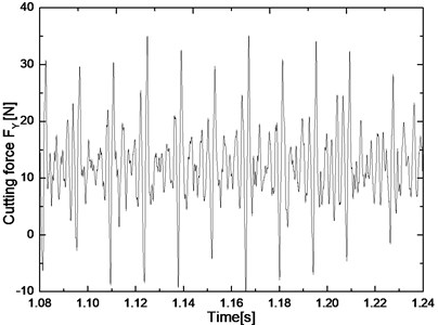
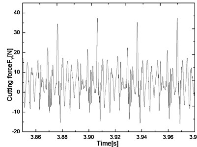
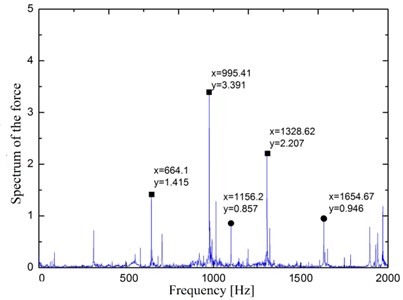
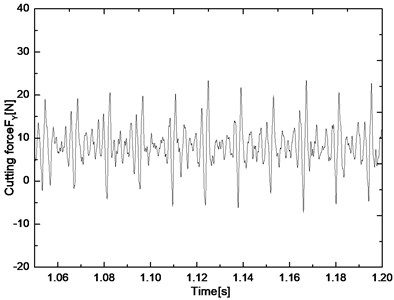
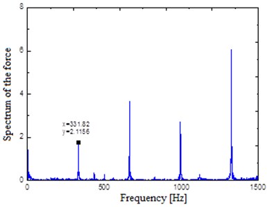
Chatter tests had been conducted as Fig. 5(a) and (b) show. The proving results are shown in Fig. 6. The signs □, ○ and ⊗ are expressed by chatter, stability and slight chatter in the feed ultrasonic milling, respectively. In these experiments, ultrasonic frequency and ultrasonic amplitude are 19.58 KHz and 8 μm. Chatter is determined by examining the force signals and their frequency spectral plots. Tested five-point A, B, C, D, E, they are instability point under ordinary milling but stability point under feed ultrasonic milling. Two examples of the points B and D under ordinary and feed ultrasonic milling respectively are shown in Figs. 7-10. At the point of B, the spindle speed, the radial depth and feed are 1600 rpm, 0.2 mm, and 0.04 mm, respectively. High-frequency variations are evident in the force plot. The frequency spectral plot shows significant energy in the force plot at 128.7 Hz and 235.4 Hz. Since these frequencies are not the tool rotation frequencies or a multiple of the tool rotation frequencies, chatter was present. So, the process of ordinary milling at point B is not stable. But, under feed ultrasonic milling as Fig. 8 shows, there are no high-frequency variations in the force plots. These frequencies that the frequency spectral plot shows significant energy are the tool rotation frequencies and multiples of the tool rotation frequency. So, the operation at point B is stable. At the point of D, the spindle speed, the radial depth and feed are 2500 rpm, 0.4 mm, and 0.06 mm, respectively. In Fig. 9, the frequency spectral plot shows significant energy in the force plot at 1156.2 Hz and 1654.67 Hz. Chatter was present in this operation. So, the operation at point D is not stable under ordinary milling. The same experiment at point D under feed ultrasonic milling had been done and the results are shown in Fig. 10. It can be seen that the operation is stable. The frequency spectral plot shows significant energy at the tool rotation frequencies or a multiple of the tool rotation frequencies. In addition, the pictures of machining surface under ordinary milling and feed ultrasonic milling are shown in Fig. 11. It can be seen that the machining surface at feed ultrasonic milling is more smooth than that of ordinary milling. Under the condition of ordinary milling, the machining surface of the workpiece presents chatter waves. So, the analysis and experimental results demonstrate that under the same machining parameters the feed ultrasonic milling operation is more stable than that of ordinary milling operation.
Test results agree with the simulation results very well by chatter tests. The analysis and experimental results indicate that for all spindle speeds the limiting depth of cut increases as the ultrasonic amplitude increases. The results demonstrate that ultrasonic vibration in feed direction can dramatically suppress the presence of chatter for this end milling operation. The results provide empirical evidence that ultrasonic vibration assisted end milling can improve the stability of the system.
Fig. 5The setup for the chatter tests
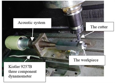
a) Photograph of processing site of the chatter tests
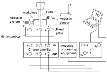
b) Schematic of the setup for the chatter tests
Fig. 6Stability comparison between prediction and experiment results
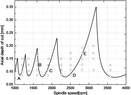
Fig. 7Time-domain signals and frequency spectrum of cutting forces of point B under normal milling
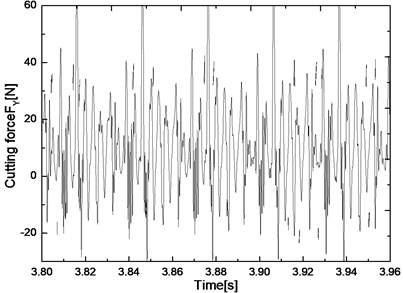
a) Time-domain signals of cutting forces
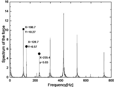
b) Frequency spectrum of cutting forces
Fig. 8Time-domain signals and frequency spectrum of cutting forces of point B under feed ultrasonic milling
a) Time-domain signals of cutting forces
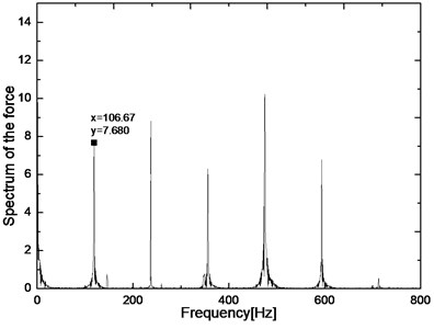
b) Frequency spectrum of cutting forces
Fig. 9Time-domain signals and frequency spectrum of cutting forces of point D under normal milling
a) Time-domain signals of cutting forces
b) Frequency spectrum of cutting forces
Fig. 10Time-domain signals and frequency spectrum of cutting forces of point D under feed ultrasonic milling
a) Time-domain signals of cutting forces
b) Frequency spectrum of cutting forces
The reasons of individual errors are: one is the modal parameters without considering the coupling of and directions; two is the ultrasonic amplitude that can’t guarantee constant in machining, three is to assume that the cutting force coefficients unchanged in the process. However, the above errors do not affect the overall stability trend which is achieved by the 4.1 methods. Because the stability limit has uncertainty, actually the stability limit should be stability belt [28]. So, it is feasible and reliable for applying trajectory method to stability prediction of the separated feed ultrasonic milling system.
It can be also seen from Fig. 6 that with the increase of speed, the limiting axial depth of cut of the slight chatter point is gradually increasing. The higher the speed, the higher is the stability probability of the test points on the border of the stability prediction diagram. With the increase of speed, the cutter tooth passing frequency rises and the time of the cutter tooth left on the workpiece lengthens, which is convenient for the full contact of the cutter tooth and the workpiece and add the instantaneous chip thickness. In addition, ultrasonic vibration that is the varying accelerated motion, makes surrounding contact materials of the workpiece and cutting tool quickly shattered and is conducive to chip shed from the workpiece and cutting tool.
Fig. 11Workpiece surface quality after milling

a) Unstability

b) Stability
6. Conclusions
The full-discretization method introduced by Ding [10] was extended in this paper to consider the effect of ultrasonic vibration in feed direction on end milling operation. Trajectory method has been put forward based on motion characteristics of feed ultrasonic milling. The method was compared to time domain simulation and experimental results for end milling operations. The analyses and experiments results clearly demonstrate that the trajectory method is a simple, practical and high computational efficiency method. It opens up a new way of judging the stability of intermittent cutting.
The analyses provide insight into stability of the separated feed ultrasonic milling system. The results demonstrate that stability region of feed ultrasonic milling system compared to ordinary milling system improves. With the increase of ultrasonic amplitude, stability region is continuous improving, but improving slight. The stability belts have been achieved at different ultrasonic amplitudes. The analyses developed for feed ultrasonic end milling operations compared very well to both time domain simulation and experimental results. The results show that chatter was suppressed under ultrasonic vibration and with the increase of ultrasonic amplitude, the effect of suppressing chatter is better.
References
-
Ai X. High Speed Machining Technology. National Defense Industry Press, Beijing, 2003.
-
Tang J., Zhao B. Stability analysis of the separated longitudinal-torsional composite ultrasonic milling. Acta Armamentarii, Vol. 36, Issue 7, 2015, p. 1319-1325.
-
Altintas Y., Budak E. Analytical prediction of stability lobes in milling. Annals of the CIRP Journal of Manufacturing Science and Technology, Vol. 44, Issue 1, 1995, p. 357-362.
-
Altintas Y. Analytical prediction of three-dimensional chatter stability in milling. Japan Society of Mechanical Engineers, International, Vol. 44, Issue 3, 2001, p. 717-723.
-
Merdol S. D., Altintas Y. Multi frequency solution of chatter stability for low immersion milling. Journal of Manufacturing Science and Engineering-Transactions of the ASME, Vol. 126, Issue 3, 2004, p. 459-466.
-
Altintas Y., Stepan G., Merdol D., Dombovari Z. Chatter stability of milling in frequency and discrete time domain. CIRP Journal of Manufacturing Science and Technology, Vol. 1, Issue 1, 2008, p. 35-44.
-
Insperger T., Mann B. P. Stability of up-milling and down-milling, Part 1: alternative analytical methods. International Journal of Machine Tools and Manufacture, Vol. 43, Issue 1, 2003, p. 25-34.
-
Insperger T., Stepan G. Updated semi-discretization method for periodic delay differential with discrete delay. International Journal for Numerical Methods in Engineering, Vol. 61, Issue 1, 2004, p. 117-141.
-
Henninger C., Eberhard P. Improving the computational efficiency and accuracy of the semi-discretization method for periodic delay-differential equations. European Journal of Mechanics A – Solids, Vol. 27, Issue 6, 2008, p. 975-985.
-
Ding Y., Zhu L. M., Zhang X. J., et al. A full-discretization method for prediction of milling stability. International Journal of Machine Tools and Manufacture, Vol. 50, Issue 5, 2010, p. 502-509.
-
Ding Y., Zhu L. M., Zhang X. J., Ding H. Second-order full-discretization method for milling stability prediction. International Journal of Machine Tools and Manufacture, Vol. 50, Issue 10, 2010, p. 926-932.
-
Ding Y., Zhu L. M., Zhang X. J., Ding H. Numerical integration method for prediction of milling stability. Journal of Manufacturing Science and Engineering, Transactions of the ASME, Vol. 133, Issue 3, 2011, p. 31005-31009.
-
Zhang X. J., Xiong C. H., Ding Y., et al. Milling stability analysis with simultaneously considering the structural mode coupling effect and regenerative effect. International Journal of Machine Tools and Manufacture, Vol. 53, Issue 1, 2012, p. 127-140
-
Ding Y., Zhu L. M., Zhang X. J., Ding H. Stability analysis of milling via the differential quadrature method. Journal of Manufacturing Science and Engineering, Transactions of the ASME, Vol. 135, Issue 4, 2013, p. 044502.
-
Liu Y. L., Zhang D. H., Wu B. H. An efficient full discretization method for prediction of milling stability. International Journal of Machine Tools and Manufacture, Vol. 63, 2012, p. 44-48.
-
Insperger T. Full-discretization and semi-discretization for milling stability prediction: some comments. International Journal of Machine Tools and Manufacture, Vol. 50, 2010, p. 658-662.
-
Guo Q., Sun Y. W., Jiang Y. On the accurate calculation of milling stability limits using third-order full-discretization method. International Journal of Machine Tools and Manufacture, Vol. 62, 2012, p. 61-66.
-
Ozoegwu C. G., Omenyi S. N. Wave attenuation effects on the chatter instability of end-milling. Noise Control Engineering Journal, Vol. 61, Issue 4, 2013, p. 436-444.
-
Huang T., Zhang X. M., Zhang X. J., Ding H. An efficient linear approximation of acceleration method for milling stability prediction. International Journal of Machine Tools and Manufacture, Vol. 74, 2013, p. 56-64.
-
Ozoegwu C. G. Least squares approximated stability boundaries of milling process. International Journal of Machine Tools and Manufacture, Vol. 79, 2014, p. 24-30.
-
Ding Y., Niu J. B., Zhu L. M., Ding H. Numerical integration method for stability analysis of milling with variable spindle speeds. Journal of Vibration and Acoustics-Transactions of the ASME, Vol. 138, 1, p. 2016-11010.
-
Ozoegwu C. G., Omenyi S. N., Ofochebe S. M. Hyper-third order full-discretization methods in milling stability prediction. International Journal of Machine Tools and Manufacture, Vol.92, Issue.3, 2015, p.1 -9.
-
Ozoegwu C. G. High order vector numerical integration schemes applied in state space milling stability analysis. Applied Mathematics and Computation, Vol. 273, 2016, p. 1025-1040.
-
Iglesias A., Munoa J., Ciurana J., et al. Analytical expressions for chatter analysis in milling operations with one dominant mode. Journal of Sound and Vibration, Vol. 375, Issue 4, 2016, p. 403-421.
-
Shen X. H. Study on the Technology and Mechanism of Ultrasonic Vibration Assisted Milling. Shandong University, Shandong, 2011.
-
Faassen R. P. H., van de Wouw N., Oosterling J. A. J., et al. Prediction of regenerative chatter by modeling and analysis of high-speed milling. International Journal of Machine Tools and Manufacture, Vol. 43, 2003, p. 1437-1446.
-
Altintas Y. Manufacturing Automation, Metal Cutting Mechanics, Machine Tool Vibrations, and CNC Design. Cambridge University Press, New York, 2000.
-
Mohammad H. K. Robust Multicriteria Optimization of Surface Location Error and Material Removal Rate in High-speed Milling under Uncertainty. University of Florida, Gainesville, 2005.
About this article

The authors gratefully acknowledge the financial support of the National Science Foundation of China (No. 51475148 and 51175153). The authors also would like to thank the anonymous reviewers for the valuable comments and suggestions to improve the manuscript.
