Abstract
This paper develops an engineering-analytical framework that links roller cone bit nozzle geometry directly to the specific hydraulic energy required per metre drilled. A submerged free-jet decay relation, a cuttings-particle force balance and a Shields-type incipient-motion criterion are coupled to define the minimum wall-jet velocity for cuttings lift-off, which is imposed as a hard constraint in a constrained optimization of the nozzle diameter , inclination angle and stand-off distance . The problem is solved by parametric grid search and five representative configurations are compared. The recommended optimum ( 18 mm, 20°, 50 mm) lowers from 35.95 to 5.04 MJ/m (an 86 % reduction) and raises the predicted rate of penetration from 11.3 to 22.0 m/h (+95 %) relative to a conventional pressure-based arrangement, at the same flow rate and number of nozzles. A one-at-a-time sensitivity study confirms that the optimum is robust to the model calibration constants. Geometry-based redistribution of hydraulic energy is thus more effective, and more sustainable, than pressure-based intensification of the flushing flow.
1. Introduction
Efficient bottomhole cleaning is a key factor in drilling performance, rate of penetration (ROP), bit durability and energy use. In roller cone drilling the flushing system must both deliver fluid to the bottomhole and rapidly remove cuttings from the destruction zone; if cuttings are not evacuated they are re-crushed, causing bit balling, hydraulic losses and tool wear. Nozzle shape and flushing organization strongly affect bottomhole performance [1], as do fluid properties and nozzle orientation [2]. Drilling efficiency depends not only on the energy supplied, but on how rationally it is distributed in rock destruction and cuttings transport [3]; a simple increase in pump pressure may merely raise dissipation and vortex circulation near the bottomhole.
Recent work emphasizes nozzle geometry and jet direction: extended/directional nozzles raise ROP by targeting the impact and improving evacuation [4], curved PDC-bit nozzles redistribute hydraulic energy and improve cleaning and cooling [10], and CFD–DEM studies confirm nozzle diameter, number and inclination as the most influential hydraulic parameters [11], [12]. Energy-efficient drilling is increasingly important because of power demand and carbon footprint [5], [6], [7], [13]. The incipient motion of cuttings is governed by drag, Saffman lift, gravity, buoyancy and inter-particle contact forces [14], [15]. The guiding principle here – improving performance by redistributing the available energy rather than increasing its total input – has methodological precedents in other domains, e.g. power-consumption modelling and optimization-based energy redistribution in traction-power systems [8], [9] (cited only as method analogies, not as drilling references).
The aim of this study is to develop and apply a quantitative rationale for optimizing nozzle geometry in roller cone drilling so as to improve cleaning while reducing specific hydraulic energy. Three specific contributions are made: (i) nozzle geometry is linked directly to the specific hydraulic energy rather than to absolute pressure or jet velocity, reformulating the design task as an energy-efficiency problem; (ii) a minimum wall-jet velocity is derived from the particle force balance and used as a hard constraint; and (iii) a complete three-variable constrained optimization is solved numerically and verified against a conventional baseline.
2. Materials and methods
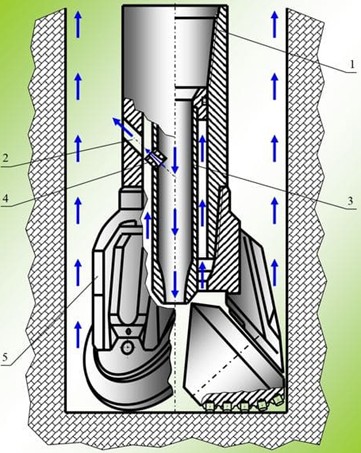
The framework couples an analytical hydrodynamic model with a numerical optimization of nozzle geometry in the bit-bottomhole zone. The flushing scheme and geometric factors are shown in Fig. 1: the nozzle diameter , inclination angle (from the bit axis toward the wall), stand-off distance , flow rate , nozzle pressure drop , fluid density , plastic viscosity and cuttings diameter . In the optimized arrangement the orientation and flow path are chosen to direct the jet along the cuttings-removal path, not only at the rock face.
Fig. 1General scheme of drilling fluid flow in the roller cone bit zone: 1 – drill string; 2 – side channel; 3 – central nozzle; 4 – nozzle; 5 – roller cone. Original figure prepared by the authors
For nozzles of cross-section , the outlet jet velocity follows from continuity and the nozzle pressure drop from a Bernoulli relation with discharge coefficient 0.95; the hydraulic power and total jet impact force are:
Between the outlet and the bottomhole the jet behaves as a submerged turbulent free jet whose centreline velocity decays with distance; with a half-angle of spread /2 = 6°:
For a nozzle tilted by , the radial (transport) component that sweeps cuttings toward the annulus is:
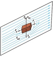
so the radial component is non-zero even at 0 but is small. A single cuttings particle lifts off when drag plus Saffman shear-lift [15] overcome the net submerged weight and inter-particle friction (the force balance is shown in Fig. 2). A Shields-type criterion with combined friction–interlocking factor 1.5 gives the minimum radial velocity:
Fig. 2Force interaction on a cuttings particle in the drilling-fluid flow: Fad – drag; Fa – added-mass; Fas – Saffman shear-lift; Fi – inertial force; Fp – net submerged weight
With 1200, 2600 kg/m3, 3 mm, 0.44, this gives 0.40 m/s. A higher transport (anti-balling) velocity 8 m/s is required to keep the bottomhole swept. The specific hydraulic energy and a two-stage cleaning map (lift-off margin , transport margin ) are:
with 1.5, 0.65 and 22 m/h a representative formation ceiling. The calibration constants are model parameters whose influence is tested in Section 3.4; 0.44 (sphere), 0.95 and the Saffman coefficient 1.615 [15] are standard literature values. The design problem is the constrained minimization:
subject to : (cleaning); : = 20 MPa (pump); : 1000 N (mechanical effect); and bounds [10, 18] mm, [0, 35]°, [40, 80] mm. The non-convex problem was solved by parametric grid search (9×8 points at 50 mm), evaluating Eqs. (1-7) for each candidate and keeping the feasible point of lowest ; the fixed operational values are 30 L/s and 3. The model was implemented in Python (NumPy/Matplotlib) and reproduces every entry of Table 1.
3. Results and discussion
3.1. Mechanism and force balance
Bottomhole cleaning cannot be judged by pressure drop or jet velocity alone. In a conventional scheme ( 0°) the radial component arises only from wall-jet spreading (Eq. (4)), so cuttings linger and are re-crushed. With 0 the nozzle directly produces , one to two orders of magnitude larger, with no extra hydraulic power – the principal reason geometry outperforms pressure. For the reference particle the binding threshold is the transport velocity = 8 m/s rather than 0.40 m/s, so the geometry must raise above .
3.2. Comparison of representative configurations
Several conclusions follow (Table 1). Case A (large straight nozzle) uses only 30.8 kW but its radial velocity (1.42 m/s) is far below , so balling occurs and ROP collapses to 8.4 m/h. Case B – the pressure-based response – triples and , yet (5.27 m/s) still does not reach ; ROP recovers only to 11.3 m/h and rises to 35.95 MJ/m, confirming that hydraulic intensification alone is the worst response to a cleaning problem. Cases C and D share 20° and clear the constraint (ball = 0, ROP = 22 m/h), but D uses 3.7× less power because the larger 18 mm nozzle keeps low while tilt supplies the radial momentum. Case E shows that further intensification beyond the optimum is purely wasteful.
Table 1Quantitative comparison of conventional and optimized nozzle arrangements computed from Eqs. (1)–(7). Row D (highlighted) is the optimum from the parametric search
Case | Description | , mm | , ° | , mm | , m/s | , MPa | , kW | , m/s | ROP, m/h | , MJ/m |
A | Conventional, large nozzle, straight ( 0°) | 18 | 0 | 80 | 39.3 | 1.03 | 30.8 | 1.42 | 8.4 | 13.15 |
B | Conventional, small nozzle, straight (pressure-based) | 13 | 0 | 80 | 75.3 | 3.77 | 113.2 | 5.27 | 11.3 | 35.95 |
C | Tilt-only with small nozzle | 13 | 20 | 50 | 75.3 | 3.77 | 113.2 | 14.25 | 22.0 | 18.52 |
D | Proposed optimum | 18 | 20 | 50 | 39.3 | 1.03 | 30.8 | 8.49 | 22.0 | 5.04 |
E | Over-energized (small nozzle, strong tilt) | 12 | 25 | 45 | 88.4 | 5.20 | 155.9 | 20.90 | 22.0 | 25.52 |
3.3. Optimization result
Fig. 3 shows (solid) and ROP (dashed) versus inclination angle for four diameters at 50 mm. Three regions appear: a sub-feasible region ( ~10°) where balling dominates; an active region (~10-20°) where ROP rises steeply and falls; and a saturation region ( ~20°) where ROP is at its ceiling. The global feasible optimum is 18 mm, 20°, 50 mm, with 5.04 MJ/m, ROP = 22 m/h, 1.03 MPa and 30.8 kW. Relative to the baseline (case A) the tilt alone cuts by 62 % with no change in pressure or flow; relative to the pressure-based case B it cuts by 73 % and by 86 % while raising ROP by 95 %.
3.4. Sensitivity, boundary cases and limitations
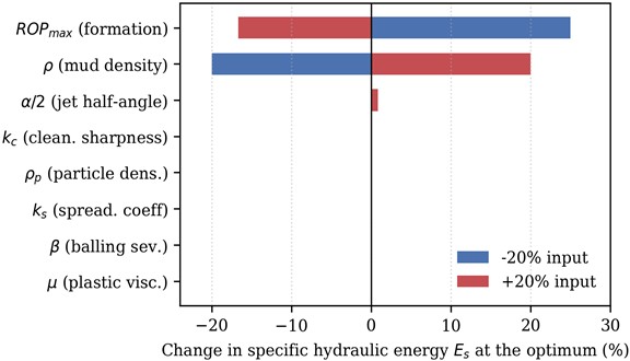
Each input was varied by ±20 % at the optimum (Fig. 4). Es and ROP are insensitive (≈ 0 %) to the particle density and to the calibration constants , , and /2, because the optimum sits deep in the fully-cleaned regime; scales linearly with mud density and inversely with , both physical inputs rather than fitted constants. Plastic viscosity does not enter the lift-off criterion and has no effect. The conclusions are therefore governed by geometry and measurable properties, not by the uncertain constants.
Fig. 3Specific hydraulic energy Es (solid) and predicted ROP (dashed) versus nozzle inclination angle θ for four nozzle diameters, at h= 50 mm, Q= 30 L/s, ρ= 1200 kg/m3, dp= 3 mm. The marker is the global feasible optimum
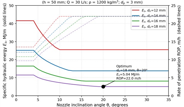
Fig. 4Change in the specific hydraulic energy Es at the optimum for a ±20 % change in each model input (tornado chart)
Two boundary cases were examined. In hard rock (low ) the geometry controls independently of , so the optimum , do not shift; only the absolute rises as 1/, and the saving over a straight jet persists. Under a pump-limited flow rate the minimum tilt to keep above rises (about 19° at 30 L/s to 29° at 20 L/s for an 18 mm nozzle); the energy-optimal response is to reduce the diameter (18 mm at 30 L/s to about 11 mm at 16 L/s), with staying low (3-6 MJ/m). The design rule – increase tilt and trim diameter rather than raise pressure – therefore holds under pump constraints.
The results are from an analytical model not yet validated against experiment, CFD or field data; absolute ROP and are design-screening estimates. The model assumes free-jet decay, a spherical-equivalent single-particle lift-off, steady flow and a formation-limited ROP ceiling, and neglects inter-particle jamming, multi-particle interaction, bit whirl, time-transient flow and non-Newtonian threshold effects. The sensitivity analysis mitigates this by showing robustness to the principal constants, but the validation programme below remains necessary before field use.
4. Conclusions
A closed model couples the nozzle outlet conditions, the submerged free-jet decay law, a Saffman-corrected particle force balance giving the minimum lift-off velocity, and a two-stage cleaning map from wall-jet velocity to ROP. A three-variable constrained optimization with cleaning, pump and mechanical constraints was solved by grid search. The recommended optimum ( 18 mm, 20°, 50 mm) reduces the specific hydraulic energy from 35.95 to 5.04 MJ/m (−86 %) and raises ROP from 11.3 to 22.0 m/h (+95 %) versus a pressure-based arrangement. Geometry-based redistribution of hydraulic energy is more effective and more sustainable than pressure-based intensification: when applied to a cleaning-limited bottomhole, intensification raises pump power without improving ROP and degrades .
Future work will proceed in three phases: CFD-DEM simulation of the bit-bottomhole zone under non-Newtonian rheology benchmarked against this optimum (0-6 months); a laboratory flow-loop with an instrumented bit to calibrate , and against data (6-12 months); and a field pilot with a drilling contractor comparing optimized and conventional arrangements (12-18 months). The model will also be extended to multi-nozzle arrangements with non-identical orientations.
References
-
D. K. Nazarbekova and B. N. Nurtoev, “Influence of the shape of drill bit nozzles in the flushing system of drilling tools to improve their bottomhole performance,” (in Russian), Oil and Gas Uzbekistan, No. 2, pp. 32–41, 2025.
-
D. K. Nazarbekova and B. N. Nurtoev, “Study of drilling fluids and their influence on nozzle orientation in the flushing system of drilling tools,” (in Russian), Inson Kapitali Va Mehnatni Muhofaza Qilish, No. 2(5), pp. 305–310, 2025.
-
D. Nazarbekova and B. Nurtoyev, “Comparative assessment of the effectiveness of methods to increase oil well productivity,” in AIP Conference Proceedings, Vol. 3331, No. 1, p. 030029, Jan. 2025, https://doi.org/10.1063/5.0307221
-
C.-C. Feng, Y. Li, W. Liu, and D.-L. Gao, “Optimization of rate of penetration through improved bit durability and extended directional nozzle,” Petroleum Science, Vol. 22, No. 12, pp. 5114–5127, Dec. 2025, https://doi.org/10.1016/j.petsci.2025.10.007
-
F. E. Dupriest and S. F. Noynaert, “Drilling practices and workflows for geothermal operations,” in IADC/SPE International Drilling Conference and Exhibition, 2022, https://doi.org/10.2118/208798-ms
-
Y. Liu, H. Zheng, and J. Zhang, “Optimization of nozzle spray angle and channel design to improve hydraulic energy distribution in roller cone bits,” Journal of Energy Resources Technology, Vol. 145, No. 8, p. 082104, 2023.
-
X. Meng, H. Zhou, H. Fan, Q. Peng, and S. Deng, “A systematic drilling hydraulics optimization method for improving rate of penetration and its application in ultra-deep wells,” in International Petroleum Technology Conference, 2016, https://doi.org/10.2523/iptc-18829-ms
-
M. Talipov, “Computational modeling and analysis of mechanical power consumption in train assemblers’ work,” in Proceedings of the International Conference on Applied Innovation in IT, Vol. 13, No. 2, pp. 419–426, 2025, https://doi.org/10.25673/120513
-
M. Yakubov, M. Talipov, and U. Nurullaev, “An optimized Lagrangian approach to reactive power compensation in nonlinear traction power-supply systems,” Vibroengineering Procedia, Vol. 60, pp. 724–730, Dec. 2025, https://doi.org/10.21595/vp.2025.25604
-
M. Schnuriger, B. Cuillier, D. Tilleman, and K. Rose, “Curved nozzle design for PDC bits enhances hydraulics for bit cleaning and cooling improvements,” in SPE/IADC Drilling Conference and Exhibition, 2017, https://doi.org/10.2118/184734-ms
-
S. Akhshik, M. Behzad, and M. Rajabi, “CFD-DEM simulation of the hole cleaning process in a deviated well drilling: The effects of particle shape,” Particuology, Vol. 25, No. 1, pp. 72–82, 2016, https://doi.org/10.1016/j.partic.2015.02.008
-
C. Cai et al., “Non-spherical debris cuttings-carrying performance in PDC bits with CFD-DEM coupling method,” Chemical Engineering Research and Design, Vol. 230, pp. 390–403, 2026, https://doi.org/10.1016/j.cherd.2026.04.048
-
Z. Chen et al., “Hydraulic parameters optimization of two-stage PDC bit in deep formation applications,” Geoenergy Science and Engineering, Vol. 230, p. 212248, Nov. 2023, https://doi.org/10.1016/j.geoen.2023.212248
-
W. Hu, N. Guan, J. Zhang, B. Xu, and H. Zhu, “A novel critical velocity model for the incipient motion of non-spherical particles on cuttings bed in extended reach wells,” Particuology, Vol. 97, No. 3, pp. 193–206, 2025, https://doi.org/10.1016/j.partic.2024.12.011
-
A. Seryakov, Y. Ignatenko, and O. B. Bocharov, “Characteristics of a particle’s incipient motion from a rough wall in shear flow of Herschel-Bulkley fluid,” Fluids, Vol. 9, No. 3, p. 65, 2024, https://doi.org/10.3390/fluids9030065
-
L. Esfahanizadeh, B. Dabir, and F. Goharpey, “CFD modeling of the flow behavior around a PDC drill bit: effects of nano-enhanced drilling fluids on cutting transport and cooling efficiency,” Engineering Applications of Computational Fluid Mechanics, Vol. 16, No. 1, pp. 977–994, Dec. 2022, https://doi.org/10.1080/19942060.2022.2026821
About this article

The authors have not disclosed any funding.
The datasets generated during and/or analyzed during the current study are available from the corresponding author on reasonable request.
The authors declare that they have no conflict of interest.

