Abstract
This paper addresses trajectory-oriented excitation of a vibration machine working body by using a planar three-mass oscillatory system driven by a dual, phase-controlled crank-slider mechanism. The working body is assumed to undergo purely translational motion along two orthogonal axes, while two auxiliary masses move along inclined guides and transmit excitation through linear viscoelastic links. An exact kinematic description of the crank-slider base motions is combined with the derived 4-DOF dynamic model to relate the controlled phase shift between the excitation channels to the resulting vibration orbit of the working body. The proposed synthesis framework is formulated in terms of steady-state amplitude and phase relations, enabling intentional generation of rectilinear, elliptical, and circular trajectories. Numerical simulations performed in Wolfram Mathematica demonstrate trajectory switching and continuous steering by adjusting the crank-pin phase offset, the guide orientation angles, and the relative stroke amplitudes of the two excitation branches. The results confirm that phase control provides the primary trajectory-control parameter, while geometric settings rotate the orbit and tune its aspect ratio, with minor deviations from ideal ellipses (circles) attributable to higher harmonics of the crank-slider kinematics.
Highlights
- Developed a 4-DOF dynamic model for a planar three-mass vibratory system driven by a dual phase-controlled crank-slider mechanism.
- Demonstrated that adjusting the inter-channel phase shift allows intentional generation of rectilinear, elliptical, and circular vibration orbits.
- Established that guide orientation angles rotate the vibration orbit, while relative stroke amplitudes control the amplitude balance and incline.
- Identified that minor trajectory deviations from ideal geometric shapes are caused by higher harmonics resulting from the finite rod-length effect.
- Proposed a compact analytical pre-design methodology to systematically shape working-body trajectories for programmable vibratory equipment.
1. Introduction
Trajectory-controlled vibrations of working elements are a key performance driver of modern vibratory equipment for conveying, screening, sieving, and compaction: changing the orbital path (rectilinear, elliptical, or circular) directly affects transport intensity and bed loosening, separation selectivity, and process energy efficiency [1-4]. Recent scientific studies demonstrate both design-oriented approaches to motion-path formation – such as variable-trajectory and flip-flow screens, empirical and analytical assessment of screening-bed behavior, and compactor-medium interaction models – and control-oriented methods for maintaining desired vibration states under changing operating and loading conditions [1-4]. Variable-trajectory and equal-thickness screening concepts can be employed to regulate material distribution over the screening surface and to improve throughput and classification efficiency [5], [6]. For industrial conveyors and screens, multiple excitation concepts are being explored, including crank-type exciters, controllable centrifugal exciters, and crank-driven shaking conveyor-separators with tunable kinematic parameters [7-9]. DEM-based optimization of linear vibrating screens has also shown that vibration amplitude, frequency, direction angle, and deck inclination jointly affect both screening efficiency and screen wear, which highlights the importance of systematic trajectory-oriented design rather than empirical parameter tuning only [10]. For flip-flow screens, higher-fidelity modeling and experimental studies indicate that the realized motion state of the machine may be strongly influenced by the flexible screen panel and by multi-frequency structural response [11].
In parallel, the literature highlights the importance of self-synchronization phenomena, active phase coordination in multi-exciter systems, and trajectory control using semi-active elements such as magnetorheological dampers [12-14]. Independent studies have demonstrated the relevance of frequency-multiplying synchronous control in systems with multiple counter-rotating exciters [15] and have clarified the role of coupling dynamics and energy transfer in multi-body vibrating systems driven by two motors [16]. Nevertheless, analytical trajectory-based synthesis for crank-slider-driven multi-mass systems remains insufficiently developed. Most available studies focus either on screening-process optimization and structural response of vibrating screens [5], [6], [10], [11] or on synchronization of rotor-driven vibrating systems [15], [16], whereas fewer works, particularly [17-21], directly relate the controllable phase offset between two crank-slider excitation channels to the resulting rectilinear, elliptical, or near-circular orbit of a multi-mass working body under the inherently non-harmonic kinematics of a crank-slider drive.
For crank-slider excitation mechanisms, the task of analytically justified trajectory-based synthesis remains insufficiently developed: controllable drive parameters – most importantly the relative phase shift between two excitation channels – should be linked unambiguously to the resulting orbit of a multi-mass working body while accounting for coupled multi-body dynamics and the inherently non-harmonic crank-slider kinematics [17-21]. The present paper addresses this gap by studying a planar three-mass vibratory system excited by a dual phase-controlled crank-slider mechanism. Two auxiliary masses move along inclined guides and transmit excitation to the working body through linear viscoelastic couplings. By combining an exact kinematic description of the imposed base motions with a derived four-degree-of-freedom dynamic model, a synthesis procedure is formulated in terms of steady-state amplitude-phase relations, enabling targeted generation of rectilinear, elliptical, and near-circular trajectories, and quantifying deviations introduced by higher-order kinematic harmonics. Therefore, the major scientific contribution of this work lies primarily at the mechanism-synthesis level: it provides a compact pre-design methodology for trajectory-programmable vibratory equipment rather than a process-specific optimization model.
2. Research methodology
2.1. Mechanism description
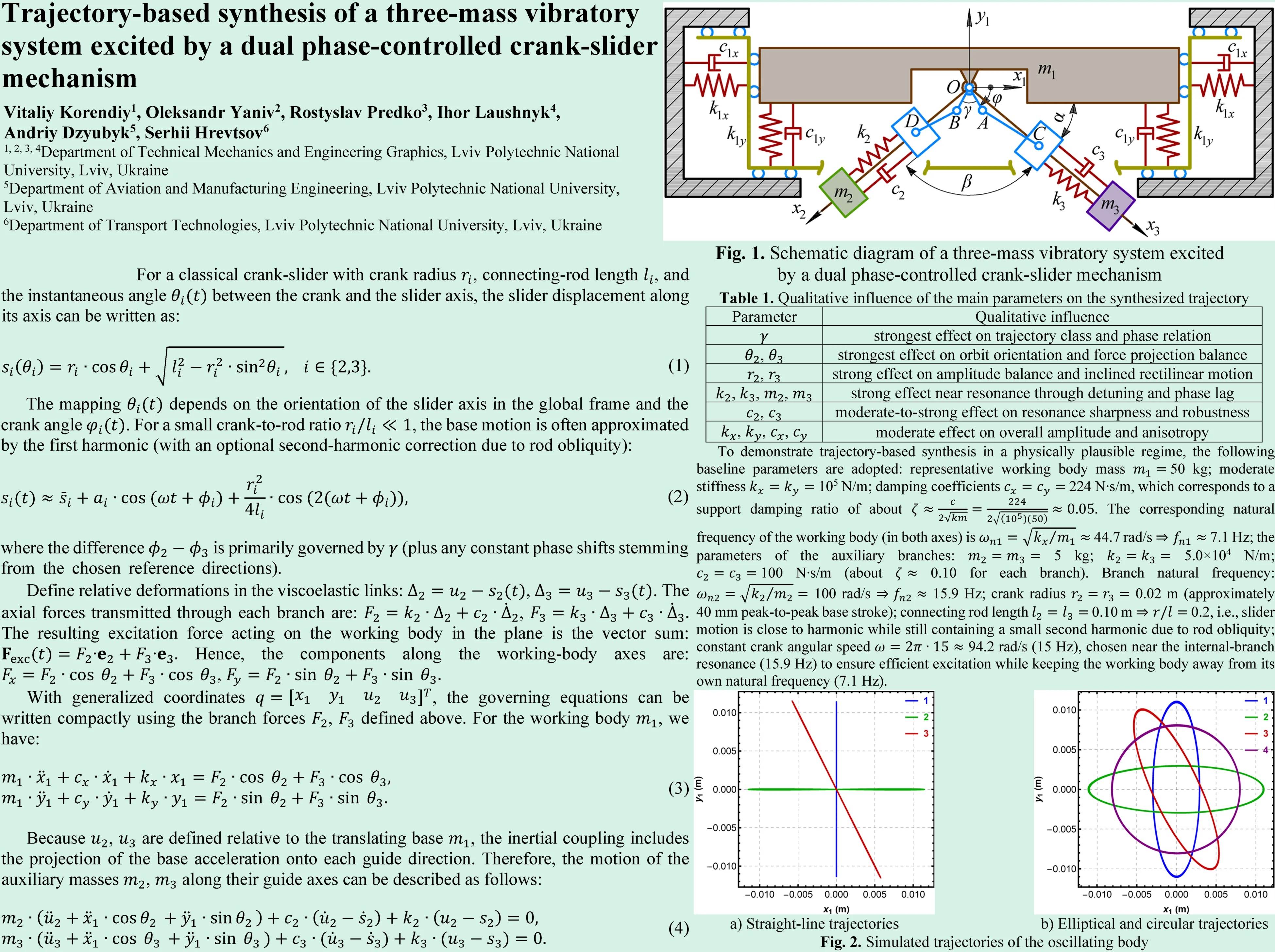
Fig. 1 shows a planar vibro-mechanical system with three moving masses and a two-channel crank-slider excitation mechanism. The working body performs purely translational motion along two mutually orthogonal axes ; angular (rotational) oscillations are neglected. The auxiliary masses and move along two inclined rectilinear guides (axes and ) and are used to excite the motion of in accordance with prescribed vibration laws (rectilinear, elliptical, circular). The sliders of the crank-slider mechanisms are assumed massless. The controlled input is the crank angle , and the crank rotates at constant angular speed . The geometric angles , , and are treated as fixed for a given design (setting), but may take different values across machine configurations to generate different trajectories (vertical, horizontal, inclined lines, ellipses with specified major-axis orientation, circles, etc.).
The working body is mounted on viscoelastic supports that provide restoring and dissipative forces in the horizontal and vertical directions: 1) along : spring-damper pairs on both sides; 2) along : spring-damper pairs on both sides. For symmetric left/right supports, equivalent parameters are conveniently introduced: , , , The generalized coordinates of the working body are: ,
Fig. 1Schematic diagram of a three-mass vibratory system excited by a dual phase-controlled crank-slider mechanism
Each auxiliary mass is coupled to the working body via a linear spring and viscous damper: 1) branch 2: between and the corresponding slider (base); 2) branch 3: between and the corresponding slider (base). Let the guide directions be fixed in the plane. Define unit vectors along the guide axes: , , where and are the guide orientation angles measured with respect to . The included angle between the guides is: Angle in Fig. 1 specifies the orientation of one guide (used to define ), while fixes the relative direction of the second guide. Introduce internal generalized coordinates and , defined as the displacements of and along their guides, relative to the working body.
The above assumptions are adopted intentionally as first-order modeling idealizations suitable for trajectory-oriented synthesis. The linear spring-damper representation of the supports and branch couplings is appropriate for the moderate oscillation amplitudes considered here, because it captures the dominant restoring and dissipative effects while preserving a transparent amplitude-phase interpretation of the resulting motion. The neglect of rotational oscillations of the working body is justified by the symmetric arrangement of the external supports and by the approximately central application of the excitation branches, for which the resultant overturning moment remains secondary compared with the translational force components in the operating regimes studied. Likewise, the slider masses are assumed negligible relative to , , and , so their influence can be omitted at the pre-design stage without obscuring the dominant phase-controlled trajectory-generation mechanism. These assumptions reduce the number of poorly identifiable parameters and make it possible to isolate the effect of the key synthesis variables; their relaxation in a higher-fidelity model is discussed later as part of the study limitations.
2.2. Kinematics of the crank-slider excitation mechanism
The crank angle is prescribed as: , Two crank pins (or two crank radii) generate two base motions. Their relative angular offset is (Fig. 1), hence: , Let and be the slider (base) displacements along the guide axes (these are the imposed motions at the ends of the viscoelastic links). Then: , . For a classical crank-slider with crank radius , connecting-rod length , and the instantaneous angle between the crank and the slider axis, the slider displacement along its axis can be written as:
The mapping depends on the orientation of the slider axis in the global frame and the crank angle . For a small crank-to-rod ratio , the base motion is often approximated by the first harmonic (with an optional second-harmonic correction due to rod obliquity):
where the difference is primarily governed by (plus any constant phase shifts stemming from the chosen reference directions). The second harmonic may distort “ideal” elliptical or circular trajectories; it is minimized by reducing or accounted for explicitly in the synthesis.
Eq. (2) is introduced only to expose the dominant harmonic content relevant for steady-state trajectory synthesis. In the numerical simulations reported in Section 3, the exact crank-slider kinematics of Eq. (1) were retained; therefore, the observed small deviations from ideal ellipses or circles arise from the finite rod-length effect itself rather than from harmonic truncation of the input law.
2.3. Deriving the equations of motion
Define relative deformations in the viscoelastic links: , The axial forces transmitted through each branch are: , The resulting excitation force acting on the working body in the plane is the vector sum: Hence, the components along the working-body axes are: ,
With generalized coordinates , the governing equations can be written compactly using the branch forces , defined above. For the working body , we have:
Because , are defined relative to the translating base , the inertial coupling includes the projection of the base acceleration onto each guide direction. Therefore, the motion of the auxiliary masses , along their guide axes can be described as follows:
The crank-slider mechanisms impose the base motions , . The viscoelastic links convert these imposed motions into branch forces , , which are then projected into and excite the working body. The parameters , (hence , ) shape the force direction, while shapes the relative phase of the two excitation channels.
2.4. Trajectory synthesis of the working body
For steady-state operation at frequency , the working-body motion is commonly represented by the fundamental harmonic: , where , are amplitudes, and , are phases. Define: ,
The trajectory is strictly rectilinear when or For , the line inclination angle with respect to the axis is approximately: A vertical line is achieved when horizontal force components largely cancel, while vertical components add constructively. This is typically promoted by: 1) symmetric guide geometry about the vertical axis (appropriate , ); 2) nearly equal branch dynamics (, , , and comparable base-motion amplitudes); 3) approximately in-phase channel operation: with final adjustment performed considering dynamic phase shifts. Analogously, for horizontal vibration, vertical components are compensated, and horizontal ones are added. This is often supported by: , together with the appropriate guide orientations. Inclined rectilinear vibration requires strict in-phase or anti-phase behavior: , and the desired line inclination follows from the amplitude ratio , which is shaped mainly by , , and the relative branch gains (including frequency-dependent effects).
An ellipse is obtained when both components are nonzero, and the phase shift is neither nor : , , The orientation of the ellipse’s principal axes (rotation of the ellipse in the plane) is given by: This formula is directly useful for designing ellipses whose major axis is vertical, horizontal, or inclined. In practice: 1) is selected to introduce the needed phase offset between channels; 2) , , and the branch dynamics are tuned to obtain the target amplitude ratio and phase shift.
Circular motion is the special case of an ellipse with equal amplitudes and quadrature phase: , This typically demands careful balancing of both channels (geometry, branch parameters) and operating frequency to compensate for dynamic phase lags.
3. Results and discussion
To demonstrate trajectory-based synthesis in a physically plausible regime, the following baseline parameters are adopted: representative working body mass 50 kg; moderate stiffness 105 N/m; damping coefficients 224 N∙s/m, which corresponds to a support damping ratio of about The corresponding natural frequency of the working body (in both axes) is 44.7 rad/s 7.1 Hz; the parameters of the auxiliary branches: 5 kg; 5.0×10⁴ N/m; 100 N∙s/m (about 0.10 for each branch). Branch natural frequency: 100 rad/s 15.9 Hz; crank radius 0.02 m (approximately 40 mm peak-to-peak base stroke); connecting rod length 0.10 m0.2, i.e., slider motion is close to harmonic while still containing a small second harmonic due to rod obliquity; constant crank angular speed 94.2 rad/s (15 Hz), chosen near the internal-branch resonance (15.9 Hz) to ensure efficient excitation while keeping the working body away from its own natural frequency (7.1 Hz).
Numerical simulations were carried out in the Wolfram Mathematica software for the planar three-mass system shown in Fig. 1 using the 4-DOF model (two translational DOF for the working body and one DOF along each guide for and ) based on Eq. (3) and (4). The primary controlled parameter was the crank-pin phase offset , while , (stroke amplitudes) and , (guide orientations, i.e., , ) were used as additional design (setting) parameters to shape the orbit of the working body.
A short robustness discussion is instructive because the adopted nominal regime is intentionally selected close to the auxiliary-branch resonance. In particular, the operating speed 94.2 rad/s is close to the branch natural frequency 100 rad/s, whereas the working-body translational natural frequency remains substantially lower, 44.7 rad/s. Consequently, the synthesized orbit is expected to be most sensitive to the parameters of branches 2 and 3, namely , , , , , and , because they govern both the amplitude of the transmitted excitation forces and the dynamic phase lag between the imposed slider motion and the working-body response. Since , even moderate variations in branch stiffness or auxiliary mass shift the local resonance and may change the aspect ratio and phase relation of the resulting orbit. By contrast, moderate variations of , , , and primarily rescale the response amplitudes and introduce secondary anisotropy, but do not usually alter the trajectory family by themselves.
From this viewpoint, the near-circular regime is the most demanding one, because it requires simultaneous amplitude balance in the two orthogonal directions and an approximately quadrature phase relation. Small mismatches between the two excitation branches therefore appear first as ellipticity or rotation of the orbit. Rectilinear regimes are generally more tolerant, because they require only near in-phase or anti-phase resultant excitation. Hence, the proposed synthesis can be regarded as structurally robust with respect to moderate support-parameter changes, whereas accurate matching of the auxiliary branches becomes more important when operating close to the internal-branch resonance or when high orbit purity is required.
Table 1Qualitative influence of the main parameters on the synthesized trajectory
Parameter | Qualitative influence |
strongest effect on trajectory class and phase relation | |
, | strongest effect on orbit orientation and force projection balance |
, | strong effect on amplitude balance and inclined rectilinear motion |
, , , | strong effect near resonance through detuning and phase lag |
, | moderate-to-strong effect on resonance sharpness and robustness |
, , , | moderate effect on overall amplitude and anisotropy |
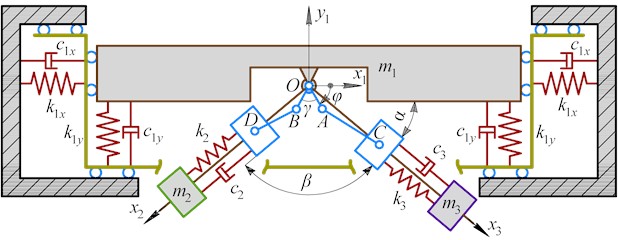
Fig. 2(a) presents three rectilinear trajectories of the working body in the plane (curves 1-3). These regimes are governed by the effective inter-channel phase of the imposed base motions, which for the adopted kinematic reference can be expressed as For the symmetric guide set (–135°, –45°), one has 90°, hence . Rectilinear vibration is obtained when {0°, 180°}, i.e., when the two excitation channels act in-phase or anti-phase; in that case, the resultant excitation force vector oscillates along an almost fixed direction, and the working body motion becomes nearly collinear. The parameter values corresponding to the three rectilinear trajectories in Fig. 2(a) are: 1) curve 1 (vertical line, blue): –90° (0°) with equal strokes 0.02 m. Physically, this setting makes the axial branch forces and nearly equal and in-phase, so that the horizontal projections cancel and the vertical projections add, yielding an almost vertical vibration line; 2) curve 2 (horizontal line, green): +90° (180°) with the same symmetric geometry and equal strokes 0.02 m. Here, the two channels become anti-phase, leading to cancellation of the vertical force components and constructive addition of the horizontal components; therefore, the orbit degenerates into an almost horizontal straight line; 3) curve 3 (inclined line, red): –90° (0°) but with unequal crank radii (stroke amplitudes) 0.01 m, 0.03 m, while all other parameters remain at their baseline values. The in-phase condition preserves rectilinearity; however, the amplitude imbalance between the two branches breaks the perfect cancellation of one force component. As a result, the net excitation is oriented at a fixed inclined direction, and the working body moves along a straight line with a corresponding slope.
Overall, Fig. 2(a) confirms that, for a symmetric guide layout, phase control () selects the principal direction of rectilinear vibration (vertical vs. horizontal), whereas stroke imbalance () enables continuous steering toward inclined straight-line trajectories.
Fig. 2(b) illustrates the transition from elliptical to circular vibration when the effective inter-channel phase departs from 0° and 180°. In this case, the resultant excitation force does not remain collinear but varies its direction over a cycle, which produces a closed planar orbit of the working body. For the symmetric guide arrangement (–135°, –45°), the relationship implies that changing directly tunes , and thus the orbit aspect ratio and orientation. The parameter values corresponding to the trajectories in Fig. 2(b) are: 1) curve 1 (ellipse with major axis approximately vertical, blue): = –60° (30°). This setting yields a strong -component relative to , resulting in a “tall” ellipse; 2) curve 2 (ellipse with major axis approximately horizontal, green): +60° (150°). The orbit becomes “wide”, indicating that the horizontal response dominates while the vertical response is reduced, i.e., the ellipse’s major axis is close to horizontal; 3) curve 3 (inclined ellipse, red): here the ellipse is rotated by changing the guide orientations while keeping the included angle close to : –110°, –20°, 90°, combined with –60°. Rotating the guide layout changes the projection directions of the branch forces onto , which rotates the principal axes of the vibration ellipse and yields the observed inclined orbit; 4) curve 4 (nearly circular trajectory, purple): symmetric guides (–135°, –45°) with 0° (90°). For the adopted geometry, this choice places the two excitation channels close to quadrature in the kinematic input, and, together with balanced branch parameters, produces comparable vibration amplitudes in the and directions, resulting in an orbit close to a circle.
From Fig. 2(b) it follows that is the main “trajectory knob” for switching between families of closed orbits (ellipses → circle → ellipses of opposite aspect), while guide orientation parameters (angles related to and ) provide an additional degree of freedom to rotate the ellipse in the plane without fundamentally changing the excitation architecture. The small deviations from ideal geometric ellipses (circles) can be attributed to the non-sinusoidal component of the crank-slider motion (finite ), which introduces higher harmonics in the imposed base displacements and slightly perturbs the orbit shape.
Fig. 2Simulated trajectories of the oscillating body
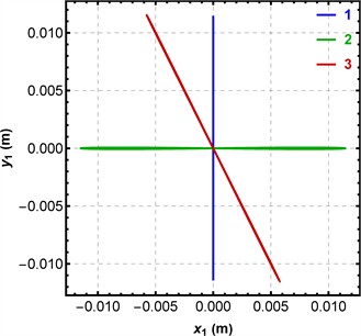
a) Straight-line trajectories
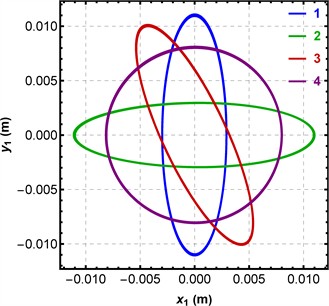
b) Elliptical and circular trajectories
From the practical implementation standpoint, the controlled phase offset should be maintained under varying load conditions if trajectory switching is to remain reliable in a real machine. This may be achieved either by a mechanical transmission with adjustable crank indexing or by electronically synchronized drives operating with encoder-based phase control. In the second case, becomes the real-time control variable, whereas the guide orientations and crank radii remain design settings selected during machine layout. Because the processed material, drive compliance, and transmission elasticity may modify the effective dynamic phase lag of the branches, closed-loop correction based on measured and would be a rational next step for industrial realization of the proposed trajectory-control concept.
At the same time, the present results should be interpreted together with the model limitations. The study is based on numerical simulations of an idealized 4-DOF model and does not yet include finite slider mass, guide friction, support asymmetry, structural compliance, clearances, or interaction between the vibrating body and the processed material. Possible rotational oscillations of the working body were also neglected. Each of these effects may slightly distort the synthesized orbit, especially in operating regimes close to resonance. Therefore, the present contribution should be viewed primarily as a trajectory-synthesis and pre-design framework that identifies the dominant phase-amplitude mechanisms, whereas detailed industrial design still requires experimental validation and higher-fidelity dynamic modeling.
4. Conclusions
A planar three-mass vibratory system excited by a dual crank-slider mechanism has been modeled as a 4-DOF dynamical system with two translational coordinates of the working body and one internal coordinate along each auxiliary guide. This formulation makes it possible to combine the imposed base motions of the crank-slider branches with a compact dynamic description of force transmission through the viscoelastic couplings.
For the adopted kinematic reference, the trajectory class is governed by the effective inter-channel phase . Rectilinear motion is obtained when is close to 0° or 180°, whereas deviations from these values generate closed planar orbits. Within this framework, the phase shift is the principal trajectory-control parameter, the guide orientations determine the projection directions of the branch forces and thus rotate the orbit in the plane, and the relative strokes tune amplitude balance and can be used to produce inclined straight-line trajectories.
When departs from 0° and 180°, the excitation force direction varies over a cycle, and the working body exhibits closed orbits (ellipses and, under balanced conditions, near-circular motion). The phase shift mainly controls the ellipse aspect ratio and the transition “ellipse → circle → ellipse,” while the guide orientation angles (related to , ) enable rotation of the ellipse principal axes in the plane.
The numerical simulations confirm that the proposed mechanism can switch between vertical, horizontal, inclined, elliptical, and near-circular trajectories within a single structural concept. The selected nominal operating regime is effective because it places the excitation frequency close to the internal-branch resonance while remaining sufficiently separated from the main-body translational resonance. At the same time, this near-resonant excitation implies that the matching of the auxiliary branches is more important for orbit purity than moderate changes in the main support parameters, especially when a near-circular trajectory is required.
The present study remains limited to numerical simulations of an idealized model. Finite slider mass, guide friction, support asymmetry, transmission compliance, structural clearances, and possible rotational oscillations of the working body were not included, and the interaction with the processed medium was not considered. These factors may affect the exact shape and stability of the synthesized trajectories in practical machines. Future research should therefore focus on prototype-based experimental validation of the proposed mechanism, identification of real stiffness and damping parameters, and development of synchronization or closed-loop phase-control algorithms for real-time trajectory adjustment under variable operating conditions. Such extensions are necessary to transfer the present trajectory-synthesis framework from analytical pre-design to robust industrial implementation.
References
-
C. Duan et al., “Variable elliptical vibrating screen: Particles kinematics and industrial application,” International Journal of Mining Science and Technology, Vol. 31, No. 6, pp. 1013–1022, Nov. 2021, https://doi.org/10.1016/j.ijmst.2021.07.006
-
V. P. Barbosa, A. L. Menezes, R. Gedraite, and C. H. Ataíde, “Vibration screening: A detailed study using image analysis techniques to characterize the bed behavior in solid-liquid separation,” Minerals Engineering, Vol. 154, p. 106383, Aug. 2020, https://doi.org/10.1016/j.mineng.2020.106383
-
D. Lin, X. Wang, N. Xu, W. Zuo, and Z. Liang, “A method for stabilizing the vibration amplitude of a flip-flow vibrating screen using piecewise linear springs,” Minerals, Vol. 14, No. 4, p. 406, Apr. 2024, https://doi.org/10.3390/min14040406
-
V. Korendiy and O. Kachur, “Dynamic behavior of a vibratory plate compactor working on a horizontal elastic-viscous-plastic surface,” in Lecture Notes in Mechanical Engineering, pp. 434–443, Sep. 2022, https://doi.org/10.1007/978-3-031-16651-8_41
-
H. Jiang et al., “Parameter optimization and spatio-temporal distribution of material for variable trajectory combined equal-thickness screen,” Powder Technology, Vol. 438, p. 119590, Apr. 2024, https://doi.org/10.1016/j.powtec.2024.119590
-
L. Huang et al., “A review of the research on equal thickness screening of material clusters,” Powder Technology, Vol. 467, p. 121531, Jan. 2026, https://doi.org/10.1016/j.powtec.2025.121531
-
O. Kachur and V. Korendiy, “Dynamic behavior of vibratory screening conveyor equipped with crank-type exciter,” in Lecture Notes in Mechanical Engineering, pp. 44–53, May 2023, https://doi.org/10.1007/978-3-031-32774-2_5
-
F. Safranyik, B. M. Csizmadia, A. Hegedus, and I. Keppler, “Optimal oscillation parameters of vibrating screens,” Journal of Mechanical Science and Technology, Vol. 33, No. 5, pp. 2011–2017, May 2019, https://doi.org/10.1007/s12206-019-0403-1
-
V. Osadchyy et al., “Adjustable vibration exciter based on unbalanced motors,” Sensors, Vol. 23, No. 4, p. 2170, Feb. 2023, https://doi.org/10.3390/s23042170
-
O. Afsari and K. Hashemnia, “Optimized design of a linear vibrating screen based on efficiency maximisation and mesh wear minimisation employing discrete element method,” Particuology, Vol. 90, pp. 307–322, Jul. 2024, https://doi.org/10.1016/j.partic.2024.01.004
-
L. Li, Z. Xing, H. Hao, and Z. Yu, “Dynamic analysis and experimental study of the flip-flow vibrating screen (FFVS)’s sieve panel based on membrane vibration theory,” Powder Technology, Vol. 439, p. 119745, Apr. 2024, https://doi.org/10.1016/j.powtec.2024.119745
-
G. Cieplok, “Influence of vibratory conveyor design parameters on the trough motion and the self-synchronization of inertial vibrators,” Open Engineering, Vol. 14, No. 1, Jan. 2024, https://doi.org/10.1515/eng-2022-0434
-
L. Jia, G. Wang, C. Pan, Z. Liu, and X. Zhang, “Controlled synchronization of a vibrating screen driven by two motors based on improved sliding mode controlling method,” PLOS ONE, Vol. 18, No. 11, p. e0294726, Nov. 2023, https://doi.org/10.1371/journal.pone.0294726
-
S. Ogonowski and P. Krauze, “Trajectory control for vibrating screen with magnetorheological dampers,” Sensors, Vol. 22, No. 11, p. 4225, Jun. 2022, https://doi.org/10.3390/s22114225
-
Z. Huang, Z. Zhang, J. Wu, J. Wu, and S. Sun, “Frequency-multiplying synchronous control of the multiple counter-rotating exciters in vibration system,” Journal of Sound and Vibration, Vol. 562, p. 117852, Oct. 2023, https://doi.org/10.1016/j.jsv.2023.117852
-
H. Peng, Y. Hou, and P. Fang, “Stability and coupling dynamic characteristics of a vibrating system with double rigid body driven by two motors considering energy balance,” Journal of Sound and Vibration, Vol. 555, p. 117699, Jul. 2023, https://doi.org/10.1016/j.jsv.2023.117699
-
V. Korendiy, V. Gursky, O. Kachur, V. Gurey, O. Havrylchenko, and O. Kotsiumbas, “Mathematical modeling of forced oscillations of semidefinite vibro-impact system sliding along rough horizontal surface,” Vibroengineering Procedia, Vol. 39, pp. 164–169, Dec. 2021, https://doi.org/10.21595/vp.2021.22298
-
V. Korendiy, V. Gursky, P. Krot, and O. Kachur, “Dynamic analysis of three-mass vibratory system with twin crank-slider excitation mechanism,” Vibrations in Physical Systems, Vol. 34, No. 2, pp. 2023226–1, Jan. 2023, https://doi.org/10.21008/j.0860-6897.2023.2.26
-
V. Korendiy, R. Predko, Y. Danylo, and O. Yaniv, “Analysis of the force and power characteristics of a twin crank-type mechanism of an enhanced vibration exciter,” Vibroengineering Procedia, Vol. 55, pp. 1–7, Sep. 2024, https://doi.org/10.21595/vp.2024.24116
-
V. Korendiy, O. Kachur, R. Predko, O. Kotsiumbas, R. Stotsko, and M. Ostashuk, “Generating rectilinear, elliptical, and circular oscillations of a single-mass vibratory system equipped with an enhanced twin crank-type exciter,” Vibroengineering Procedia, Vol. 51, pp. 8–14, Oct. 2023, https://doi.org/10.21595/vp.2023.23657
-
H. Yan, Y. Li, F. Yuan, F. Peng, X. Yang, and X. Hou, “Analysis of the screening accuracy of a linear vibrating screen with a multi-layer screen mesh,” Strojniški vestnik – Journal of Mechanical Engineering, Vol. 66, No. 5, pp. 289–299, May 2020, https://doi.org/10.5545/sv-jme.2019.6523
About this article

The authors have not disclosed any funding.
The datasets generated during and/or analyzed during the current study are available from the corresponding author on reasonable request.
The authors declare that they have no conflict of interest.
