Abstract
The paper considers an oscillatory system that consists of an elastically supported working member equipped with a ring gear, a carrier, two planet gears, and an eccentric unbalanced mass. A kinematic model of the planetary mechanism is developed to describe the motion of the excitation point and to determine the conditions under which circular, elliptical, straight-line, and hypotrochoidal trajectories can be generated. On this basis, a dynamic model of the vibratory system is formulated in the form of coupled second-order differential equations for the translational motion of the working member. Particular attention is paid to the synthesis of the geometric and kinematic parameters of the exciter, including the gear ratio, eccentricity, carrier arm length, and initial phase angle. The governing equations are solved numerically for representative parameter sets, and the resulting steady-state trajectories of both the working member and the unbalanced mass are analyzed. The results substantiate the condition that represents a boundary case separating single-frequency trajectories from genuine hypotrochoidal motion. The specific parameters governing the transition from circular to elliptical and rectilinear trajectories and determining the number and shape of the lobes in the hypotrochoidal regime are theoretically justified.
Highlights
- Kinematic and Dynamic Modeling: Developed comprehensive kinematic and dynamic models of a planetary-type vibration exciter capable of generating circular, elliptical, and complex hypotrochoidal trajectories.
- Boundary Conditions for Synthesis: Identified the gear ratio R = 2r as the critical boundary case for synthesizing single-frequency elliptical and rectilinear paths through eccentricity and initial phase adjustments.
- Trajectory-Oriented Inverse Design: Established an inverse synthesis procedure that directly links desired trajectory classes, dimensions, and orientations to the mechanical design variables of the planetary mechanism.
- Dynamic Filtering Effects: Demonstrated that elastic-dissipative supports act as dynamic filters, smoothing complex hypotrochoidal paths by suppressing high-frequency features of the unbalanced mass motion.
- Directional Controllability: Justified the use of the initial phase angle as a primary parameter for the directional alignment of rectilinear and elliptical oscillations without modifying the hardware layout.
1. Introduction
Vibratory technological equipment is widely used in screening, conveying, compaction, and finishing processes, where the process efficiency depends not only on vibration amplitude and frequency but also on the trajectory of the working member. A recent review shows that conventional inertial exciters still provide limited trajectory controllability and insufficient adaptability to diverse technological requirements [1]. In this context, planetary-type vibration exciters are of particular interest because they can generate prescribed motion paths by mechanical means. Recent studies have clarified the kinematic structure and geometrical constraints of such mechanisms [2], demonstrated the generation of rectilinear, circular, elliptical, and polygonal trajectories in single-mass systems [3], numerically evaluated the corresponding displacement, velocity, and acceleration characteristics [4], and experimentally confirmed the feasibility of programmable rectilinear trajectories [5]. Among the available approaches, planetary-type vibration exciters are especially promising because they enable trajectory programming at the mechanism level without excessively complicated control hardware while preserving a compact mechanical structure [6].
At the same time, trajectory-oriented synthesis should take into account the nonlinear dynamics of inertial drives with limited-power sources, resonance passage, vibrational capture, and synchronization effects. These aspects were analyzed for slow oscillations in systems with inertial vibration exciters [7], vibrational capture of unbalanced-rotor rotation [8], and resonance single-mass machines with targeted-action exciters operating on the Sommerfeld effect [9]. Application-oriented studies on vibrating screens also confirm that the vibration trajectory substantially affects particle transport and separation efficiency, whether the required path is obtained by semi-active control [10], variable elliptical motion [11], or composite trajectories [12]. However, the available literature still lacks a consistent inverse design procedure that starts from a required motion trajectory and directly determines the rational geometrical and kinematic parameters of a planetary-type vibration exciter. Therefore, this paper is devoted to the trajectory-oriented synthesis of a planetary-type vibration exciter for vibratory technological equipment.
From the viewpoint of vibration theory, the considered planetary-type exciter can be interpreted as a mechanically realized planar multi-frequency excitation source. The first excitation component is generated by the orbital motion of the planet center and is associated with the carrier frequency , whereas the second component is produced by the relative motion of the eccentric mass and is associated with the frequency . Therefore, the trajectory formation problem may be treated as the synthesis of the amplitude ratio, frequency ratio, and phase shift between two orthogonal harmonic inputs. In this sense, the proposed mechanism belongs to the general class of systems whose steady-state motions are governed by frequency commensurability, phase relations, and resonance conditions [13]-[15].
At the same time, the present formulation should be regarded as a reduced-order dynamic model in which the carrier speed is prescribed and the elastic support is assumed linear. Hence, the equations of motion are linear with respect to the working-member coordinates, while the diversity of the obtained trajectories originates from the kinematically synthesized excitation structure. Such an interpretation is consistent with classical nonlinear oscillation and vibrational-mechanics approaches, where interaction of several oscillatory components may generate qualitatively different motion patterns and directional effects [13], [14]. It also clarifies that additional phenomena such as resonance capture, synchronization, or Sommerfeld-type effects become important when the drive dynamics are included explicitly, which is beyond the present scope but represents a natural continuation of this study [16].
Methodologically, the proposed study follows the logic of inverse dynamic design: the desired response is specified first, after which the physically controllable parameters of the mechanism are selected to reproduce this response. Similar model-based reasoning is used in other engineering fields, where parameters are identified or tuned to obtain prescribed dynamic behavior in aeroelastic structures and coupled offshore systems [17], [18]. In the present case, the parameters , , , , and are interpreted not only as geometric quantities, but also as response-shaping design variables.
Accordingly, the aim of this paper is to establish a trajectory-oriented synthesis procedure that links the desired class, size, and orientation of planar working-member motion to the geometric and kinematic parameters of a planetary-type vibration exciter.
2. Research methodology
2.1. Mechanism description
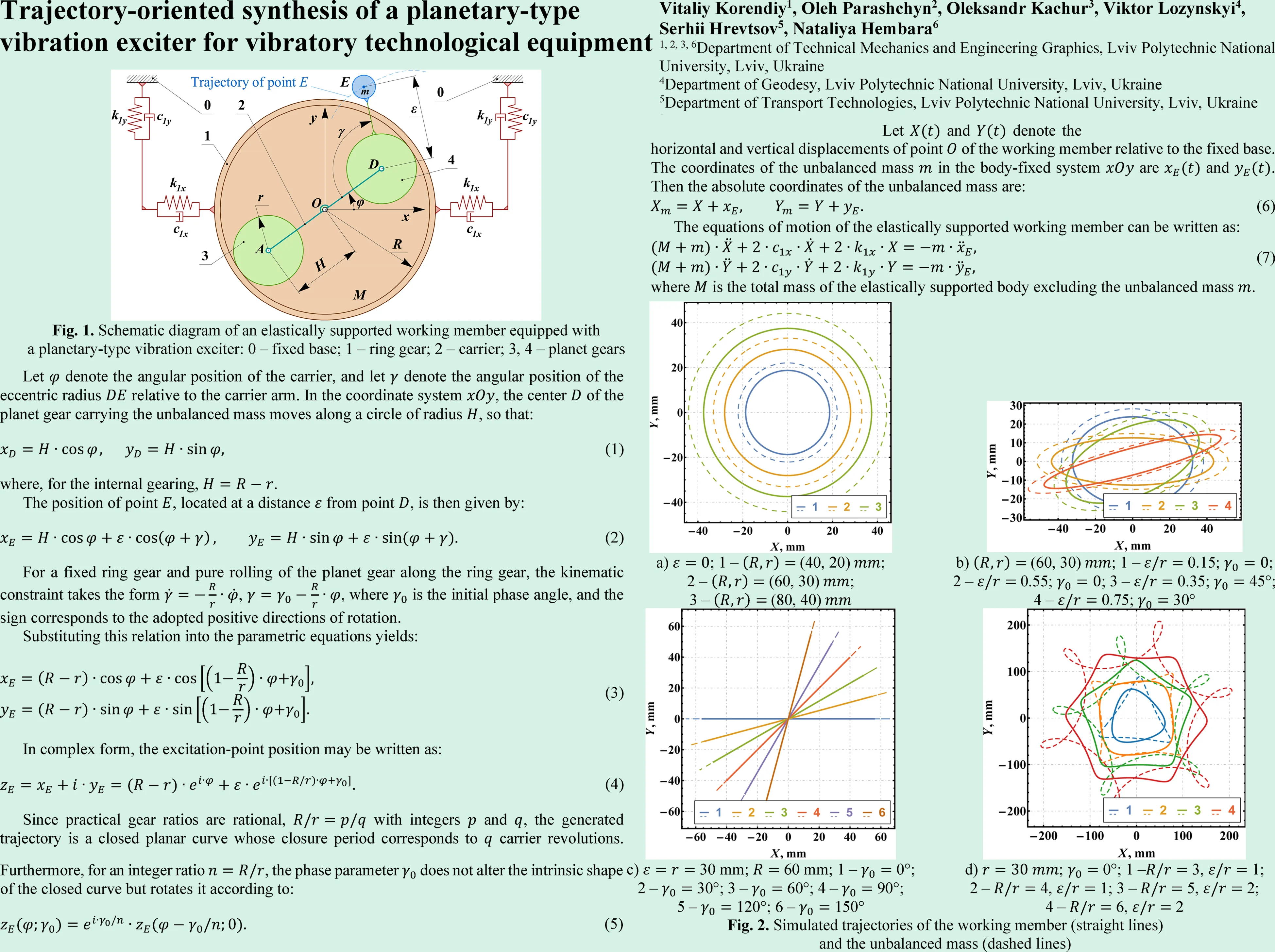
The considered oscillatory system (Fig. 1) consists of an elastically supported working member of total mass , mounted on a fixed base by horizontal and vertical spring-damper supports with stiffness coefficients , and viscous damping coefficients , . A planetary-type vibration exciter is integrated into the working member and comprises ring gear 1, carrier 2, two planet gears 3, 4, and an unbalanced mass located at point with eccentricity .
During operation, the carrier rotates about hinge , while the planet gears simultaneously revolve and spin relative to the ring gear. Owing to this combined motion, point performs a compound planar motion with respect to the working member, which in the general case is hypotrochoidal. As a result, the unbalanced mass generates controlled inertial forces in both the horizontal and vertical directions. By selecting the geometric parameters , , , and , as well as the angular motion parameters and , it is possible to control the amplitude ratio, phase shift, and waveform of the excitation components. This enables trajectory-based synthesis of the working member motion and makes it possible to obtain hypotrochoidal, elliptical, circular, and straight-line trajectories, depending on the technological requirements.
Fig. 1Schematic diagram of an elastically supported working member equipped with a planetary-type vibration exciter: 0 – fixed base; 1 – ring gear; 2 – carrier; 3, 4 – planet gears
2.2. Kinematics of the planetary-type mechanism
Let denote the angular position of the carrier, and let denote the angular position of the eccentric radius relative to the carrier arm. In the coordinate system , the center of the planet gear carrying the unbalanced mass moves along a circle of radius , so that:
where, for the internal gearing, .
The position of point , located at a distance from point , is then given by:
For a fixed ring gear and pure rolling of the planet gear along the ring gear, the kinematic constraint takes the form , , where is the initial phase angle, and the sign corresponds to the adopted positive directions of rotation.
Substituting this relation into the parametric equations yields:
In complex form, the excitation-point position may be written as:
Since practical gear ratios are rational, with integers and , the generated trajectory is a closed planar curve whose closure period corresponds to carrier revolutions. Furthermore, for an integer ratio , the phase parameter does not alter the intrinsic shape of the closed curve but rotates it according to:
Therefore, acts as a trajectory-orientation parameter. The special case 2 immediately yields the rule for elliptical and rectilinear trajectories.
2.3. Dynamics of the vibratory system
Neglecting rotational oscillations of the working member and assuming that the balanced elements of the planetary mechanism do not produce a disturbing force, the system can be represented as a two-degree-of-freedom translational oscillator. Let and denote the horizontal and vertical displacements of point of the working member relative to the fixed base. The coordinates of the unbalanced mass in the body-fixed system are and . Then the absolute coordinates of the unbalanced mass are:
The equations of motion of the elastically supported working member can be written as:
where is the total mass of the elastically supported body excluding the unbalanced mass .
For uniform carrier rotation at the constant angular velocity of the carrier gives , . The relative motion of point is described by Eq. (2), and its acceleration components are:
where the angular velocity of the eccentric radius relative to the fixed coordinate system
Substituting these expressions into the dynamic equations yields:
For the isotropic case and , it is convenient to introduce the complex coordinate . Then Eq. (9) can be rewritten as:
where , and is the initial phase of the second component. This form shows explicitly that the working member is driven by the vector superposition of two circular motions filtered by the same dynamic operator. The corresponding steady-state response may be represented as:
where:
Accordingly, the realized ratio of the two response components is:
Hence, the synthesized working-member trajectory is shaped jointly by the planetary geometry and by the frequency-response properties of the support. In particular, the condition gives and thus a single-frequency response family, whereas leads to a genuine two-frequency regime responsible for hypotrochoidal motion.
2.4. Synthesis of the planetary-type exciter parameters
The trajectory of the working member is determined by the inertial excitation generated by the unbalanced mass moving along the hypotrochoidal path defined by the kinematics of the planetary mechanism. The resulting trajectory of the working member depends on the amplitude ratio and phase relationship between the orthogonal excitation components and . By properly selecting the geometric parameters , , , and , as well as the initial phase , different vibration trajectories can be synthesized.
A particularly important case is , for which the orbital and relative angular motions have equal frequency magnitude. Then, for , the trajectory reduces to:
Which is an ellipse with semi-axes and . Hence, yields a circular trajectory, – an elliptical trajectory, and – a straight-line trajectory as the limiting degenerate case. By contrast, when , the two angular motions become non-isochronous, and point describes a genuine hypotrochoidal path.
More generally, for , Eq. (3) can be transformed to rotated coordinates with the angle :
Therefore, the excitation point moves along an ellipse with semi-axes:
While the initial phase prescribes the ellipse orientation . This yields the inverse synthesis formulas:
For the limiting case , the trajectory degenerates into a straight line.
If the elastic support is nearly isotropic, the steady-state trajectory of the working member remains geometrically similar and differs mainly by the dynamic scale factor:
so that:
Hence, for a prescribed working-member ellipse with semi-axes and , a first design estimate is:
In particular, a rectilinear oscillation of stroke along the direction is obtained from:
For , the excitation-point path becomes an -fold hypotrochoidal curve. In this case, the integer ratio prescribes the lobe number, while the ratio controls the geometric class of the path: produces rounded curtate trajectories, corresponds to the cusp boundary, and yields looped petal-type trajectories. The phase parameter rotates the excitation pattern, whereas the final working-member orientation and dimensions must be verified with the dynamic model because the support introduces frequency-dependent phase shifts at and .
Since the disturbing forces applied to the working member are and , these relations provide the basis for trajectory-oriented synthesis of the exciter. For an approximately isotropic elastic support, the working member reproduces the same family of planar trajectories, whereas the support parameters mainly rescale their amplitudes and introduce phase shifts. The phase parameter can additionally be used to control the spatial orientation of the synthesized ellipse or straight-line path.
Table 1Summary table of parameter-selection rules for the main trajectory families
Target trajectory | Parameter conditions | Direct first-step synthesis rule | Orientation rule |
Circle of radius A | , | , | arbitrary |
Ellipse with semi-axes | , | ||
Straight line of stroke | , | ||
Rounded -lobed path | , | Choose from desired lobe number | Excitation pattern rotated by |
Cusp boundary | , | Boundary case | Excitation pattern rotated by |
Looped or petal -lobed path | , | Increase to obtain outer loops | Excitation pattern rotated by |
3. Results and discussion
The coupled differential Eq. (9) of motion of the elastically supported working member were integrated numerically for the generalized coordinates and under zero initial conditions, i.e., . The baseline parameters of the vibratory system were selected as 35 kg, 8 kg, 4.5×10³ N/m, and 60 N·s/m. Therefore, the total stiffness and damping in each translational direction were 9.0×10³N/m and 120 N·s/m, respectively. For these parameters, the undamped natural frequency of the translational subsystem was 14.47 rad/s. Such a choice ensured an appreciable dynamic response while preserving a nearly isotropic behavior of the working member in the horizontal and vertical directions. The trajectories discussed below were extracted over one closure period of the steady-state response after transient decay. In a Wolfram Mathematica workflow, this model is directly reproducible with NDSolve using an explicit Runge-Kutta scheme for the non-stiff parameter sets considered here.
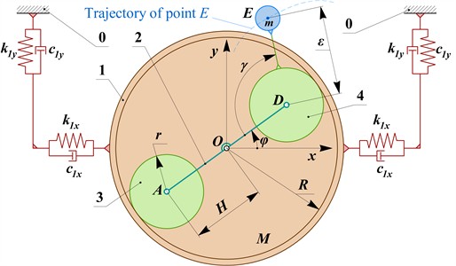
To synthesize circular, elliptical, and straight-line trajectories, the condition was imposed. In this case, the orbital motion of the planet’s center and the relative motion of the eccentric point have equal frequency magnitude, so that the trajectory of the excitation point degenerates from a general hypotrochoid to a single-frequency planar curve. For the circular trajectories, the eccentricity was set to , whereas the pitch radii were varied as (40, 20), (60, 30), and (80, 40)mm at 15 rad/s. The numerical results shown in Fig. 2 demonstrate that the working member follows a family of stable circular trajectories with radii of approximately 18.7, 28.1, and 37.5 mm, respectively. The corresponding trajectories of the unbalanced mass relative to the fixed origin remained geometrically similar and exhibited radii of 22.1, 33.1, and 44.2 mm. Hence, for and , the trajectory synthesis problem reduces essentially to scale selection through the carrier length .
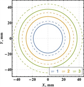
Fig. 2Simulated trajectories of the working member (straight lines) and the unbalanced mass (dashed lines)
a); 1 – (40, 20); 2 – (60, 30); 3 – (80, 40)
b)(60, 30); 1 – 0.15; ; 2 – 0.55; ; 3 – 0.35; 45°; 4 – 0.75; 30°
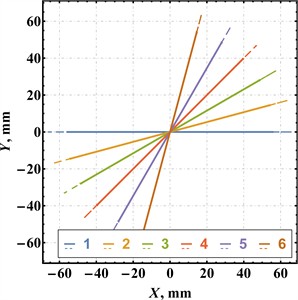
c) 30 mm; 60 mm; 1 – 0°; 2 – 30°; 3 – 60°; 4 – 90°; 5 – 120°; 6 – 150°
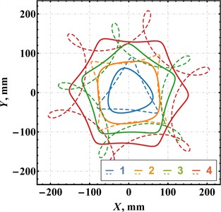
d); 0°; 1 – 3, 1; 2 – 4, 1; 3 – 5, 2; 4 – 6, 2
Elliptical trajectories were obtained for the same pitch radii (60, 30)mm and angular velocity 15 rad/s by varying the normalized eccentricity and the initial phase . Four representative cases were considered: 0.15, 0.55 at 0, and 0.35, 0.75 at 45°, 30°, respectively. As seen from Fig. 2(b), increasing led to a monotonic increase in the trajectory eccentricity of the working member. In particular, the characteristic dimensions of the body trajectory changed from about 64.6×47.8 mm for the first case to 98.3×14.1 mm for the last case. At the same time, the phase parameter rotated the synthesized ellipse without materially altering its size, which confirms that may be used as an orientation parameter rather than as a scaling parameter. The trajectories of the unbalanced mass were consistently larger than those of the working member, but they retained the same elliptical family and orientation trends.
Straight-line trajectories were generated by setting 30 mm while preserving 60 mm and 15 rad/s. Under this condition, the minor semi-axis of the synthesized ellipse collapses to zero, and the motion degenerates into rectilinear oscillation. To demonstrate directional controllability, six values of the phase angle were examined: 0°, 30°, 60°, 90°, 120°, 150°. The numerical results in Fig. 2(c) show six straight-line trajectories of the working member with orientations of approximately 0°, 15°, 30°, 45°, 60°, and 75°, respectively, i.e., one-half of the prescribed initial phase. This agrees with the analytical degeneracy of the ellipse at . The length of the working-member trajectory remained practically unchanged (about 112.4…112.9 mm), while the line orientation was governed almost exclusively by . Therefore, the initial phase of the planetary mechanism provides a convenient means for directional alignment of the working process without modifying the mechanical layout.
To obtain genuine hypotrochoidal motion, the ratio was chosen different from 2, which restores the two-frequency character of the excitation generated by the planetary train. Four representative parameter sets of the planetary mechanism were selected: 1) , ; 2) , ; 3) , ; 4) , , with mm and in all cases. The obtained results show that the first two cases generate rounded triangular and rounded quadrilateral trajectories of the working member, respectively. When the gear ratio is increased to 5 or 6, and the eccentricity is simultaneously increased to , the synthesized motion transforms into five-lobed and six-lobed petal-like trajectories. The corresponding absolute trajectories of the unbalanced mass remain sharper and exhibit pronounced outer loops, whereas the trajectories of the working member are smoother because of the filtering effect of the elastic-dissipative support. Thus, under identical dynamic conditions, the ratio primarily governs the number of lobes of the synthesized path, while the eccentricity controls the transition from polygon-like trajectories to looped petal-type hypotrochoids.
The obtained results also clarify the role of the elastic-dissipative support as a dynamic filter. For the baseline parameters, the carrier frequency 15 rad/s is close to the natural frequency of the translational subsystem, 14.47 rad/s, so the orbital component is appreciably amplified. In the hypotrochoidal regime, however, the second component acts at , i.e., at substantially higher frequencies. As a consequence, this component is attenuated more strongly by the support, and the working-member trajectories become smoother than the absolute trajectories of the unbalanced mass. This explains why the dashed curves in Fig. 2(d) exhibit sharper lobes and outer loops, whereas the solid curves preserve the same trajectory family but in a dynamically filtered form.
4. Conclusions
From a practical design standpoint, the obtained results can be formulated as explicit synthesis rules. Circular, elliptical, and rectilinear trajectories should be generated under the boundary condition , which enforces equal frequency magnitude of the two kinematic components. In this regime, determines the axis ratio according to while fixes the trajectory orientation as . Therefore, a circle is obtained for , an ellipse for , and a straight line for . If the required working-member semi-axes are and , the corresponding first design estimate under nearly isotropic support is , , ,
For genuine hypotrochoidal motion, the condition 2 must be imposed. In that case, the gear ratio becomes the primary parameter governing the lobe number, whereas the ratio governs the transition from rounded trajectories to cusp-like and looped petal-type paths. Consequently, the engineering synthesis procedure may be stated as follows: first choose the required trajectory class; then assign to define the frequency structure and, if needed, the lobe number; next choose to define the axis ratio or lobe sharpness; finally use to orient the trajectory and verify the resulting amplitudes with the dynamic model of the supported body. Under nearly isotropic supports, the working member reproduces the same trajectory family, whereas the support mainly rescales amplitudes and suppresses sharp high-frequency features. Thus, the proposed planetary-type vibration exciter may be regarded as a compact mechanical trajectory-programming device for vibratory technological equipment.
Further research will be focused on the experimental verification of the proposed theoretical model using a laboratory prototype of the vibratory system. It is also planned to extend the model by taking into account rotational oscillations of the working member, possible nonlinearities of the elastic-dissipative supports, and additional effects associated with gear backlash, friction, and manufacturing tolerances of the planetary mechanism. Another promising direction is the optimization of the exciter parameters for specific technological processes that require prescribed amplitude-frequency characteristics and trajectory shapes.
References
-
V. Korendiy et al., “Novel concepts and designs of inertial vibration exciters for industrial vibratory equipment: a review,” Ukrainian Journal of Mechanical Engineering and Materials Science, Vol. 10, No. 4, pp. 17–33, Jan. 2024, https://doi.org/10.23939/ujmems2024.04.017
-
V. Korendiy, O. Parashchyn, V. Heletiy, V. Pasika, V. Gurey, and N. Maherus, “Kinematic analysis and geometrical parameters justification of a planetary-type mechanism for actuating an inertial vibration exciter,” Vibroengineering Procedia, Vol. 52, pp. 35–41, Nov. 2023, https://doi.org/10.21595/vp.2023.23728
-
V. Korendiy, V. Gurey, V. Borovets, O. Kotsiumbas, and V. Lozynskyy, “Generating various motion paths of single-mass vibratory system equipped with symmetric planetary-type vibration exciter,” Vibroengineering Procedia, Vol. 43, pp. 7–13, Jun. 2022, https://doi.org/10.21595/vp.2022.22703
-
V. Korendiy, O. Parashchyn, O. Kotsiumbas, R. Palash, O. Levytska-Revutska, and O. Hrytsun, “Simulation of motion trajectories and kinematic characteristics of an oscillatory system with a planetary-type vibration exciter,” Vibroengineering Procedia, Vol. 58, pp. 31–38, May 2025, https://doi.org/10.21595/vp.2025.24973
-
V. Korendiy, O. Parashchyn, R. Predko, O. Kotsiumbas, and R. Pelo, “Computer simulation and experimental verification of rectilinear motion trajectories of a single-mass oscillatory system actuated by an inertial planetary-type vibration exciter,” Ukrainian Journal of Mechanical Engineering and Materials Science, Vol. 11, No. 3, pp. 1–10, Jan. 2025, https://doi.org/10.23939/ujmems2025.03.001
-
R. Palevicius and K. Ragulskis, “The self-resonance effect of the planetary vibration excitation systems,” Journal of Vibroengineering, Vol. 14, No. 1, pp. 244–249, 2012.
-
N. P. Yaroshevich, O. S. Lanets, and O. M. Yaroshevych, “Slow oscillations in systems with inertial vibration exciters,” Mechanisms and Machine Science, pp. 29–42, Apr. 2022, https://doi.org/10.1007/978-3-030-96603-4_3
-
N. Yaroshevich, V. Grabovets, Yaroshevich, I. Pavlova, and I. Bandura, “On the effect of vibrational capture of rotation of an unbalanced rotor,” Mathematical Models in Engineering, Vol. 9, No. 2, pp. 81–93, Jun. 2023, https://doi.org/10.21595/mme.2023.23273
-
G. Filimonikhin, V. Pirogov, M. Hodunko, R. Kisilov, and V. Mazhara, “The dynamics of a resonance single-mass vibratory machine with a vibration exciter of targeted action that operates on the Sommerfeld effect,” Eastern-European Journal of Enterprise Technologies, Vol. 3, No. 7 (111), pp. 51–58, Jun. 2021, https://doi.org/10.15587/1729-4061.2021.233960
-
S. Ogonowski and P. Krauze, “Trajectory control for vibrating screen with magnetorheological dampers,” Sensors, Vol. 22, No. 11, p. 4225, Jun. 2022, https://doi.org/10.3390/s22114225
-
C. Duan et al., “Variable elliptical vibrating screen: Particles kinematics and industrial application,” International Journal of Mining Science and Technology, Vol. 31, No. 6, pp. 1013–1022, Nov. 2021, https://doi.org/10.1016/j.ijmst.2021.07.006
-
H. Yang and X. Ma, “Research on the screening mechanisms of composite vibrating screens based on discrete elements,” PLOS ONE, Vol. 18, No. 10, p. e0293205, Oct. 2023, https://doi.org/10.1371/journal.pone.0293205
-
A. H. Nayfeh and D. T. Mook, Nonlinear Oscillations. Wiley, 1995, https://doi.org/10.1002/9783527617586
-
I. I. Blekhman, Vibrational Mechanics: Nonlinear Dynamic Effects, General Approach, Applications. World Scientific, 2011, https://doi.org/10.1142/9789812794659
-
J. P. den Hartog, Mechanical Vibration. New York, NY, USA: Dover Publications, 1985.
-
J. M. Balthazar et al., “An overview on non-ideal vibrations,” Meccanica, Vol. 38, No. 6, pp. 613–621, Dec. 2003, https://doi.org/10.1023/a:1025877308510
-
F. Rizzo et al., “Construction and dynamic identification of aeroelastic test models for flexible roofs,” Archives of Civil and Mechanical Engineering, Vol. 23, No. 1, Oct. 2022, https://doi.org/10.1007/s43452-022-00545-y
-
A. Lauria et al., “On the effects of wind and operating conditions on mooring line tensions for floating offshore wind turbine,” Applied Ocean Research, Vol. 152, p. 104197, Nov. 2024, https://doi.org/10.1016/j.apor.2024.104197
About this article

The authors have not disclosed any funding.
The datasets generated during and/or analyzed during the current study are available from the corresponding author on reasonable request.
The authors declare that they have no conflict of interest.
