Abstract
The paper addresses the locomotion analysis of a pantograph-based adaptive wall-pressing in-pipe robot with a slider-crank drive and overrunning clutches. A reduced kinematic scheme is developed using the axial coordinates of two traction modules and the crank angle as the main variables. In contrast to rigidly coupled designs, the pusher acts on one module through a compliant flat spring-damper element, which enables smoother force transmission and more realistic switching transients. On this basis, a hybrid dynamic model is formulated by combining the drive force, friction-limited clutch reactions, rolling resistance, and the axial component of gravity. Simulations are carried out for horizontal, inclined, and vertical pipelines. The obtained results show stable one-way locomotion in all considered cases, while the motion efficiency decreases with increasing inclination. The proposed concept is effective for adaptive in-pipe locomotion, although vertical climbing requires further optimization of the preload and damping parameters.
Highlights
- Model Innovation: A hybrid dynamic model was developed for an in-pipe robot, integrating a compliant slider-crank drive and overrunning clutches.
- Design Advantage: The compliant intermodule connection ensures smoother force transmission and reduces shock loading during clutch switching.
- Locomotion Stability: Simulations confirm the robot achieves stable, directed one-way locomotion across horizontal, inclined, and vertical pipelines.
- Performance Metrics: Locomotion efficiency and average translational speed decrease substantially as pipeline inclination increases due to gravity.
- Kinematic Behavior: Horizontal motion maintains continuous forward drift, whereas inclined and vertical climbing exhibit intermittent progress.
1. Introduction
Mobile in-pipe robots must ensure sufficient traction, reliable centering, adaptability to pipe-diameter variation, and stable locomotion in straight, inclined, and locally irregular pipe sections. Foundational wheeled solutions established differential-drive mobility in urban gas pipelines [1], active pipe-diameter adaptation with automatic tractive-force adjustment [2], and two-module collaborative motion planning for indoor pipelines [3]. Later studies clarified the operating features of novel driving mechanisms and characteristic locomotion regimes [4]. For large-diameter service lines, a wheeled wall-pressing robot demonstrated the decisive roles of preload, traction reserve, obstacle-crossing capability, and vibration attenuation [5]. At the same time, a comprehensive review of mathematical models showed that many in-pipe studies still remain predominantly kinematic or quasi-static, whereas unified dynamic descriptions of actuation, contact, and locomotion are comparatively scarce [6].
Recent research has considerably broadened both mechanical concepts and modeling tools. A lightweight three-module robot PEIS realized worm-like locomotion for inspection and obstruction removal [7], while a cam-linkage inchworm robot achieved bidirectional active wall pressing using a single actuator [8]. In parallel, a dedicated line of dynamic investigations examined vibration-driven wheeled locomotion: forced oscillations of a semidefinite vibro-impact system on a rough surface [9], a mathematical model of a wheeled vibro-impact locomotion system with crank-slider excitation and one-way rolling [10], motion simulation with impact-gap verification for pipeline inspection [11], and the influence of impact-gap value on the average translational speed [12]. These studies proved the importance of excitation law, contact discontinuity, and directional rolling constraints for translational progress.
Adaptive support mechanisms remain a key research direction. A recent review systematized linkage-based wall-pressing adaptation mechanisms [13], SmartCrawler introduced a size-adaptable architecture and a two-phase motion-control algorithm for water distribution systems [14], and a screw-driven robot with a novel adapting mechanism showed improved operation in pipes of variable diameter [15]. Nevertheless, the available literature still lacks a compact hybrid model for a pantograph-based adaptive wall-pressing robot in which slider-crank actuation, radial preload generation, overrunning-clutch switching, and longitudinal locomotion are considered jointly. Therefore, the aim of this paper is to develop such a model and to determine the influence of the main geometrical, elastic, inertial, and frictional parameters on the locomotion characteristics of the proposed robot. The research objectives are to derive the governing kinematic and dynamic relations, simulate locomotion in pipes of constant and variable diameter, and identify parameter ranges ensuring stable traction and efficient motion.
2. Research methodology
2.1. Mechanical architecture and operating principle of the proposed robot
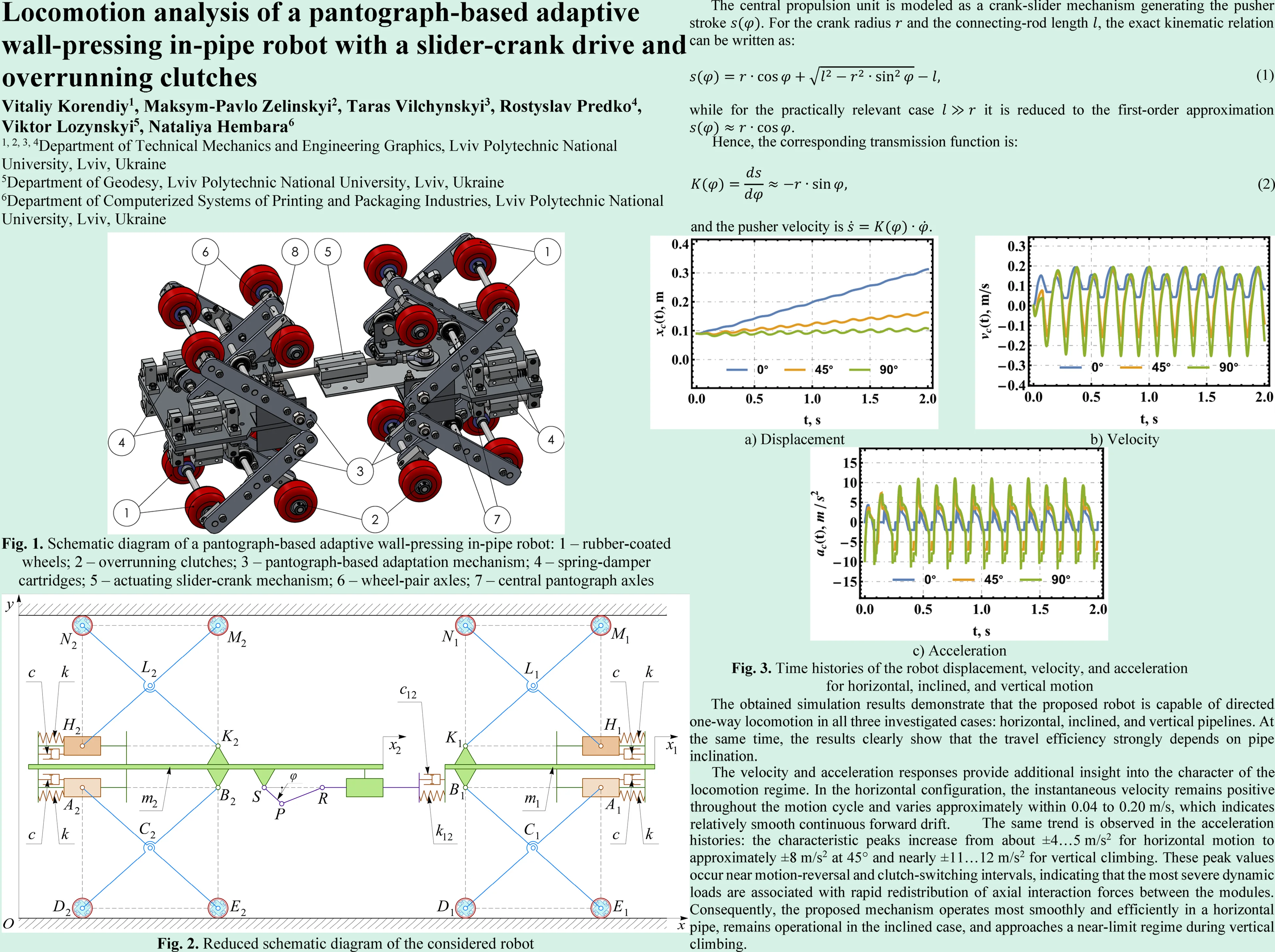
The considered in-pipe robot is a symmetric wall-pressing system composed of two identical traction modules interconnected by a central propulsion unit (Fig. 1). Each module comprises rubber-coated wheels (1) mounted on wheel-pair axles (6) through overrunning clutches (2), a pantograph-based adaptation mechanism formed by crossed levers (3), spring-damper wall-pressing cartridges (4), and a central pantograph axles (7). The crossed-lever arrangement ensures passive self-centering of the robot and adaptation to pipe-diameter variation, while keeping the wheel axes approximately parallel to the robot longitudinal axis and normal to the local pipe radius. The radial preload generated by the spring-damper elements (4) creates the required normal contact force between the wheels (1) and the pipe wall, and the available traction is therefore governed by the corresponding friction force.
Fig. 1Schematic diagram of a pantograph-based adaptive wall-pressing in-pipe robot: 1 – rubber-coated wheels; 2 – overrunning clutches; 3 – pantograph-based adaptation mechanism; 4 – spring-damper cartridges; 5 – actuating slider-crank mechanism; 6 – wheel-pair axles; 7 – central pantograph axles
The propulsion subsystem is based on a slider-crank mechanism (5); however, the end of its pusher is not rigidly attached to one of the traction modules. Instead, the pusher acts on the module through a flat spring (8), so the drive-to-module connection becomes compliant rather than perfectly rigid. Therefore, the crank-slider mechanism should be interpreted not as an ideal displacement-imposing pair, but as an elastic excitation stage that periodically changes the intermodule spacing and transmits axial force through the spring element. Such a solution is expected to smooth force transfer, compensate minor assembly or alignment errors, and reduce shock loading during motion reversal and clutch switching. During the extension phase, the mechanism pushes the modules apart, one clutch set provides support, and the other allows forward wheel rolling; during the contraction phase, the anchoring condition is reversed and the trailing module is pulled toward the leading one. In this way, the reciprocating internal motion is transformed into one-way rolling locomotion without using individual wheel drives. When the robot passes through locally narrowed or widened pipe sections, the pantograph levers (3) fold or open, the spring-damper cartridges (4) adjust the wall-pressing force, and the flat spring (8) additionally softens the axial interaction between the pusher and the module, which is especially important for motion in variable-diameter pipelines.
2.2. Schematic diagram of the considered in-pipe robot
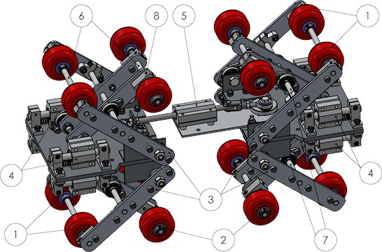
The reduced schematic diagram of the considered robot is shown in the fixed coordinate system , where the -axis coincides with the pipe longitudinal axis and the -axis is directed normally to it (see Fig. 2). The robot consists of two symmetric traction modules, indexed by 1 and 2, whose axial motions are described by the generalized coordinates and , while and denote the corresponding lumped masses of the module frames. Each module includes a central carrier frame, two wall-pressing sliders and , and a pantograph-type adaptation mechanism formed by crossed links. The inner hinges and connect the pantograph to the module frame, the intermediate joints and define the scissor-like motion of the mechanism, and the wheels are located at the outer nodes , , , and . The upper and lower sliders are elastically connected to the frame by spring-damper elements with stiffness and damping coefficient , which generate the required normal pressing force between the wheels and the pipe wall and provide passive adaptation to pipe-diameter variations.
Fig. 2Reduced schematic diagram of the considered robot
The two modules are coupled by a central crank-slider propulsion mechanism. The crank , rotating about the hinge through the angle , drives the connecting rod and the slider , which moves in the guide rigidly attached to module 2. In contrast to an ideal rigid connection, the pusher acts on module 1 through an additional compliant element characterized by stiffness and damping , which models the flat spring coupling between the drive and the module. Therefore, the propulsion system imposes a periodic axial interaction between the modules rather than a perfectly rigid displacement constraint. During operation, this reciprocating internal motion is transformed into directed rolling locomotion by the overrunning clutches integrated into the wheel supports, whereas the pantograph mechanisms simultaneously maintain self-centering and stable wall contact. Such a schematic representation is convenient for deriving the governing kinematic relations and formulating the hybrid dynamic model of the robot motion in pipes of constant and variable diameter.
2.3. Kinematic model of the in-pipe robot
The central propulsion unit is modeled as a crank-slider mechanism generating the pusher stroke . For the crank radius and the connecting-rod length , the exact kinematic relation can be written as:
while for the practically relevant case it is reduced to the first-order approximation .
Hence, the corresponding transmission function is:
and the pusher velocity is . In contrast to the rigidly coupled design, the pusher does not impose the intermodule motion directly, but acts on module 1 through the compliant flat spring-damper pair . Therefore, it is convenient to introduce the actual intermodule spacing:
and the elastic deformation of the coupling:
where is the installation distance between the modules in the reference position. In the limiting case , the updated mechanism degenerates into the classical rigid slider-crank coupling.
To describe the radial adaptation of each module, an opening angle may be assigned to the pantograph. If is the lever length and is the wheel radius, the local kinematic compatibility can be written as:
where is the radial half-span from the module centerline to the wheel center and is the corresponding axial projection of the lever. Since the wheel centers remain in contact with the pipe wall, varies with the local pipe diameter, while determines the current wheelbase of the module. The overrunning clutches transform the reciprocating internal motion into directed rolling locomotion: during one half-cycle one module acts as the anchoring unit and the other advances, whereas during the next half-cycle the anchoring condition is reversed. Thus, the adopted kinematic model explicitly combines crank-driven axial excitation, elastic intermodule coupling, and pantograph-based passive adaptation to variable-diameter pipelines.
2.4. Hybrid dynamic model of the robot locomotion
Considering Eq. (4) and the corresponding derivative, the axial force transmitted by the drive is:
with and denoting the stiffness and damping of the compliant coupling.
The translational dynamics of the modules is described by the force-balance equations:
where and are the longitudinal resistance forces, including rolling resistance and, if required, the axial component of gravity. The terms and represent the phase-dependent reactions generated by the overrunning clutches. Their admissible values are limited by the wall-contact condition:
where is the resultant normal force produced by the spring-damper wall-pressing elements of the -th module. In the reduced model, the pantograph adaptation is introduced implicitly through these normal reactions, which vary with the local pipe diameter and the corresponding spring compression.
The total longitudinal resistance acting on each module is represented as the sum of rolling resistance and the gravity component along the pipe axis:
where is the rolling-resistance coefficient and is the pipe inclination angle.
The model is hybrid because the governing equations switch depending on the sign of the relative drive velocity . During the extension phase , the rear module acts as the anchoring unit, so that , , and, in the ideal-clutch approximation, . During the contraction phase , the anchoring condition is transferred to the front module, i.e., , , and . Thus, the reciprocating internal motion generated by the slider-crank mechanism is transformed into a directed one-way rolling locomotion. Compared with the rigidly coupled scheme, the additional compliant element allows the model to capture smoother force transmission and more realistic switching transients.
3. Results and discussion
Representative simulations were performed for three orientations of the pipe axis, namely 0°, 45°, and 90°. The reduced model was assigned the following parameters: 1.2 kg; equivalent radial wall-pressing stiffness 1.8 kN/m and damping 12 N·s/m for each cartridge; initial spring compression 18 mm, which provided the resultant normal force 130 N. The compliant drive coupling was characterized by 1.1 kN/m and 28 N·s/m. The slider-crank excitation was defined by the crank radius 16 mm, connecting-rod length 90 mm, and angular speed 20 rad/s. The wheel-pipe friction coefficient was set to 0.42, the rolling-resistance coefficient to 0.018, and the clutch-switching regularization to 12 kN/m and 80 N·s/m.
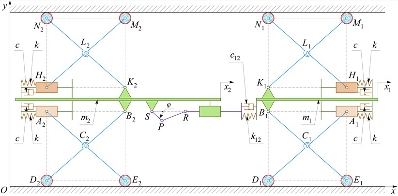
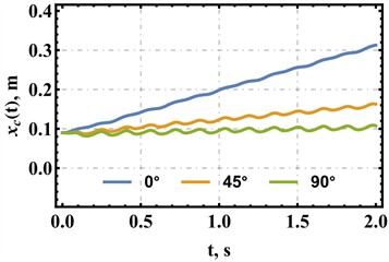
Fig. 3 presents the time histories of the robot displacement , velocity , and acceleration for three pipeline orientations: horizontal (0°), inclined (45°), and vertical (90°). For the adopted parameter set, the robot preserves a positive net displacement in all cases; however, the locomotion efficiency decreases markedly with increasing inclination angle. In the horizontal pipe, the center displacement increases almost linearly from approximately 0.09 m to 0.315 m during the first 2 s, which corresponds to an average speed of about 0.11 m/s. In the inclined case (45°), the displacement reaches about 0.165 m, yielding an average speed close to 0.04 m/s. For the vertical motion (90°), the net displacement is much smaller and reaches only about 0.11 m, so the average upward speed does not exceed 0.01 m/s. Therefore, a substantial part of the available traction in the inclined and vertical modes is spent compensating the gravitational load.
Fig. 3Time histories of the robot displacement, velocity, and acceleration for horizontal, inclined, and vertical motion
a) Displacement
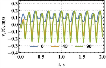
b) Velocity
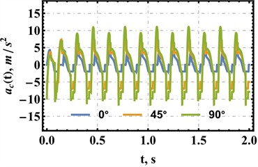
c) Acceleration
The velocity histories are strongly oscillatory and have the same dominant frequency determined by the slider-crank excitation. In the horizontal case, the instantaneous velocity remains positive and varies approximately within the range 0.04…0.20 m/s, which indicates a continuous forward drift of the robot center. In contrast, the inclined and vertical modes exhibit periodic short-term backward motion: in the 45° case, the velocity changes roughly from –0.15 to 0.18 m/s, whereas in the vertical case it varies from about –0.25 to 0.20 m/s. Hence, with increasing inclination, the motion becomes more intermittent, and the forward progress is achieved only due to a positive mean value over the excitation cycle.
The acceleration responses clearly demonstrate the growth of dynamic loading. For the horizontal motion, the acceleration remains within approximately ±4…5 m/s2. In the 45° mode, the extrema increase to about ±8 m/s2, while in the vertical case they reach nearly ±11…12 m/s2. These peaks are observed near the stroke-reversal instants and clutch-switching intervals, when the compliant intermodule coupling rapidly redistributes the axial interaction force. Thus, the obtained results confirm that the proposed robot provides the highest efficiency and the smoothest motion in the horizontal pipeline, remains operational in the inclined pipe, and is still capable of vertical climbing, although in the latter case the regime is close to the limiting one and requires further optimization of the radial preload, coupling damping, and excitation frequency.
4. Conclusions
A reduced kinematic scheme and a hybrid dynamic model of the proposed pantograph-based adaptive wall-pressing in-pipe robot have been developed. In contrast to conventional rigidly coupled solutions, the present formulation explicitly includes a compliant flat-spring connection between the slider-crank pusher and one of the traction modules, together with friction-limited overrunning-clutch reactions, rolling resistance, and the axial component of gravity. Owing to this, the model captures not only the basic reciprocating excitation of the propulsion unit, but also the physically important switching transients that occur during stroke reversal and clutch engagement. From a design perspective, this confirms that the compliant coupling is not merely an auxiliary structural element, but a functionally significant component that improves the realism of force transmission and creates more favorable conditions for adaptive locomotion in pipes of different orientations.
The obtained simulation results demonstrate that the proposed robot is capable of directed one-way locomotion in all three investigated cases: horizontal, inclined, and vertical pipelines. At the same time, the results clearly show that the travel efficiency strongly depends on pipe inclination. According to the simulated displacement histories, the robot center in the horizontal pipe moves from approximately 0.09 m to 0.315 m during the first 2 s of motion, which corresponds to an average translational speed of about 0.11 m/s. When the pipe inclination increases to 45°, the final displacement reaches only about 0.165 m, and the average speed decreases to roughly 0.04 m/s. In the vertical case, the final displacement is about 0.11 m, while the average upward speed does not exceed approximately 0.01 m/s. Hence, the robot preserves positive net motion even under the most unfavorable studied orientation, but the useful forward progress decreases substantially as the gravitational contribution becomes comparable to the available traction reserve.
The velocity and acceleration responses provide additional insight into the character of the locomotion regime. In the horizontal configuration, the instantaneous velocity remains positive throughout the motion cycle and varies approximately within 0.04 to 0.20 m/s, which indicates relatively smooth continuous forward drift. In contrast, the 45° and 90° cases exhibit intermittent motion with short-term backward phases: the velocity changes roughly from −0.15 to 0.18 m/s in the inclined pipe and from about −0.25 to 0.20 m/s in the vertical pipe. Therefore, in these modes the robot advances not because its motion is monotonic at every instant, but because the cycle-averaged displacement remains positive. The same trend is observed in the acceleration histories: the characteristic peaks increase from about ±4…5 m/s2 for horizontal motion to approximately ±8 m/s2 at 45° and nearly ±11…12 m/s2 for vertical climbing. These peak values occur near motion-reversal and clutch-switching intervals, indicating that the most severe dynamic loads are associated with rapid redistribution of axial interaction forces between the modules. Consequently, the proposed mechanism operates most smoothly and efficiently in a horizontal pipe, remains operational in the inclined case, and approaches a near-limit regime during vertical climbing.
The practical significance of the study lies in showing that stable in-pipe locomotion can be achieved without individual wheel drives, using only reciprocating internal motion, adaptive wall pressing, and one-way clutch action. This confirms the feasibility of the proposed pantograph-based concept for compact inspection and service robots intended for pipelines with varying orientation. At the same time, the numerical results indicate that the decisive design parameters are the radial preload generated by the wall-pressing mechanism, the stiffness and damping of the compliant intermodule coupling, and the excitation characteristics of the slider-crank drive. Their proper selection determines whether the system operates in a smooth high-efficiency regime or in a strongly oscillatory regime with increased dynamic loading and reduced average speed. Thus, the main engineering conclusion is that further performance improvement should focus not on changing the general locomotion principle, but on fine-tuning these parameters so as to increase traction utilization and suppress unfavorable transient effects.
The above conclusions should, however, be interpreted in light of the assumptions adopted in the present study. The developed model is reduced-order in nature: the two traction units are represented by lumped masses, the compliant axial interaction is modeled by a linear spring-damper element, the wall-pressing cartridges are described by equivalent linear stiffness and damping, and rolling resistance is introduced through a simplified coefficient-based law. In addition, the pantograph adaptation is incorporated implicitly through the normal reaction rather than through a full multibody description of all links and wheel contacts, while clutch operation is idealized through phase-dependent anchoring conditions with regularized switching. These assumptions are justified at the stage of conceptual analysis because they make it possible to isolate the dominant factors governing locomotion and to compare operating modes under different inclinations. Nevertheless, they also limit the predictive completeness of the model. In particular, the present formulation does not fully resolve such effects as local wheel slip, detailed contact deformation, possible asymmetry between modules, surface roughness variation, wear of frictional interfaces, actuator torque limitations, or the influence of bends, joints, elbows, reducers, contaminants, and fluid media inside real pipelines. Moreover, the reported conclusions are based on simulation results and therefore still require experimental confirmation.
In view of these limitations, further research should proceed in several complementary directions. First, a systematic parametric optimization of radial preload, coupling stiffness, coupling damping, crank radius, and excitation frequency should be carried out in order to maximize average speed and minimize acceleration peaks, especially for steeply inclined and vertical pipes. Second, the model should be extended to more realistic operating conditions, including variable-diameter sections, curved pipeline segments, nonuniform friction, and nonideal clutch switching. Third, the influence of actuator power consumption, structural stresses, and long-term durability of the compliant coupling and wall-pressing elements should be assessed. Finally, the most important next step is experimental validation on a physical prototype, since only a combination of simulation and experiments can establish the practical accuracy of the proposed hybrid model and quantify the real advantages of the compliant-coupling concept over rigidly connected designs. In this sense, the present paper should be considered not as a final description of the robot behavior, but as a solid theoretical basis for subsequent optimization, prototyping, and validation of adaptive in-pipe locomotion systems.
References
-
S.-G. Roh and H. R. Choi, “Differential-drive in-pipe robot for moving inside urban gas pipelines,” IEEE Transactions on Robotics, Vol. 21, No. 1, pp. 1–17, Feb. 2005, https://doi.org/10.1109/tro.2004.838000
-
Y. Zhang and G. Yan, “In-pipe inspection robot with active pipe-diameter adaptability and automatic tractive force adjusting,” Mechanism and Machine Theory, Vol. 42, No. 12, pp. 1618–1631, Dec. 2007, https://doi.org/10.1016/j.mechmachtheory.2006.12.004
-
Y.-S. Kwon and B.-J. Yi, “Design and motion planning of a two-module collaborative indoor pipeline inspection robot,” IEEE Transactions on Robotics, Vol. 28, No. 3, pp. 681–696, Jun. 2012, https://doi.org/10.1109/tro.2012.2183049
-
Q. Liu, T. Ren, and Y. Chen, “Characteristic analysis of a novel in-pipe driving robot,” Mechatronics, Vol. 23, No. 4, pp. 419–428, Jun. 2013, https://doi.org/10.1016/j.mechatronics.2013.03.004
-
G. Feng, W. Li, H. Zhang, Z. Li, and Z. He, “Development of a wheeled and wall-pressing type in-pipe robot for water pipelines cleaning and its traveling capability,” Mechanics, Vol. 26, No. 2, pp. 134–145, Apr. 2020, https://doi.org/10.5755/j01.mech.26.2.18783
-
M. Z. Ab Rashid, M. F. Mohd Yakub, S. A. Zaki Bin Shaikh Salim, N. Mamat, S. M. Syed Mohd Putra, and S. A. Roslan, “Modeling of the in-pipe inspection robot: A comprehensive review,” Ocean Engineering, Vol. 203, p. 107206, May 2020, https://doi.org/10.1016/j.oceaneng.2020.107206
-
M. Salvatore, A. Galloro, L. Muzzi, G. Pullano, P. Odry, and G. Carbone, “Design of PEIS: a low-cost pipe inspector robot,” Robotics, Vol. 10, No. 2, p. 74, May 2021, https://doi.org/10.3390/robotics10020074
-
Q. Xie, S. Liu, and X. Ma, “Design of a novel inchworm in-pipe robot based on cam-linkage mechanism,” Advances in Mechanical Engineering, Vol. 13, No. 9, pp. 1–11, Sep. 2021, https://doi.org/10.1177/16878140211045193
-
V. Korendiy, V. Gursky, O. Kachur, V. Gurey, O. Havrylchenko, and O. Kotsiumbas, “Mathematical modeling of forced oscillations of semidefinite vibro-impact system sliding along rough horizontal surface,” Vibroengineering Procedia, Vol. 39, pp. 164–169, Dec. 2021, https://doi.org/10.21595/vp.2021.22298
-
V. Korendiy, V. Gursky, O. Kachur, P. Dmyterko, O. Kotsiumbas, and O. Havrylchenko, “Mathematical model and motion analysis of a wheeled vibro-impact locomotion system,” Vibroengineering Procedia, Vol. 41, pp. 77–83, Apr. 2022, https://doi.org/10.21595/vp.2022.22422
-
V. Korendiy et al., “Motion simulation and impact gap verification of a wheeled vibration-driven robot for pipelines inspection,” Vibroengineering Procedia, Vol. 41, pp. 1–6, Apr. 2022, https://doi.org/10.21595/vp.2022.22521
-
V. Korendiy, O. Kachur, V. Gurskyi, and P. Krot, “Studying the influence of the impact gap value on the average translational speed of the wheeled vibration-driven robot,” Engineering Proceedings, Vol. 24, No. 1, p. 25, Sep. 2022, https://doi.org/10.3390/iecma2022-12897
-
C. Rusu and M. O. Tatar, “Adapting mechanisms for in-pipe inspection robots: a review,” Applied Sciences, Vol. 12, No. 12, p. 6191, Jun. 2022, https://doi.org/10.3390/app12126191
-
S. Kazeminasab and M. K. Banks, “SmartCrawler: a size-adaptable in-pipe wireless robotic system with two-phase motion control algorithm in water distribution systems,” Sensors, Vol. 22, No. 24, p. 9666, Dec. 2022, https://doi.org/10.3390/s22249666
-
J. Yin, X. Liu, Y. Wang, and Y. Wang, “Design and motion mechanism analysis of screw-driven in-pipe inspection robot based on novel adapting mechanism,” Robotica, Vol. 42, No. 4, pp. 1297–1319, Mar. 2024, https://doi.org/10.1017/s0263574724000316
About this article

The authors have not disclosed any funding.
The datasets generated during and/or analyzed during the current study are available from the corresponding author on reasonable request.
The authors declare that they have no conflict of interest.
