Abstract
The study of beam vibrations under the influence of a moving locomotive requires the use of advanced mathematical methods. This paper focuses on the application of moving nodes in the finite element method (FEM). The Newmark method used in this work allows for high accuracy and stability of the numerical solution. Real conditions of beam support are taken into account using eccentricities. The calculation scheme takes into account the interaction of the beam with the supporting parts by modelling fixed and moving joints. This allows the mathematical model to closely approximate the description of dynamic processes. As the horizontal speed increases, the amplitude of vertical vibrations increases, which leads to an increase in the dynamic coefficient.
Highlights
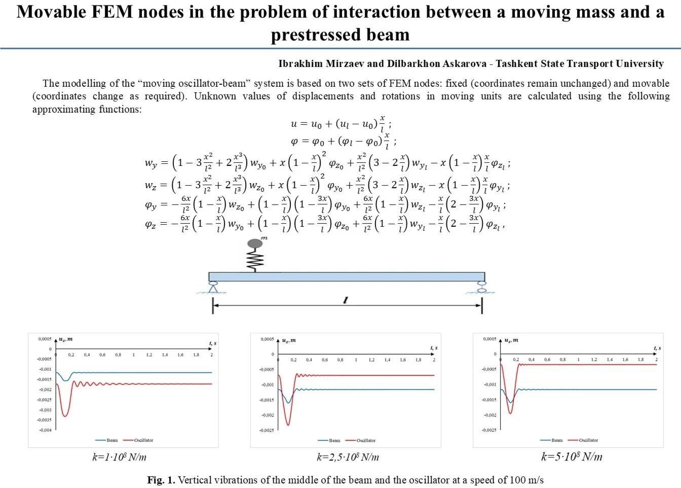
- The modelling of the “moving oscillator-beam” system is based on two sets of FEM nodes: fixed (coordinates remain unchanged) and movable (coordinates change as required).
- Unknown values of displacements and rotations in moving units are calculated using the following approximating functions.
- Vertical vibrations of the middle of the beam and the oscillator at a speed of 100 m/s.
1. Introduction
Modern developments in transport infrastructure dictate strict requirements for the operation of engineering structures. With train speeds constantly increasing, the issue of dynamic stability of bridge structures is shifting from theoretical research to practical safety considerations. Reinforced concrete bridges, which form the basis of the railway network, are subject to enormous vibration loads. At the same time, traditional static calculation methods are no longer capable of fully reflecting the actual stress-strain state of the structure. It is important to understand that each bridge structure has its own unique characteristics of stiffness and frequency parameters.
Today, the task of designing artificial structures for high-traffic highways is coming to the fore in transport construction. A key aspect here is the analysis of dynamic coupling in the global “bridge-rolling stock” system, which is confirmed by numerous recent publications [1-5]. Despite the fact that modern engineering has already mastered the construction of overpasses designed for high speeds, the issue of the delicate interaction between trains and bridge structures remains acute. On the contrary, it is precisely the dynamics of this process that remain the critical barrier determining the very possibility of safe operation of the line. Thus, the study of vibration responses and contact forces is not just an addition to the calculation, but a basic criterion without which it is impossible to guarantee the stability of the infrastructure at extreme speeds [6].
From a physical point of view, the coupled behaviour of a bridge structure and the train passing over it is classified as a highly complex nonlinear dynamic problem [7]. Historically, most research in bridge engineering has focused primarily on analysing the vibration response of the span itself under the influence of external factors [5]. Within the framework of standard calculations typical for classic railways, where only the behaviour of beams is critical, engineers often limit themselves to a simplified scheme. In such models, the load is interpreted as a set of concentrated forces moving at a fixed speed [8, 9].
In this paper, the authors analyse the dynamic behaviour of a prestressed beam structure, considered as a system with distributed physical characteristics, under the influence of a moving oscillator. This problem is nonlinear due to the presence of two coordinate systems: fixed and moving. The study proposes the use of moving and fixed beam nodes in the finite element method to linearize the problem at each time step, which constitutes the novelty of the research.
2. Objects and methods of research
As part of this work, a computational physical model was developed to describe the dynamic coupling between the bridge structure and the transport unit. The bridge structure is interpreted as an elastic pre-stressed Timoshenko beam, which allows for more accurate consideration of shear deformations and rotational inertia of cross-sections.
In turn, the impact of a single locomotive wheel moving at speed is represented as a concentrated mass and a spring with a damper. The complexity of the problem requires a thorough investigation of the applicability of the chosen method of its solution using the example of the impact of a single wheel in the form of an oscillator. This approach allows for a detailed analysis of the nonlinear oscillatory processes that arise when a mass moves along a beam. Studying the dynamics of a single oscillator under specific loading conditions is key to verifying mathematical models intended to describe global dynamic processes in transportation systems.
To conduct numerical experiments and verify the model, the technical parameters of the Talgo high-speed locomotive, acting as a moving object, were used. The load transmitted to one wheel, which is equivalent to 1/4 of the total mass of the locomotive, is taken as the unit of calculation. This approach to mass discretisation allows for a detailed analysis of the local dynamic effects that arise at the point of contact between the wheel and the superstructure at different speeds [10]. Unlike article [10], this study uses movable beam joints, which allows calculations to be performed at small time steps. The implementation of the algorithm using a moving finite-element mesh allows the beam nodes to adapt dynamically to the current position of the oscillator contact. This enables the moving finite-element nodes to move in synchronisation with the moving oscillator, thereby minimising numerical errors. In combination with the implicit scheme of the Newmark method, which uses the displacement and rotation values of the nodes from the previous time step, this adaptive node topology ensures unconditional stability of the solution and high convergence rates even with critically small time integration steps. At the same time, the mass, stiffness and damping matrices are reconstructed at each time step.
The modelling of the “moving oscillator-beam” system is based on two sets of FEM nodes: fixed (coordinates remain unchanged) and movable (coordinates change as required). Movable nodes are situated between fixed nodes. The translations and rotations of the moving nodes are determined via the translations and rotations of the fixed nodes or the previous positions of the moving nodes, using the following approximations at each time step:
where , , , , , are the displacements and rotations of the moving node at time step , corresponding to the position of the oscillator at step ; , , , , , – displacements and rotations of the left fixed node or the moving node at time step ; , , , , , – displacements and rotations of the right fixed node; – the distance from the left fixed node or moving node at time step to the position of the oscillator at time step ; – the distance between the left fixed node or moving node at time step and the right fixed node.
The results of the static calculation are taken as the initial conditions, with the initial velocities at the nodal points assumed to be zero.
Particular attention in the work is paid to the adequate modelling of the connection between the beams of the span structure and the supporting parts, which is critically important for bridge construction practice. In the calculation scheme, this is achieved by taking into account the eccentricity relative to the neutral axis, as well as by introducing movable and fixed hinge connections. Additionally, the mathematical model takes into account the influence of the preliminary stress of the structure [11].
Modelling of the prestressed state of the span structure is implemented by specifying initial deformations in the working reinforcement elements. In this case, each individual reinforcement bar is integrated into the overall layout by aligning it with the neutral axis of the span, taking into account the relevant eccentricity values; this eliminates the need to define connection points for the reinforcement. The fabrication of a prestressed beam can be considered by applying a tensile force to the reinforcement (), which determines its initial strain (), where () denotes the modulus of elasticity of the reinforcing steel, and () denotes the total cross-sectional area of the reinforcement. The specified value of strain is the initial strain of the finite reinforcement element.
The vertical compliance and stiffness of the upper track structure are taken into account in the parameters of the spring and damper of the oscillator, and its mass is treated as a uniformly distributed additional mass of the beam.
The object of numerical modelling was a typical T-shaped beam with a length of 23.6 m, made of B35 concrete. The total weight of the structure is 49.2 t. Prestressed reinforcement of class Bp-II was used as the reinforcing element.
General characteristics of the lead carriage (locomotive): length of the lead carriage: 20748 mm; weight: 70000 kg; distance between bogie axles: 10650 mm. One quarter of the locomotive’s weight is 17500 kg.
3. Research results
For high-precision dynamic analysis, the calculation scheme of the span structure was discretised using FEM. The finite element model includes 237 elements classified into six stiffness types depending on their geometric and physical-mechanical characteristics. The discrete model is based on 122 nodal points, with 120 eccentric connections introduced to correctly account for the spatial behaviour of the structure and the coupling of dissimilar elements.
The study was conducted using Newmark’s implicit scheme, which ensures unconditional stability of the solution. The properties of the beam and oscillator materials were taken into account through the damping coefficient with values : 0.0005 s-1, 0.001 s-1, 0.002 s-1. This made it possible to assess how the damping capacity of the span structure, which depends on the type of structural material (concrete, reinforcement), affects the damping of vertical vibrations.
Calculations were performed with a time step of 0.001 s for velocities : 25 m/s, 50 m/s, 60 m/s, 75 m/s, 100 m/s. Halving or doubling the time step did not result in any changes to the calculation results.
To analyse the beam’s perception of a moving load in the form of an oscillator, calculations were performed for different oscillator stiffness values: 1×10⁸ N/m; 2.5×10⁸ N/m; 5×10⁸ N/m.
As part of the study, a comparative analysis of vertical vibrations of the superstructure was performed: the results were obtained using different speeds and different damping coefficients. Summary data on extreme values of vertical deflections depending on the speed regime are presented in Table 1 (for the case when the damping coefficient is 0.0005 s-1).
The results of numerical modelling presented in the table allow for an in-depth analysis of the dynamic behaviour of the “beam-moving load” system when varying the spring stiffness and speed of movement. Beam deflection stability: maximum vertical displacements directly in the beam itself demonstrate high stability across the entire speed range (fluctuations within –0.00157 ... –0.00163 m), which indicates the prevailing influence of the global stiffness of the span structure over dynamic effects. Difference in dynamic responses at low speeds: at speeds of 25 m/s and 50 m/s, the indicators are minimal. The largest deflection amplitudes are recorded at a maximum speed of 100 m/s, especially at average stiffness values, which indicates an increase in inertial forces and possible proximity to the resonance frequencies of the system. The appearance of oscillations at speeds above 50 m/s confirms the need to switch to an oscillator model to adequately account for the interaction between the moving mass and the beam [10].
Tables 2 and 3 show the maximum deflections of a 23.6 m long beam and mass for different mass velocities for two cases of the damping coefficient.
Table 1Maximum deflection of a 23.6 m long beam and vertical displacement of mass for different oscillator speeds (at different stiffnesses) β= 0.0005 s-1
Stiffness (N/m) | 25 m/s | 50 m/s | 60 m/s | 75 m/s | 100 m/s | |||||
Beams (m) | Mass (m) | Beams (m) | Mass (m) | Beams (m) | Mass (m) | Beams (m) | Mass (m) | Beams (m) | Mass (m) | |
1×10⁸ | –0.00158 | –0.00327 | –0.00159 | –0.00323 | –0.00158 | –0.00333 | –0.00161 | –0.00337 | –0.00160 | –0.00309 |
2.5×10⁸ | –0.00157 | –0.00224 | –0.00158 | –0.00223 | –0.00160 | –0.00228 | –0.00158 | –0.00226 | –0.00163 | –0.00236 |
5×10⁸ | –0.00157 | –0.00184 | –0.00158 | –0.00185 | –0.00158 | –0.00190 | –0.00158 | –0.00192 | –0.00162 | –0.00196 |
Table 2Maximum deflection of a 23.6 m long beam and vertical displacement of mass for different oscillator speeds (at different stiffnesses) β= 0.001 s-1
Stiffness (N/m) | 25 m/s | 50 m/s | 60 m/s | 75 m/s | 100 m/s | |||||
Beams (m) | Mass (m) | Beams (m) | Mass (m) | Beams (m) | Mass (m) | Beams (m) | Mass (m) | Beams (m) | Mass (m) | |
1×10⁸ | –0.00155 | –0.00327 | –0.00157 | –0.00331 | –0.00158 | –0.00332 | –0.00159 | –0.00337 | –0.00159 | –0.00331 |
2.5×10⁸ | –0.00157 | –0.00225 | –0.00158 | –0.00226 | –0.00158 | –0.00227 | –0.00157 | –0.00227 | –0.00162 | –0.00233 |
5×10⁸ | –0.00156 | –0.00190 | –0.00157 | –0.00191 | –0.00158 | –0.00191 | –0.00159 | –0.00192 | –0.00161 | –0.00196 |
The results in the table clearly demonstrate that increasing spring stiffness is an effective tool for reducing dynamic deflections, especially in high-speed conditions up to 100 m/s.
Table 3Maximum deflection of a 23.6 m long beam and vertical displacement of mass for different oscillator speeds (at different stiffnesses) β= 0.002 s-1
Stiffness (N/m) | 25 m/s | 50 m/s | 60 m/s | 75 m/s | 100 m/s | |||||
Beams (m) | Mass (m) | Beams (m) | Mass (m) | Beams (m) | Mass (m) | Beams (m) | Mass (m) | Beams (m) | Mass (m) | |
1×10⁸ | –0.00156 | –0.00327 | –0.00159 | –0.00330 | –0.00159 | –0.00332 | –0.00160 | –0.00333 | –0.00160 | –0.00336 |
2.5×10⁸ | –0.00157 | –0.00225 | –0.00157 | –0.00226 | –0.00158 | –0.00227 | –0.00158 | –0.00227 | –0.00161 | –0.00231 |
5×10⁸ | –0.00157 | –0.00188 | –0.00158 | –0.00191 | –0.00158 | –0.00192 | –0.00158 | –0.00192 | –0.00161 | –0.00195 |
Fig. 1 shows the vertical displacements of the beam and mass when the oscillator moves at a speed of 100 m/s, with 0.001 s-1.
With speeds increasing to 100 m/s (360 km/h), the significance of inertial forces increases significantly, which required strict adherence to the condition of consistency of the time step . The use of different values showed that at low damping (0.0005 s-1), prolonged subsequent oscillations (free oscillations) occur, which can overlap with forced oscillations from subsequent wheels of the rolling stock.
Fig. 1Vertical vibrations of the middle of the beam and the oscillator at a speed of 100 m/s
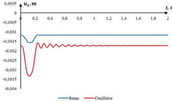
a)1×10⁸ N/m
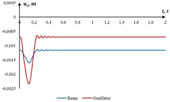
b)2.5×10⁸ N/m
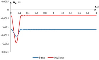
c)5×10⁸ N/m
On resonance phenomena: the superposition of these residual vibrations onto the forced vibrations can lead to a resonance amplification effect, which creates critical dynamic overloads in the structural members of the bridge. Therefore, to ensure the accuracy of calculations during high-speed operation and to maintain the dynamic stability of the system when selecting pitch and damping parameters, it is essential to take strict account of the wheelbase and the natural frequencies of the structure.
In the article [10], the critical velocity of the oscillator’s motion was estimated, which was 375.83 m/s (1353 km/h).
4. Conclusions
Main conclusions based on the calculation results:
1) The effect of oscillator stiffness on beam deflection: there is a regular decrease in vertical displacement of both the beam and the mass as spring stiffness increases from 1×10⁸ to 5×10⁸ N/m, which is related to the natural frequencies of the beam and oscillator.
2) Speed range 25-50 m/s: the vibrations are smooth, the damping coefficient has little effect on the maximum deflection amplitudes.
3) Speed range 50-100 m/s: the dynamics of the interaction between the oscillator and the beam begin to become apparent. Increasing to 0.002 s⁻1 effectively dampens the oscillations.
4) Further research will involve analysing the vibrations of the “rolling stock-bridge” system.
References
-
H. Xia and N. Zhang, Dynamic Analysis of Railway Bridges. Beijing: Science Press, 2011.
-
H. Xia and N. Zhang, “Dynamic analysis of railway bridge under high-speed trains,” Computers and Structures, Vol. 83, No. 23-24, pp. 1891–1901, Sep. 2005, https://doi.org/10.1016/j.compstruc.2005.02.014
-
W. Zhai, Z. Han, Z. Chen, L. Ling, and S. Zhu, “Train-track-bridge dynamic interaction: a state-of-the-art review,” Vehicle System Dynamics, Vol. 57, No. 7, pp. 984–1027, Jul. 2019, https://doi.org/10.1080/00423114.2019.1605085
-
K. Liu, G. de Roeck, and G. Lombaert, “The effect of dynamic train-bridge interaction on the fatigue life of railway bridges,” Journal of Sound and Vibration, Vol. 325, No. 1-2, pp. 210–226, 2009.
-
P. Antolín, N. Zhang, J. M. Goicolea, H. Xia, M. Astiz, and J. Oliva, “Consideration of nonlinear wheel-rail contact forces for dynamic vehicle-bridge interaction in high-speed railways,” Journal of Sound and Vibration, Vol. 332, No. 5, pp. 1231–1251, Mar. 2013, https://doi.org/10.1016/j.jsv.2012.10.022
-
L. Diachenko, A. Benin, and A. Diachenko, “Research of interaction of the “train – bridge” system with bridge deck resonant vibrations,” in MATEC Web of Conferences, Vol. 239, p. 05002, Nov. 2018, https://doi.org/10.1051/matecconf/201823905002
-
J. W. Kwark, E. S. Choi, Y. J. Kim, B. S. Kim, and S. I. Kim, “Dynamic behavior of two-span continuous concrete bridges under moving high-speed train,” Computers and Structures, Vol. 82, No. 4-5, pp. 463–474, Feb. 2004, https://doi.org/10.1016/s0045-7949(03)00054-3
-
Y. B. Yang, J. D. Yau, and Y. S. Wu, Vehicle-Bridge Interaction Dynamics: With Applications to High-Speed Railways. World Scientific, 2004.
-
M. Olsson, “On the fundamental moving load problem,” Journal of Sound and Vibration, Vol. 145, No. 2, pp. 299–307, Mar. 1991, https://doi.org/10.1016/0022-460x(91)90593-9
-
I. Mirzaev, D. S. Askarova, and S. S. Khojakhmatov, “Fluctuations of prestressed reinforced concrete railway bridge span during oscillator motion,” (in Russian), Bulletin of Siberian State University of Transport, No. 4, pp. 33–41, Dec. 2025, https://doi.org/10.52170/1815-9265_2025_76_33
-
I. Mirzaev, U. Shermukhamedov, A. Abdullaev, and D. Askarova, “Influence of seasonal temperature on the strength of continuous monolithic road overpasses,” in ICTEA: International Conference on Thermal Engineering, 2024.
About this article

The work was carried out under grant AL-8924063439 of the Agency for Innovative Development of the Ministry of Higher Education, Science and Innovations of the Republic of Uzbekistan.
The datasets generated during and/or analyzed during the current study are available from the corresponding author on reasonable request.
Prof. Ibrakhim Mirzaev is a scientific committee member of the 76th International Conference on Vibroengineering and was not involved in the editorial review and/or the decision to publish this article.
