Abstract
This paper investigates changes in the dynamic parameters and seismic response of reinforced concrete shell roofs of unique large-span buildings during long-term operation. The aim of the study is to evaluate how long-term loading, stiffness degradation, support rigidity, and boundary conditions affect the vibration characteristics and structural safety of shell systems subjected to high-intensity seismic actions. The research combines experimental modeling and theoretical analysis. Shell models and full-scale spatial structures were tested under long-term static loading and forced dynamic actions corresponding to design seismic intensities of 7, 8, and 9 points. The study considers free-standing and coupled conical domes, as well as shells of various geometric forms, with attention to oscillation modes, vibration periods, amplitudes, deflections, residual deformations, and crack development. The results show that long-term operation significantly reduces the dynamic rigidity of reinforced concrete shell systems and increases their deflections and residual deformations. A 5.86-fold increase in column rigidity increased the frequency of horizontal oscillations by 74.3 %, while the influence on vertical vibration frequencies remained limited. Long-term loading increased ultimate deflections by 1.5-2 times, fiber deformations by 2.4-2.75 times, and crack development by up to 2 times. A resolving system of equations for shell deformation under nonlinear creep conditions is proposed for assessing the stress-strain state of structures at the operational stage. The obtained results can be used to improve the seismic safety assessment and rational design of reinforced concrete shell roofs in seismic regions.
1. Introduction
Large-span reinforced concrete shell roofs remain one of the most efficient structural solutions for unique public and industrial buildings because they combine high spatial rigidity, favorable material distribution, and architectural expressiveness [1]-[3]. Interest in shell roofs has also persisted due to their structural efficiency and continued relevance in modern design practice, including renewed attention to thin shell and dome systems for contemporary long-span applications [11], [19], [20].
At the same time, the reliable use of such systems in seismic regions remains a challenging engineering problem. Shell structures are characterized by complex stress redistribution, strong sensitivity to boundary conditions, and nonlinear dynamic behavior under earthquake excitation. Their seismic resistance depends not only on the shell geometry itself, but also on the rigidity of supports, shell interaction within a coupled system, and the evolution of structural properties during operation [2], [14], [17], [18].
An additional difficulty arises at the operational stage. In real structures, long-term loading, creep, cracking, residual deformations, stiffness degradation, and the time-dependent evolution of concrete properties gradually change the dynamic characteristics of reinforced concrete shells [6], [13], [15], [16]. As a result, the natural frequencies, oscillation periods, amplitudes, and overall seismic response of the structure may differ substantially from those assumed at the design stage [6], [7], [15], [16]. For this reason, the assessment of shell roofs only under short-term or idealized conditions is insufficient for a reliable evaluation of structural safety and reliability, which requires more comprehensive assessment approaches for structures operating under complex service conditions [4], [6], [15], [16].
Previous studies have established the importance of nonlinear analysis, experimental verification, and improved numerical modeling for spatial systems and reinforced concrete shells, while broader modeling approaches for building systems under operational influences also confirm the relevance of computational assessment in structural engineering [2], [8], [9], [14], [17], [21]. However, insufficient attention has been paid to the combined assessment of shell roofs at the long-term operational stage under intense seismic actions, especially for free-standing and coupled dome-type systems with different support conditions and varying rigidity of the supporting elements [2], [5], [14]-[16].
This issue is particularly relevant for regions with high seismicity and demanding climatic conditions, where shell structures are required to maintain serviceability and safety over extended periods of operation [2], [5], [6], [10]. Under such conditions, the interaction between long-term material behavior and dynamic loading becomes a decisive factor in structural performance.
The aim of this paper is to investigate the dynamic parameters and seismic response of reinforced concrete shell roofs of unique buildings during long-term operation on the basis of experimental and theoretical studies. The study considers free-standing and coupled spatial shell systems subjected to high-intensity dynamic actions corresponding to severe seismic conditions. Special attention is given to the influence of loading duration, stiffness degradation, support rigidity, oscillation modes, and nonlinear creep on the stress-strain state and vibration characteristics of the structures.
The novelty of the study lies in the combined experimental and theoretical assessment of reinforced concrete shell roofs at the operational stage, taking into account changes in dynamic parameters caused by long-term loading, nonlinear creep, residual deformations, and seismic actions. Unlike studies focused mainly on design-stage behavior, the present work evaluates how the dynamic response of shell systems evolves after extended service under realistic operating conditions [14]-[17].
The main contribution of the paper is threefold. First, it provides experimental evidence on the vibration behavior of individual and coupled shell systems under vertical and horizontal dynamic actions. Second, it identifies the role of support rigidity and long-term degradation in changing the frequency characteristics and seismic response of shell roofs. Third, it presents a resolving system of equations for the assessment of shell deformation under nonlinear creep conditions, which can be used for a more reliable safety evaluation and rational design of large-span reinforced concrete shell structures in seismic regions.
The novelty of the study is as follows:
1) The seismic response of reinforced concrete shell roofs is assessed at the operational stage, rather than only at the design stage.
2) The study combines long-term loading effects, nonlinear creep, stiffness degradation, and dynamic seismic excitation within one assessment framework.
3) Both single and coupled dome systems are experimentally and theoretically compared.
4) The influence of support rigidity and spatial coupling on vibration characteristics is quantified.
2. Materials and methods
2.1. Investigated shell systems
Because of the complexity of reproducing the actual stress-strain state of large-span reinforced concrete shell roofs during long-term operation, the study combined theoretical analysis with experimental modeling. This integrated approach made it possible to assess the behavior of shell systems under conditions that are closer to real service life and subsequent seismic excitation.
The investigated structures included large-span reinforced concrete shell roofs of various geometric configurations intended for operation in seismic regions. Particular attention was paid to free-standing and coupled conical dome systems, since these configurations make it possible to evaluate the effect of shell interaction, support rigidity, and long-term degradation of stiffness on the dynamic response of the structure. The structural diagrams of the investigated systems are shown in Fig. 1.
Fig. 1Structural diagrams of the investigated large-span composite shell roofs of unique buildings
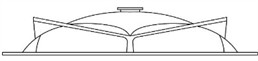
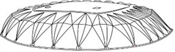

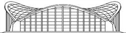
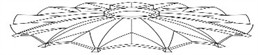
For the purposes of the present study, a single dome was considered as an individual shell-support system, whereas a coupled dome consisted of two adjacent shell units connected in the interaction zone by a spatial stiffness element. The purpose of this element was to ensure the joint operation of the shells and to increase the horizontal dynamic rigidity of the composite spatial system. The comparison of single and coupled domes made it possible to evaluate the influence of shell interaction and support conditions on the vibration characteristics and seismic response.
2.2. Geometry, support conditions, and excitation scheme
The tested shell systems included models and full-scale spatial structures with spans of 4.8, 12, 18, 24, 30, and 36 m, as well as free-standing and coupled multi-wave conical domes with spans of 18, 30, and 42 m. Depending on the specimen, the model scale varied from 1:4 to 1:10. For the detailed dynamic tests of coupled conical domes, a geometric scale of 1:5 was adopted.
The support arrangement and shell contour conditions used in the experimental setup were reproduced in the analytical formulation as boundary conditions. In the coupled system, compatibility of displacements and transfer of internal forces between adjacent shell units were ensured through the stiffness element located in the coupling zone. Such a representation made it possible to investigate the influence of both shell interaction and support rigidity on the dynamic characteristics of the structure.
Dynamic excitation was applied in both the vertical and horizontal directions. Vertical forced vibrations were generated by means of a frame fixed to the contour diaphragms of the shells, whereas horizontal excitation was introduced through the supporting columns and the loading frame of the test stand. The response of the structure was recorded in three orthogonal directions corresponding to the expected components of seismic action. The measured parameters included vibration frequencies, oscillation periods, amplitudes, deflections, residual deformations, and crack development.
2.3. Experimental program and loading regime
It is difficult to reproduce experimentally the complete long-term operational stress-strain state of reinforced concrete shell roofs while simultaneously controlling deflections, strains, residual deformations, and crack development. Therefore, shell models of the largest feasible dimensions were used after preliminary long-term static loading of different levels. This approach made it possible to simulate the operational stage more realistically and to reproduce the time-dependent changes in structural response caused by long-term loading.
The seismic resistance of large-size shell models that had been operated for up to seven years was assessed experimentally. The long-term stress-strain state at the time of testing was formed by overload stages with deflection control based on previously established nonlinear load-deflection relationships. The tests were carried out under laboratory conditions and included measurements of deformations and dynamic parameters in the selected design sections under free and forced vibrations, as well as under different combinations of static and dynamic loads.
Forced vibrations were generated using a V-2 vibration machine. To simulate earthquake action more realistically, the vibration machine tire was installed at the level of the power floor on special pads, which minimized energy losses during excitation. During the experiments, acceleration levels corresponding to seismic intensities of 7, 8, and 9 points were created, bringing the structure to a resonant state. Structural vibrations expected during an earthquake were recorded along the vertical and horizontal directions.
2.4. Theoretical formulation
To assess the stress-strain state of reinforced concrete shell roofs at the operational stage, a resolving system of equations for shell deformation under nonlinear creep conditions was formulated on the basis of the theory of flexible shallow shells with large deflections and established approaches to nonlinear analysis and concrete creep. In this formulation, the stress function, shell deflection function, stiffness-state parameters, and principal curvatures of the middle surface were introduced to describe the time-dependent deformation behavior of reinforced concrete shells during prolonged service [5], [6], [9]:
where, - are differential operators with variable stiffness coefficients, is the stress function, is the shell deflection function, and are parameters characterizing the stiffness state of the shell, and , are the principal curvatures of the middle surface. The adopted form of Eq. (1) reflects the influence of nonlinear creep and large deflections on the deformation behavior of reinforced concrete shells during long-term service.
After the governing relation for long-term deformation had been established, the seismic force corresponding to the selected vibration mode was represented through a modal expression that accounts for the distribution of inertial motion over the roof area, the building dimensions, vibration attenuation, and seismic-wave propagation. For circular spatial coverings, the same relation was written in polar coordinates:
The inertia of the system was introduced into the governing equations through an additional inertial-load term. Free vibrations of a bending-type shell were considered with allowance for physical and geometric nonlinearity, as well as creep effects. For composite shell systems, the governing equations were further transformed into a computational form suitable for determining the natural vibration frequencies and deformation characteristics of the investigated spatial structures:
For the determination of the natural vibration frequencies of composite spatial systems, the method of structural cuts was adopted. In this approach, instead of the original composite structure, several simpler shell components were considered. Along the cut lines, harmonically varying normal forces and moments with an unknown frequency were introduced. Forced-vibration problems were then solved for each shell component under the action of these boundary forces. By applying the equality of forces and deformation compatibility conditions in the shell-joint zones, the governing relation for determining the natural vibration frequencies of composite spatial structures was obtained [2], [5], [9]:
For elements of composite shells outlined along a single geometric surface, the equation was specified according to the adopted geometric shape and coordinate system. To solve free-vibration problems, the system of equations was transformed with respect to the unknowns used in the vibration analysis. For the solution of the free-vibration problem of composite shell systems, the governing relations were transformed into the following computational form:
2.5. Computational procedure
The numerical assessment was performed in four successive stages.
First, the long-term stress-strain state of the shell was determined by taking into account nonlinear creep, stiffness degradation, residual deformations, and the time-dependent evolution of material properties.
Second, the updated stiffness parameters of the shell-support system were introduced into the free-vibration equations in order to determine the dynamic characteristics of the structure at the operational stage rather than at the initial design stage.
Third, the natural frequencies, oscillation forms, and vibration periods of the investigated shell systems were determined for different structural configurations, including single and coupled domes, as well as for different support conditions and rigidity levels of the supporting elements.
Fourth, the modal seismic action corresponding to the selected vibration modes was introduced to evaluate the dynamic response of the shell roofs under high-intensity excitation. The theoretical predictions were then compared with the experimental observations in terms of vibration forms, frequencies, amplitudes, and deformation response.
Depending on the specimen, the shell contour was considered either clamped or simply supported, in accordance with the experimental setup.
2.6. Verification strategy
To verify the proposed approach, the natural vibration frequencies of experimentally studied long-term loaded shallow shells of positive and negative Gaussian curvature were evaluated for unique buildings with spans ranging from 18×18 m to 96×96 m and 120×190 m. Additional calculations were also carried out for domes with diameters up to 60 m, hanging roofs with spans up to 120 m, and structural systems with spans of 18-36 m.
Verification was performed by comparing the calculated and experimentally observed vibration characteristics of the investigated shell systems. The obtained agreement confirms that the adopted formulation adequately represents the dynamic behavior of reinforced concrete shell roofs during long-term operation.
3. Results and discussion
3.1. State of individual and coupled domes under dynamic impacts
The vertical and horizontal vibration modes of the shell models revealed a clear difference between the dynamic response of individual and coupled dome systems. At the initial stage of testing, the oscillation period during bending was small. During vertical oscillations caused by horizontal impacts, two principal vibration forms were identified. The higher mode corresponded to two symmetrical half-waves in the meridional direction along the shell surface. In the initial period of testing, high-tone oscillations with periods of 0.04-0.08 s were observed; later, they stabilized and corresponded to the lower tone of dome vibrations. Under different directions of horizontal impacts, the shell oscillations remained progressive and single-phase.
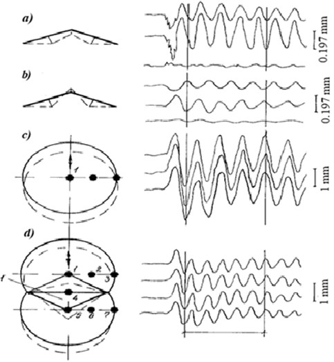
Fig. 2 clarifies the experimental and computational interpretation scheme used for the dynamic analysis of the tested conical dome models. It combines the structural configuration of the single and coupled dome systems, the direction of dynamic excitation, the location of measurement points, and the corresponding displacement-time histories. The tested dome models had spans of 18 and 30 m and were investigated at a geometric scale of 1:5. Panels (a) and (b) show the vertical response under horizontal excitation, while panels (c) and (d) illustrate the horizontal vibration modes of single and coupled dome systems. The circled numbers indicate the measurement points where oscillograms were recorded. The arrows indicate the direction of the applied dynamic impulse, and the dashed lines represent the deformed vibration shapes. The spatial stiffness element in the coupled dome system is denoted by I.
Fig. 2 shows that the vibration response of the tested dome models depends on the type of structural configuration and the direction of excitation. In the single dome, the recorded oscillograms demonstrate a more pronounced local response at the selected measurement points. In the coupled dome system, the spatial stiffness element provides joint operation of adjacent shells, which results in a more coordinated vibration pattern. The maximum vibration amplitude was observed in the middle part of the span of the meridional ribs, approximately at one quarter of the dome span from the lower support contour. The vibration amplitude in the middle of the dome span was approximately two times smaller than the maximum value. Under horizontal impacts, regardless of the distance and direction of the created dynamic impulse, the free-standing and coupled domes moved progressively in one phase and behaved as a single spatial rigid disk. For the coupled dome, the spatial stiffening element ensured joint operation under both horizontal and vertical impacts.
Fig. 2Experimental vibration modes, measurement scheme, and displacement-time histories of single and coupled conical dome models under dynamic excitation: a) single dome, vertical response under horizontal excitation; b) coupled domes, vertical response under horizontal excitation; c) single dome, horizontal vibration mode; d) coupled domes, horizontal vibration mode. Circled numbers indicate measurement points; arrows show the direction of dynamic impulse; dashed lines represent the deformed vibration shapes; I denotes the spatial stiffness element in the coupling zone. The displacement scales are 0.197 mm for panels a) and b), and 1.0 mm for panels c) and d); the time scale is 1.0 s
The experiments also showed that under both free and forced vibrations, the amplitude of horizontal vibrations was greater than that of vertical vibrations, because the rigidity of the shell in the vertical direction was significantly higher than in the horizontal direction. The direction of the forced vibrations of the structure coincided with the actual movement of the shell. During earthquakes, the oscillation of the spatial system follows a random law, whereas the shell itself transmits mainly those frequencies that are close to its own natural frequencies. Thus, the shell response retains an ordered harmonic character even under irregular external excitation.
In the horizontal direction, the shell works as a single spatial system. At the same time, the amplitude of the horizontal components depends strongly on the rigidity of the supporting structures. The use of conjugate shells ensures the combined operation of the columns and increases the dynamic rigidity of the composite shell in the horizontal direction. However, horizontal seismic effects are still perceived mainly by the supporting columns, while the shell elements themselves participate less effectively in resisting these actions. Therefore, increasing the rigidity of columns and adopting additional design measures remain important means of improving seismic resistance, which is also consistent with studies addressing the load-bearing assessment of reinforced concrete supporting elements [12].
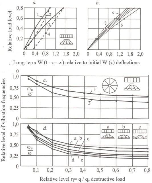
A particularly important result of the tests is the quantified influence of support rigidity. A 5.86-fold increase in column rigidity led to a 74.3 % increase in the frequency of horizontal oscillations of the conical dome under self-weight. As the load level increased, the effect of column rigidity on the frequency characteristics weakened. Thus, a four-fold increase in load reduced the influence of column rigidity on the oscillation frequency of the conical dome to 38.7 %. This indicates that under strong earthquakes the structure may approach its limit state and that the rigidity of the supporting columns remains one of the most important design parameters for shell systems of various geometric forms. By contrast, increasing column rigidity at different loading stages caused only a small increase in the frequencies of vertical vibrations, limited to about 5 %, which means that this effect may be neglected in practical design for the vertical vibration mode.
Fig. 3Graphs of changes in deflections and frequencies of vertical vibrations of shells depending on the loading level, loading duration, and boundary conditions: 1, 3 – short-term and long-term loading; 2, 4 – recovery after unloading; d, e – clamped and simply supported shell
3.2. Condition of long-term operated shell structures under dynamic impacts
Modeling the true stress-strain state of a structure while simultaneously reflecting both the construction and operation stages is extremely difficult. For this reason, the shell models were subjected to long-term tests lasting up to seven years. The experiments showed that the stress-strain state at the moment of loading undergoes considerable development over time due to the growth of long-term inelastic deformations, especially when temperature and humidity conditions are taken into account.
By the end of the observation period, the ultimate deflections of spatial shell structures of different geometric shapes had increased by 1.5-2.0 times compared with the initial loading stage. Fiber deformations increased by 2.4-2.75 times, and the observed crack widths or crack development increased by as much as 2 times. Residual deflections amounted to 23-60 %, while residual fiber deformations reached 35-80 %. These results indicate a significant reduction in the rigidity of reinforced concrete shell systems during long-term operation.
During the subsequent dynamic tests, the long-term stress-strain state of the shells was created by overload stages with deflection control using previously established nonlinear load-deflection relationships. The structure vibrations were again recorded in three orthogonal directions expected during seismic action. Forced vibrations in the vertical and horizontal directions were created by a vibration machine with acceleration levels corresponding to the estimated seismicity of 7, 8, and 9 points, bringing the structures to a resonant state. The tests involved both model and full-scale shell structures with spans of 4.8, 12, 18, 24, 30, and 36 m, as well as free-standing and coupled multi-wave conical domes with spans of 18, 30, and 42 m, using model scales from 1:4 to 1:10.
The results demonstrate that under strong seismic impacts, an increase in the magnitude of external loads and the duration of loading leads to a substantial decrease in dynamic rigidity, which is expressed experimentally by an increase in the period of the fundamental vibration tone. In other words, the shell becomes dynamically more flexible as a result of long-term loading and material degradation, which should be explicitly considered in the seismic safety assessment of structures at the operational stage.
3.3. Summary of key quantitative findings
The main experimentally observed changes in dynamic parameters and deformation characteristics of long-term operated reinforced concrete shell systems are summarized in Table 1.
The summarized results confirm that both support rigidity and long-term degradation must be explicitly considered in the seismic design and operational safety assessment of shell roofs.
Table 1Main experimentally observed changes in dynamic parameters and deformation characteristics of long-term operated reinforced concrete shell systems
No. | Parameter / response characteristic | Observed change | Engineering interpretation |
1 | Increase in horizontal vibration frequency due to 5.86-fold increase in column rigidity | 74.3 % | Support rigidity strongly affects the horizontal dynamic response |
2 | Influence of column rigidity on horizontal frequency under four-fold increase in load | 38.7 % | The effect of support rigidity decreases as the load level increases |
3 | Increase in vertical vibration frequencies due to increased column rigidity | Up to 5 % | The influence on vertical vibration modes is limited |
4 | Increase in ultimate deflections during long-term operation | 1.5-2.0 times | Long-term loading significantly reduces structural rigidity |
5 | Increase in fiber deformations during long-term operation | Factor of 2.4-2.75 | Time-dependent inelastic behavior strongly affects the stress-strain state |
6 | Increase in crack development during long-term operation | Up to 2 times | Damage accumulates during prolonged service life |
7 | Residual deflections after long-term loading | 23-60 % | Irreversible deformation remains substantial after unloading |
8 | Residual fiber deformations after long-term loading | 35-80 % | Long-term operation leads to significant irreversible strain accumulation |
4. Conclusions
This study investigated the dynamic parameters and seismic response of reinforced concrete shell roofs of unique buildings during long-term operation by combining experimental modeling and theoretical analysis. The obtained results lead to the following conclusions.
1) Long-term operation significantly changes the dynamic behavior of reinforced concrete shell systems, leading to reduced dynamic rigidity, increased deflections, residual deformations, and crack development.
2) The rigidity of supporting columns has a strong influence on the horizontal dynamic response of shell roofs. A 5.86-fold increase in column rigidity increased the frequency of horizontal oscillations by 74.3 %, whereas its influence on vertical vibration frequencies remained limited to about 5 %.
3) Long-term loading increased the ultimate deflections of shell structures by 1.5-2 times, fiber deformations by 2.4-2.75 times, and crack development by up to 2 times, confirming the importance of accounting for degradation effects at the operational stage.
4) A resolving system of equations for shell deformation under nonlinear creep conditions was formulated and used together with the free-vibration analysis framework to evaluate the stress-strain state and dynamic parameters of reinforced concrete shell systems.
5) The obtained results can be used for a more reliable seismic safety assessment and rational design of large-span reinforced concrete shell roofs operating in seismic regions.
References
-
V. V. Shugaev, B. S. Sokolov, and A. V. Pshenichnikov, “Calculation of precast reinforced concrete spatial roof structures,” (in Russian), in Concrete and Reinforced Concrete – a Look into the Future: Proc. III All-Russian (II International) Conf. on Concrete and Reinforced Concrete, pp. 414–425, 2014.
-
S. R. Razzakov, “Modeling of seismic resistance of spatial large-span unique structures in the operational stage,” IOP Conference Series: Materials Science and Engineering, Vol. 1079, No. 4, p. 042064, 2021, https://doi.org/10.1088/1757-899x/1079/4/042064
-
P. G. Eremeev, Modern Steel Structures of Long-Span Roofs of Unique Buildings and Structures. (in Russian), Moscow, Russia: ASV Publishing House, 2009, p. 336.
-
I. V. Lebedeva and T. A. Petrova, “Analysis of modern approaches to assessing reliability in construction,” (in Russian), Bulletin of Science and Research Center of Construction, Vol. 38, No. 3, pp. 20–36, 2023, https://doi.org/10.37538/2224-9494-2023-3(38)-20-36
-
N. S. Razzokov, Reinforced Concrete Shells for Unique Long-Span Buildings under Construction. (in Russian), Tashkent, Uzbekistan: Fan Publishing House of the Academy of Sciences of the Republic of Uzbekistan, 2022, p. 212.
-
A. G. Tamarazyan and S. G. Yesayan, Mechanics of Concrete Creep. (in Russian), 2012, p. 524.
-
V. N. Nekrestyanov, “Modeling of destruction of building structures,” (in Russian), Vestnik MGSU, No. 9, pp. 145–153, 2014.
-
E. Shipacheva, S. Shaumarov, A. Gulamov, and M. Talipov, “Modeling of interaction of external enclosing structures of buildings with the internal and external environments,” in ICTEA: International Conference on Thermal Engineering, Vol. 1, No. 1, 2024.
-
C. Meyer and K.-J. Bathe, “Nonlinear analysis of R/C structures in practice,” Journal of the Structural Division, Vol. 108, No. 7, pp. 1605–1622, 1982, https://doi.org/10.1061/jsdeag.0005991
-
“Minimum design loads for buildings and other structures,” Reston, VA, ASCE/SEI 7-02, Jan. 2003, https://doi.org/10.1061/9780784406243
-
P. P. Oleinik and V. I. Brodsky, Methods for Constructing Reinforced Concrete Domes. (in Russian), Moscow, Russia: ASV Publishing House, 2016, p. 232.
-
M. A. Gadzhiev and S. M. Alaeva, “Assessment of the accuracy of simplified diagrams of Euro standards in studying the load-bearing capacity of reinforced concrete columns,” (in Russian), Herald of the Azerbaijan Engineering Academy, Vol. 4, No. 1, pp. 65–79, 2012.
-
E. Shipacheva, S. Shaumarov, A. Gulamov, M. Talipov, and S. Kandakharov, “Water structure and its influence on cement stone and concrete properties,” in ICTEA: International Conference on Thermal Engineering, Vol. 1, No. 1, 2024.
-
T. Michiels and S. Adriaenssens, “Identification of key design parameters for earthquake resistance of reinforced concrete shell structures,” Engineering Structures, Vol. 153, pp. 411–420, Dec. 2017, https://doi.org/10.1016/j.engstruct.2017.10.043
-
E. Hamed, M. A. Bradford, and R. Ian Gilbert, “Nonlinear long-term behaviour of spherical shallow thin-walled concrete shells of revolution,” International Journal of Solids and Structures, Vol. 47, No. 2, pp. 204–215, 2010, https://doi.org/10.1016/j.ijsolstr.2009.09.027
-
E. Hamed, M. Bradford, and R. I. Gilbert, “Creep buckling of imperfect thin-walled shallow concrete domes,” Journal of Mechanics of Materials and Structures, Vol. 5, No. 1, pp. 107–128, 2010, https://doi.org/10.2140/jomms.2010.5.107
-
J. G. Teng and J. M. Rotter, “Geometrically and materially nonlinear analysis of reinforced concrete shells of revolution,” Computers and Structures, Vol. 42, No. 3, pp. 327–340, 1992, https://doi.org/10.1016/0045-7949(92)90029-y
-
P. D. Moncarz, M. Griffith, and P. Noakowski, “Collapse of a reinforced concrete dome in a wastewater treatment plant digester tank,” Journal of Performance of Constructed Facilities, Vol. 21, No. 1, pp. 4–12, 2007, https://doi.org/10.1061/(asce)0887-3828(2007)21:1(4)
-
A. Zingoni and N. Enoma, “Dual-purpose concrete domes: a strategy for the revival of thin concrete shell roofs,” Structures, Vol. 28, pp. 2686–2703, Dec. 2020, https://doi.org/10.1016/j.istruc.2020.10.067
-
A. Zingoni, “Stress and buckling resistance of dual-purpose concrete shells,” Thin-walled Structures, Vol. 170, p. 108596, 2022, https://doi.org/10.1016/j.tws.2021.108596
-
B. Harsono, F. M. Mahadiva, Tavio, M. Talipov, and H. Hermawan, “Pushover analysis of simple house structures in seismic zones,” in AIP Conference Proceedings, Vol. 3480, No. 1, p. 050035, Mar. 2026, https://doi.org/10.1063/5.0319164
About this article

The authors have not disclosed any funding.
The datasets generated during and/or analyzed during the current study are available from the corresponding author on reasonable request.
The authors declare that they have no conflict of interest.

