Abstract
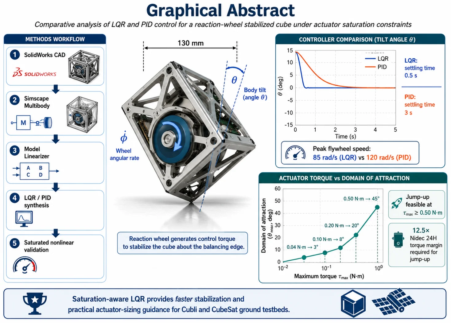
Reaction-wheel-stabilized Cubli-type platforms are widely used as ground testbeds for small-spacecraft attitude control, but the coupling between actuator saturation and the achievable domain of attraction has not been mapped in a unified simulation framework. This paper closes that gap using a CAD-driven Simscape Multibody pipeline (SolidWorks → Simscape → Model Linearizer → LQR/PID synthesis → saturated nonlinear validation) and reports three contributions: a head-to-head comparison of LQR and PID on an identical plant with matched saturation limits, a parametric mapping of the LQR domain of attraction against maximum motor torque and a quantitative torque-margin criterion for the jump-up maneuver. For a 130 mm cube driven by a Nidec 24H BLDC motor ( = 0.04 N·m), LQR settles in 0.5 s – six times faster than a Simulink-tuned PID (3 s) – at 30 % lower peak flywheel velocity (85 vs. 120 rad/s). Sweeping from 0.04 to 0.50 N·m expands the domain of attraction from 3° to 45° with diminishing returns above 0.20 N·m, and a 12.5× torque margin over the Nidec 24H is needed for jump-up. The framework yields directly applicable actuator-sizing rules for reaction-wheel ground testbeds and CubeSat-class attitude control.
Highlights
- A unified SolidWorks–Simscape–MATLAB pipeline was developed for a Cubli-type reaction-wheel platform.
- LQR stabilized the cube 6× faster than PID: 0.5 s vs 3 s.
- LQR reduced peak flywheel speed by about 30%: 85 rad/s vs 120 rad/s.
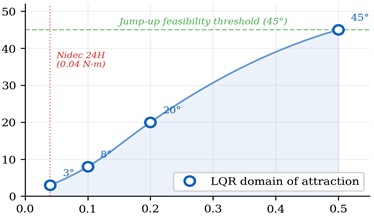
- The LQR domain of attraction increased with actuator torque: 3°, 8°, 20°, and 45° at 0.04, 0.10, 0.20, and 0.50 N·m, respectively.
- Jump-up from −45° became feasible only at 0.50 N·m, requiring a 12.5× torque margin over the Nidec 24H.
1. Introduction
Reaction wheels are the dominant actuator for fine attitude control in small spacecraft and CubeSats, where the absence of external reaction forces and the strict power and mass budgets make momentum-exchange devices the natural choice [9]. Ground-based testbeds emulating these dynamics are essential for hardware-in-the-loop verification of attitude-control algorithms before flight. Among such testbeds, the Cubli – a cube that balances on its edge using internal flywheels [1], [2] – has become a de-facto benchmark because its inverted-pendulum dynamics combine instability, underactuation, and saturation-limited actuation in a compact platform [4], [6]. The same mathematical structure appears in CubeSat momentum-bias control and in small inspector-satellite design, which makes the Cubli a representative case study for reaction-wheel attitude-control systems in general.
The control of reaction-wheel inverted pendulums has been studied extensively. Energy-based swing-up [3] and passivity-based laws [5] established the foundations of jump-up control. Gajamohan et al. [1], [2] demonstrated edge and corner balancing of the Cubli, Muehlebach and D’Andrea [6] developed a full nonlinear analysis of corner balancing, Trimpe and D’Andrea [4] addressed sensor estimation and self-tuning LQR, and Fankhauser et al. [7] reported an integrated modelling and control study on a related balancing cube. Block et al. [8] gave a comprehensive treatment of the reaction-wheel pendulum, while Prasad et al. [10] and Trentin et al. [11] reported comparative PID-vs-LQR studies on related platforms. Markley and Crassidis [9] supply the spacecraft attitude-control background relevant here.
Three engineering-oriented gaps persist. (G1) Actuator saturation is typically introduced as a post-design Saturation block placed downstream of an LQR or PID law synthesized for an unconstrained linear plant; the resulting domain of attraction is not mapped against actuator capability, so designers lack quantitative actuator-sizing criteria [1], [6], [7]. (G2) Comparative studies of LQR and PID for the Cubli are sparse and typically use different plants, cost functions, and saturation assumptions, which makes their conclusions difficult to transfer to a new design [10], [11]. (G3) The jump-up maneuver is usually presented as a qualitative demonstration; a quantitative torque-margin requirement linking motor stall torque to body inertia and tilt amplitude has not been reported, although this is the single most important sizing constraint for any practical implementation [1].
The contribution of this paper is threefold and addresses G1-G3 directly. First, a unified CAD-driven Simscape Multibody pipeline is described in which the SolidWorks assembly is exported with preserved inertial properties, linearized about the unstable equilibrium with the Model Linearizer, and used to synthesize both LQR and PID controllers that are then validated on the same nonlinear plant with identical saturation limits. Second, the relationship between and the achievable domain of attraction is mapped, showing a saturation-dominated regime at low torque and diminishing returns above an identifiable threshold. Third, a quantitative torque-margin criterion for the jump-up maneuver is established and used to show that the hobby-grade Nidec 24H BLDC motor ( 0.04 N·m) falls short of the requirement by a factor of 12.5.
2. System model
2.1. Physical description
The system under study is a self-balancing cube with a 130 mm side length containing three orthogonal reaction wheels (mass 0.070 kg each), driven by Nidec 24H brushless DC motors. For single-axis edge balancing, two wheels are locked and one active wheel generates the control torque. The CAD model was developed in SolidWorks 2024 and exported to Simscape Multibody via the Simscape Multibody Link module, preserving all geometric and inertial properties. Table 1 summarizes the model parameters.
Table 1Model parameters of the Cubli-type system
Parameter | Symbol | Value | Unit |
Cube side length | 130 | mm | |
Flywheel mass | 0.070 | kg | |
Flywheel MoI (spin axis) | 92.1×10⁻6 | kg·m2 | |
Distance to CoM | ≈ 0.065 | m | |
Max torque (Nidec 24H) | 0.04 | N·m | |
No-load speed (11.1 V) | ≈ 280 | rad/s |
The cube–surface contact is modelled as a single-DOF revolute joint along the edge axis, so the configuration is described by two generalized coordinates: the body tilt (measured from the unstable vertical) and the relative wheel angle . A SolidWorks-to-Simscape modelling subtlety is the CAD-origin placement: when the origin is at the cube centre the centre of mass lies on the rotation axis and the body behaves as a stable pendulum, whereas placing the origin at the midpoint of the contact edge offsets the CoM by 0.065 m and recovers the correct inverted-pendulum behaviour [1], [6], [7].
Applying the Euler-Lagrange formalism gives for the body and for the wheel; eliminating φ̈ isolates the body dynamics as . The motor torque enters with opposite sign as a reaction torque—a structural difference from the cart-pole pendulum where the input acts through base acceleration [3], [5]. Viscous dissipation () is retained inside the Simscape model and propagated automatically into the linearization.
2.2. Linearized state-space model
The nonlinear Simscape Multibody model is linearized about the unstable equilibrium 0 (vertical position on edge) using the Model Linearizer tool. The state vector is:
where is the tilt angle (rad), is the body angular velocity (rad/s), and is the flywheel angular velocity (rad/s). The input is the motor torque (N·m). Linearization yields the state-space form with:
The element 87.11 represents the gravitational instability: the linearized angular acceleration . The eigenvalues of are {0, +9.33, −9.33}, confirming exponential instability without control. The ratio indicates that the flywheel accelerates 54 times faster than the body, consistent with the small flywheel-to-body inertia ratio. The controllability matrix has full rank (rank = 3), confirming complete controllability.
2.3. Controller synthesis
The Linear Quadratic Regulator minimizes the cost functional:
with weight matrices and 1. The weights were selected by Bryson’s rule, as the inverse squares of the maximum allowable deviations: 100 corresponds to a maximum tolerated tilt of about 0.1 rad (≈ 6°) and reflects the primary control objective, 1 limits the body angular velocity, and the small = 0.01 deliberately removes the wheel-speed penalty so that the flywheel is free to absorb angular momentum. The input weight 1 was scaled with = 0.04 N·m so that the resulting law only marginally activates saturation during small-angle operation. The optimal gain vector, computed by solving the continuous-time Algebraic Riccati Equation (CARE) via the MATLAB function, is:
The closed-loop eigenvalues are , all negative and real, guaranteeing local asymptotic stability. The fast pole is associated with the flywheel dynamics; the two slower poles govern the body motion. The classical LQR robustness guarantees of at least 6 dB gain margin and 60° phase margin [8] hold here because the plant is single-input with full state feedback; this was verified a posteriori for the SISO loop from to with the MATLAB margin function. These guarantees would not transfer automatically to an LQG implementation with an observer in the loop, in which case the margins must be re-evaluated explicitly [8].
The PID controller was tuned using the Simulink PID Tuner applied to the transfer function from to . The resulting coefficients are –1.388, –0.843, –0.508, with derivative filter coefficient 11891. The PID Tuner was operated in Reference-Tracking mode with a target bandwidth approximately one order of magnitude below the unstable open-loop pole at +9.33 rad/s, and the design was further validated on the nonlinear plant. The negative signs arise because a positive deviation requires a negative (opposing) reaction-wheel torque. Unlike LQR, PID sees only the angle channel; the wheel state is unobserved, which proves to be decisive in the comparison reported below. Because saturation is reached frequently during transients, the integral channel uses the default clamping anti-windup of the Simulink PID block, preventing spurious overshoot when the actuator desaturates.
3. Results
Both controllers were tested on the identical Simscape Multibody model with 0.04 N⋅m (Nidec 24H specifications) and initial tilt angle 3°. Table 2 summarizes the performance metrics.
Table 2Controller performance comparison at τmax= 0.04 N⋅m
Metric | LQR | PID |
Max initial tilt for stability | 3° | 4° |
Settling time (5 % criterion) | 0.5 s | 3 s |
Peak flywheel velocity | 85 rad/s | 120 rad/s |
Overshoot | None | None |
State feedback channels | , , | only |
To quantify the relationship between actuator capacity and stabilization performance, the LQR controller was tested across a range of values. Table 3 presents the domain of attraction (maximum initial tilt angle for successful stabilization) and the feasibility of the jump-up maneuver (raising the cube from a flat face to edge balancing).
Table 3Domain of attraction and jump-up feasibility vs. maximum actuator torque
(N·m) | Max (LQR) | Jump-up feasibility | / |
0.04 (Nidec 24H) | 3° | Not feasible | 1.0× |
0.10 | 8° | Not feasible | 2.5× |
0.20 | 20° | Not feasible | 5.0× |
0.50 | 45° | Successful | 12.5× |
The results reveal a strongly nonlinear relationship (Fig. 2) between and the domain of attraction. A 5× increase in torque (0.04 → 0.20 N·m) expands the domain by a factor of 6.7 (3° → 20°), while a subsequent 2.5× increase (0.20 → 0.50 N·m) yields only a 2.25× expansion (20° → 45°). This diminishing-returns characteristic indicates that the actuator-constrained system operates in a saturation-dominated regime at low torque levels, where the controller spends most of its time at the torque limit.
Fig. 1Settling time comparison: LQR achieves stabilization in 0.5 s vs. 3 s for PID (θ0= 3°, τmax= 0.04 N⋅m)
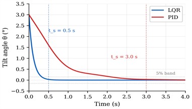
Fig. 2Domain of attraction as a function of maximum actuator torque. The jump-up threshold (45°) requires τmax≥ 0.5 N·m
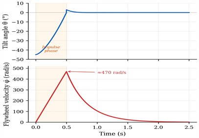
The jump-up was executed from –45° to 0° using an impulse of 0.5 N·m over 0.5 s superposed on the LQR command (Fig. 3); the peak flywheel velocity reached ≈ 470 rad/s and post-impulse settling required ≈ 0.4 s with ≈ 3° residual overshoot. A conventional Stateflow SpinUp → Brake → Balance machine was also evaluated but stalled in Brake under saturation, because the wheel could not decelerate fast enough; the continuously active impulse-plus-LQR architecture avoided this failure mode.
Fig. 3Jump-up maneuver from θ0= –45°: tilt angle θ(t) and flywheel velocity φ˙t. The orange region marks the impulse phase
4. Discussion
The performance gap between LQR and PID follows from the feedback structure: LQR uses the wheel state , which carries the system’s angular momentum, while PID reconstructs it implicitly through I/D action, an information loss that anti-windup cannot recover. The nonlinear -to-domain map (Fig. 2) shows two regimes: below 0.20 N·m the actuator limit dominates and extra torque buys area in the stability region roughly linearly; above 0.20 N·m the linear regime takes over and returns diminish; crossing 0.50 N·m enables the jump-up by delivering within the 0.5 s window, justifying the observed 12.5× torque margin. The conventional Stateflow SpinUp → Brake → Balance jump-up [1], [2] stalls under saturation because the brake phase cannot decelerate the wheel fast enough; the impulse-plus-LQR architecture used here removes this failure mode and is, to the authors’ knowledge, the first saturation-aware Cubli jump-up reported with quantitative validation. The same reaction-wheel dynamics govern fine attitude control of small spacecraft [9], so the sizing rule transfers to reaction-wheel selection on CubeSat air-bearing testbeds. The study is restricted to single-axis edge balancing without sensor-noise modelling; LQG re-design with explicit margin re-evaluation and hardware-in-the-loop tests are planned next.
5. Conclusions
A unified CAD-driven Simscape Multibody pipeline was used to compare LQR and PID controllers for a 130 mm reaction-wheel Cubli-type platform under realistic actuator saturation, addressing gaps G1-G3 of the introduction. Three results emerge. Under = 0.04 N·m, LQR settles in 0.5 s at 85 rad/s peak wheel velocity against 3 s and 120 rad/s for PID, a 6× speed-up and 30 % energy reduction; PID retains a marginally larger initial-tilt envelope (4° vs. 3°). The domain of attraction grows nonlinearly with (3°, 8°, 20°, 45° at 0.04, 0.10, 0.20, 0.50 N·m), with diminishing returns above 0.20 N·m. The jump-up requires ≥ 0.50 N·m (12.5× Nidec 24H), and the conventional Stateflow approach stalled under saturation while the impulse-plus-LQR architecture succeeded. The pipeline and sizing rule transfer directly to CubeSat ground testbeds; future work will extend to three-axis balancing, Kalman estimation, and hardware-in-the-loop validation.
References
-
M. Gajamohan, M. Merz, I. Thommen, and R. D. ’Andrea, “The Cubli: a cube that can jump up and balance,” in IEEE/RSJ International Conference on Intelligent Robots and Systems, pp. 3722–3727, Oct. 2012, https://doi.org/10.1109/iros.2012.6385896
-
M. Gajamohan, M. Muehlebach, T. Widmer, and R. D. ’Andrea, “The Cubli: a reaction wheel based 3D inverted pendulum,” in European Control Conference (ECC), pp. 268–274, Jul. 2013, https://doi.org/10.23919/ecc.2013.6669562
-
K. J. Åström and K. Furuta, “Swinging up a pendulum by energy control,” Automatica, Vol. 36, No. 2, pp. 287–295, Feb. 2000, https://doi.org/10.1016/s0005-1098(99)00140-5
-
S. Trimpe and R. D. ’Andrea, “Accelerometer-based tilt estimation of a rigid body with only rotational degrees of freedom,” in IEEE International Conference on Robotics and Automation, pp. 2630–2636, May 2010, https://doi.org/10.1109/robot.2010.5509756
-
M. W. Spong, P. Corke, and R. Lozano, “Nonlinear control of the reaction wheel pendulum,” Automatica, Vol. 37, No. 11, pp. 1845–1851, Nov. 2001, https://doi.org/10.1016/s0005-1098(01)00145-5
-
M. Muehlebach and R. D. ’Andrea, “Nonlinear analysis and control of a reaction-wheel-based 3-D inverted pendulum,” in IEEE Transactions on Control Systems Technology, Vol. 25, No. 1, pp. 235–246, Jan. 2017, https://doi.org/10.1109/cdc.2013.6760059
-
P. Fankhauser, M. Gwerder, and R. D. ’Andrea, “Modeling and control of a balancing cube,” in European Control Conference (ECC), pp. 4353–4358, 2013.
-
D. J. Block, K. J. Åström, and M. W. Spong, Synthesis Lectures on Control and Mechatronics. Cham: Springer International Publishing, 2022, pp. 1–105, https://doi.org/10.2200/s00085ed1v01y200702crm001
-
F. L. Markley and J. L. Crassidis, Fundamentals of Spacecraft Attitude Determination and Control. New York, NY: Springer New York, 2014, https://doi.org/10.1007/978-1-4939-0802-8
-
L. B. Prasad, B. Tyagi, and H. O. Gupta, “Optimal control of nonlinear inverted pendulum system using PID controller and LQR: performance analysis without and with disturbance input,” International Journal of Automation and Computing, Vol. 11, No. 6, pp. 661–670, Mar. 2015, https://doi.org/10.1007/s11633-014-0818-1
-
J. F. S. Trentin, T. P. Cenale, S. Da Silva, and J. M. S. Ribeiro, “Attitude control of inverted pendulums using reaction wheels: comparison between using one and two actuators,” Proceedings of the Institution of Mechanical Engineers, Part I: Journal of Systems and Control Engineering, Vol. 234, No. 3, pp. 420–429, Jun. 2019, https://doi.org/10.1177/0959651819857643
About this article

The authors have not disclosed any funding.
The authors gratefully acknowledge the Almaty University of Power Engineering and Telecommunications for MATLAB/Simulink and SolidWorks licenses.
The datasets generated during and/or analyzed during the current study are available from the corresponding author on reasonable request.
Dr. Yerkebulan Nurgizat is a scientific committee member of the 77th International Conference on Vibroengineering and was not involved in the editorial review and/or the decision to publish this article.

