Abstract
This paper presents an experimental and analytical study of the erection state of large-span reinforced concrete shell structures for unique buildings. The research focuses on the stress-strain behavior of shell systems during installation, dismantling of temporary erection devices, and transition to the operational stage. Experimental modeling was carried out on large-scale models with scales of 1:10 and 1:4 for shells with spans of 48 m, 96 m, and more. Composite shells assembled from prefabricated and enlarged erection elements were investigated for different erection and dismantling sequences. The stress-strain state was evaluated under self-weight and installation loads, and the obtained results were compared with calculation data based on shell theory relations and engineering modeling procedures. It was established that the most rational dismantling sequence consists in first lowering the temporary posts and beams and then removing the forces in the temporary ties. This sequence reduces the forces in the ties by 21-34 % and ensures a more favorable stress state of the shell elements. For the studied shell configurations, labor costs were reduced by 26 %, while the weight of the erection equipment set was reduced by 2.4 times compared with traditional assembly methods. The discrepancy between experimental and calculated ultimate forces did not exceed 8.8 %. The proposed approach can be used in the design and construction practice of unique large-span buildings to improve erection safety, structural efficiency, and reliability.
1. Introduction
Large-span spatial structures occupy a special place in the design of unique buildings because they make it possible to cover extensive areas while maintaining structural efficiency, architectural expressiveness, and material economy [1]-[3]. Among the available structural solutions, reinforced concrete shell systems remain one of the most promising options for unique buildings due to their favorable stiffness, load-bearing capacity, and geometric adaptability [2], [5]. The practical use of such shell structures is closely related not only to their behavior under service loads, but also to their performance during erection, dismantling of temporary devices, and transition to the operational stage [4], [6], [7].
A considerable number of studies have addressed the mechanics, design, and reliability of shell structures, including nonlinear analysis, optimal design, and staged structural behavior [3], [8], [11], [12]. At the same time, large-span unique buildings require special attention because their structural safety depends strongly on the erection sequence, temporary support conditions, and redistribution of forces during intermediate construction stages [5], [7], [10]. In addition, large-span structural systems are often considered in relation to seismic safety and nonlinear structural response, which further highlights the importance of comprehensive stage-by-stage assessment [9], [13].
In engineering practice, reinforced concrete shell coverings may be erected using solid scaffolding, sparse temporary supports, or enlarged prefabricated erection elements. For shells with moderate spans, erection using enlarged elements may be sufficient, whereas for spans of 60-100 m and more, combined erection methods become necessary. In such cases, the arrangement of temporary beams and ties, the choice of installation sequence, and the order of dismantling operations directly affect deflections, stress redistribution, and the general reliability of the shell system [5], [6], [7]. Related mathematical modeling approaches have also been applied to building structural systems and enclosing structures, confirming the importance of rational modeling strategies for complex engineering configurations [14].
Despite the progress achieved in the design and analysis of shell systems, the erection state of large-span reinforced concrete shells remains insufficiently clarified. In particular, the stress-strain state of shell structures during erection and dismantling may differ substantially from their behavior in the operational stage, which means that an assessment based only on service conditions may lead to underestimated structural effects. Therefore, the study of erection-stage behavior, temporary support systems, and rational dismantling procedures is an important task for the design and construction of unique buildings [5], [7], [10].
The aim of this study is to assess the stress-strain state of large-span reinforced concrete shell structures during erection and transition to the operational stage, and to identify rational structural and technological solutions for their assembly and dismantling. The research includes experimental modeling of shell systems with spans of 48 m, 96 m, and more, as well as comparative analysis of alternative erection and dismantling sequences [5], [7].
The novelty of the present work lies in the combined experimental and analytical assessment of the erection state of composite large-span shell structures assembled from enlarged elements, with particular attention to the sequence of dismantling temporary supports and ties. Unlike approaches focused mainly on operational conditions, the proposed methodology makes it possible to evaluate the shell behavior at installation and transition stages and to identify the most rational erection procedure from the viewpoints of structural safety, stress redistribution, labor efficiency, and reliability.
To achieve this objective, large-scale shell models were studied under self-weight and erection loads, the corresponding stress-strain state was evaluated, and the results were compared with engineering calculations based on shell theory relations. On this basis, recommendations are proposed for the design and erection of unique large-span buildings with reinforced concrete shell coverings.
2. Materials and methods
2.1. Structural schemes and research concept
The study focuses on the erection state of large-span reinforced concrete shell structures used in unique buildings. The assessment includes the installation stage, the release of temporary erection devices, and the transition of the structure to the operational stage. Particular attention is paid to the stress-strain state, deflections, internal forces, and structural safety during intermediate construction stages, since these parameters may differ significantly from those observed under service conditions.
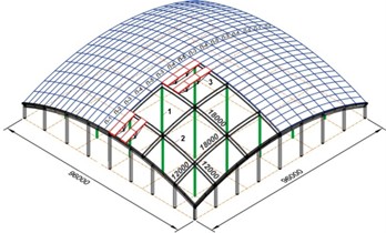
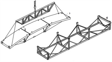
The investigated structural systems are shallow reinforced concrete shells assembled from prefabricated and enlarged erection elements. The considered design solutions include shells with spans of 48 m, 96 m, and more, as well as shell coverings erected using solid scaffolding with sparse supports and enlarged mounting elements. The structural schemes of the investigated shells are shown in Fig. 1, while the principal erection stages and the arrangement of temporary supports and enlarged mounting elements are presented in Fig. 2.
Fig. 1Structural schemes of shallow reinforced concrete shells
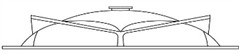

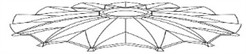
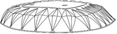
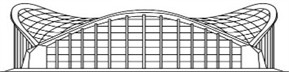
Fig. 2Erection stages of large-span shell coverings using enlarged mounting elements: 1 – temporary posts; 2 – cross stiffening beams; 3 – enlarged mounting elements; 4 – assembly stand
2.2. Experimental models and erection procedures
To develop a rational method for erecting composite reinforced concrete shells, experimental modeling of erection states was carried out on models with scales of 1:10 and 1:4, manufactured from fine-grained and heavy concrete. The shells were assembled using a combined erection method based on prefabricated and enlarged elements with dimensions from 3×18 m to 3×36 m with a 6 m gradation, together with their scaled models of 0.75×8.5 m and 0.3×1.8 m.
The stress-strain state of the shell covering was studied under a uniformly distributed load of 1.7 kN/m2, corresponding to self-weight and erection loading. The erection sequences and their influence on the structural behavior of the entire shell covering were investigated. Two principal dismantling procedures were considered:
1) first lowering the temporary posts and mounting beams, and then removing the forces in the temporary ties;
2) first removing the forces in the temporary ties, and then lowering the temporary posts and mounting beams.
Each dismantling variant was repeated three times. The comparative analysis of these procedures made it possible to assess the influence of the erection sequence on deflections, force redistribution, and the general reliability of the shell system.
The 1:10-scale models were manufactured from fine-grained concrete with a cubic compressive strength of approximately 25 MPa and a modulus of elasticity of about 26 GPa, whereas the 1:4-scale models and the full-scale erection elements were made of heavy concrete of class B25 with a corresponding modulus of elasticity of about 30 GPa. The shells were reinforced with welded wire meshes and individual bars of class A400 (yield strength of about 400 MPa); the diameter and spacing of the reinforcement were chosen from similarity conditions, with bars of 1.0-2.0 mm for 1:10 models, 3.0-6.0 mm for 1:4 models, and 8.0-12.0 mm for full-scale elements. Geometric and mechanical similarity between the models and the prototype shells was maintained to ensure correct scaling of the stress-strain state. The shell thickness was 60 mm for the full-scale elements and was scaled proportionally for the reduced-scale models.
The measurement program included resistance strain gauges with a base length of 5-20 mm installed on the upper and lower surfaces of the shell panels, on the ribs, contour diaphragms, and tightening trusses; mechanical and electronic dial indicators with a resolution of 0.01 mm for vertical deflections; and horizontal displacement transducers placed at the supports and along the contour structures. The locations of the gauges were chosen so as to capture both the membrane and bending response of the shell. Readings were recorded after stabilization at each loading and dismantling step, and each measurement was averaged over three repeated tests.
The loading procedure was performed in successive steps. The self-weight load of 1.7 kN/m2 was applied as a system of equivalent calibrated point loads uniformly distributed over the shell surface; the destructive load of 2.4 kN/m2 was applied as an upper bound for evaluating the safety margin. Each loading increment was held until stabilization of the readings (change in deflection below 5 % within 5-10 minutes) before the next step was applied. The boundary conditions of the shell models reproduced those of the prototype: during the erection stage the shells rested on contour arched diaphragms supported by temporary posts and mounting beams, while in the operational stage the contour diaphragms were transferred to permanent supporting columns. Tangential displacements along the supported edges were restrained, whereas rotations were allowed, in agreement with the assumed support conditions of the shallow shell formulation. The dismantling operations were carried out in calibrated steps, so that the redistribution of forces in the temporary ties, posts, and beams could be tracked separately at each stage.
2.3. Analytical formulation
To interpret the experimental data and evaluate the stress-strain state of the shell structures, the governing relations of the nonlinear theory of shallow shells were used. Based on the general equations of the moment theory of thin shells, the following resolving equation of the nonlinear theory was adopted:
where is the cylindrical rigidity of the shell, is the Laplace operator, is the Vlasov operator, is the deflection function, is the stress function, and denotes a nonlinear operator.
After the corresponding transformations, the compatibility equation expressed through the force and deflection functions can be written as:
where is the modulus of elasticity and is the shell thickness. Thus, the study of the stress-strain state according to the nonlinear theory of shallow shells in mixed form is reduced to the joint integration of two nonlinear differential equations:
These equations contain two unknown nonlinear functions, and , and are considered together with the corresponding boundary conditions at the shell edges.
In Eqs. (1-3) the following notation is adopted: is the cylindrical (bending) rigidity of the shell, where is the modulus of elasticity of the shell material, is the shell thickness, and is Poisson’s ratio; is the Laplace operator in the rectangular coordinate system attached to the shell mid-surface; is the Vlasov operator, in which and are the principal curvatures of the shell along the - and -axes; is the deflection of the shell mid-surface measured along the normal direction; is the Airy-type stress function, from which the membrane forces are obtained as , , ; is the surface load normal to the shell mid-surface, taken in the present study as 1.7 kN/m2 for self-weight loading and 2.4 kN/m2 for destructive loading; and and are nonlinear bracket operators that account for the coupling between deflections and membrane forces in the shallow shell formulation. The boundary conditions correspond to shells supported on contour diaphragms: tangential displacements along the supported edges are restrained, while normal rotations are unrestricted.
In Eqs. (4-6) the additional notation is as follows: and ( 1, 2) are the membrane normal and shear forces in the i-th direction of the shell mid-surface; and are the bending and twisting moments; , , and are the tangential, transverse, and normal displacements of the shell mid-surface; is a characteristic linear dimension of the shell (taken equal to the shell span); and on the right-hand sides denote dimensionless geometric coefficients depending on the shell curvature and aspect ratio; and the bar over a quantity denotes its dimensionless coefficient. The dimensionless coefficients were evaluated for each loading level and for each control point of the nonlinearly deformable shell panel and were used for the comparative assessment of experimental and calculated results.
2.4. Evaluation of forces and displacements
For engineering calculations and comparative assessment of the investigated shell systems, analogous tabular and computational procedures were used. The membrane forces were determined from:
The moment forces from:
The displacements from:
Here, the dimensionless coefficients of forces and displacements were determined for each type and level of load at the investigated points of the nonlinearly deformable shell panel. These coefficients were then used for the comparative assessment of the experimental and calculated response of the shell system.
2.5. Comparative evaluation of experimental and calculated results
A comparative analysis of experimental and calculated data was carried out for an erection element measuring 3×18 m in full scale and for its models with scales 1:1, 1:4, and 1:10 under standard erection load, self-weight load of 1.7 kN/m2, and destructive load of 2.4 kN/m2. The comparison of the full-scale erection element and its models showed that the experimental and calculated ultimate forces in the tightening truss were 330.8 kN and 301.7 kN, respectively. The discrepancy between the two sets of results was 8.8 % and 7.5 %, which confirms the applicability of the adopted modeling and calculation approach.
The obtained methodology was further used to assess the behavior of shell coverings of various geometric configurations for unique large-span buildings with spans of 48-96 m and more. This made it possible to evaluate the feasibility of using the proposed erection procedure and analytical approach in design and construction practice.
Table 1Main parameters of the experimental program
Parameter | Value / description |
Structural type | Reinforced concrete shallow shell |
Investigated spans | 48 m, 96 m and more |
Model scales | 1:10, 1:4, and full-scale comparison |
Erection element dimensions | 3×18 m to 3×36 m |
Model element dimensions | 0.75×8.5 m and 0.3×1.8 m |
Main distributed load | 1.7 kN/m² |
Destructive load | 2.4 kN/m² |
Dismantling procedure 1 | First lower posts and beams, then remove tie forces |
Dismantling procedure 2 | First remove tie forces, then lower posts and beams |
Number of repeated dismantling variants | 3 |
3. Results and discussion
3.1. Experimental assessment of the erection state
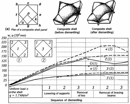
At the first stage of the experimental study, the stress-strain state of separately standing central shells and lateral shells of negative and positive Gaussian curvature was investigated under a uniformly distributed load corresponding to the self-weight of the structure, equal to 1.7 kN/m2. After loading, two principal dismantling procedures were analyzed, and the change in the stress-strain state was evaluated at each stage of the release of temporary erection devices.
The results showed that, in the first dismantling procedure, lowering the temporary posts and mounting beams before releasing the forces in the temporary ties reduced the initial forces in the ties by 21-34 %, which significantly facilitated their removal. In this case, a more favorable stress state was observed in the ribs of the shell panels. When the temporary posts and beams were lowered, the maximum deflection of the central shell was 2.9 mm, which corresponds to 1/1155 of the span, whereas for the lateral shell the maximum deflection was 1.9 mm, or 1/1786 of the span. Subsequent release of forces in the temporary ties increased the initial deflections of the central and lateral shells by 1.2 and 1.15 times, respectively.
Fig. 3Deflection changes in a composite shell (4.8×4.8 m) during erection and dismantling: a) displacement development under erection loading and release of temporary erection devices; b), c) deflections of the middle diaphragms along the lines of temporary ties and mounting beams
Thus, the first dismantling procedure, in which the temporary posts and beams are lowered before the release of forces in the ties, should be considered the most rational. A similar tendency was observed for horizontal displacements of the shell, which decreased by 1.14-1.30 times for different sides of the contour structures of the lateral shells. In addition, the lowest values of longitudinal forces and bending moments were obtained for this dismantling sequence, which confirms its structural advantage.
At the second stage of the study, the stress-strain state of a monolithically connected system consisting of the central shell and four lateral shells of negative and positive Gaussian curvature, installed on four common arched diaphragms and loaded by self-weight of 1.7 kN/m2, was investigated. A comparative analysis of two dismantling procedures showed that the first procedure again provided more favorable structural behavior. In particular, the deflections at the mid-span of the shell and diaphragm were smaller by 1.65 and 1.4 times, respectively, compared with the second procedure. A similar effect was observed for horizontal displacements, which decreased by 1.15-1.27 times for different sides of the contour structures of the lateral shell elements. The lowest longitudinal forces and bending moments were also obtained for the first procedure, which confirms the feasibility of its practical use.
3.2. Analytical and comparative evaluation
To interpret the behavior of the shell structures, the stress-strain state was also assessed using the adopted nonlinear shell formulation and engineering calculation procedures. The use of direct analytical expressions for nonlinear shell behavior is labor-intensive even for simplified problems; therefore, analogous computational procedures and tabular evaluation methods were applied for engineering comparison of forces and displacements. On this basis, the shell behavior was assessed for different geometric schemes, loading levels, and erection sequences.
A comparative analysis of the full-scale erection element and its models was carried out for a 3×18 m shell element under a standard erection load, self-weight load of 1.7 kN/m2, and destructive load of 2.4 kN/m2. The comparison showed that the experimental and calculated ultimate forces in the tightening truss were 330.8 kN and 301.7 kN, respectively. The discrepancy between the experimental and calculated data was 8.8 % and 7.5 %, which confirms that the adopted methodology provides an acceptable level of accuracy for engineering analysis of erection-stage shell behavior.
The obtained results demonstrate that the stress-strain state of spatial shell systems should not be assessed only for the operational stage. If erection conditions and the sequence of dismantling temporary devices are neglected, the resulting structural assessment may be underestimated. The present study therefore confirms the necessity of considering erection-stage effects when designing large-span shell coverings for unique buildings. The numerical and experimental results indicate that the proposed methodology can be used for the practical design and erection of shell structures with spans of 48-96 m and more.
Compared with the traditional erection technologies based on solid scaffolding over the full footprint or on full-coverage temporary trusses, the proposed sequence improves structural safety on several measurable counts. First, the reduction of forces in the temporary ties by 21-34 % prior to their release eliminates the risk of a sudden, uncontrolled stress redistribution that would otherwise occur when a heavily loaded tie is cut: in the traditional sequence the tie is removed while still carrying its maximum tensile force, producing a step-like force jump in the adjacent shell ribs and contour diaphragms, whereas in the proposed sequence the ties are unloaded gradually as the posts and beams are lowered. Second, the reduction of mid-span deflections by 1.65 and 1.4 times for the shell and diaphragm, together with the 1.15-1.27 times reduction of horizontal displacements, shows that the shell enters its self-supporting state under a smaller initial perturbation; this decreases the probability of local buckling, cracking, and overloading of the contour structures during the transition from erection to operational conditions. Third, the 26 % reduction of labor costs and the 2.4 times reduction of the erection-equipment weight shorten the duration of work at height and reduce the number of crane operations, which are recognized risk factors in the construction of large-span coverings. Together, these effects confirm that the proposed dismantling sequence is not only structurally more efficient but also safer than traditional erection technologies for shells with spans of 48-96 m and more.
Table 2Key comparative results of the experimental and analytical assessment
Parameter | Result |
Distributed self-weight load | 1.7 kN/m2 |
Destructive load | 2.4 kN/m2 |
Reduction of forces in temporary ties after lowering posts and beams | 21-34 % |
Maximum deflection of central shell | 2.9 mm |
Maximum deflection of lateral shell | 1.9 mm |
Increase in central shell deflection after tie-force release | 1.2 times |
Increase in lateral shell deflection after tie-force release | 1.15 times |
Reduction of shell mid-span deflection in dismantling procedure 1 | 1.65 times |
Reduction of diaphragm deflection in dismantling procedure 1 | 1.4 times |
Reduction of horizontal displacements | 1.15-1.27 times |
Experimental ultimate force in tightening truss | 330.8 kN |
Calculated ultimate force in tightening truss | 301.7 kN |
Discrepancy between experimental and calculated data | 8.8 % and 7.5 % |
4. Conclusions
An experimental and analytical assessment of the erection state of large-span reinforced concrete shell structures for unique buildings has been carried out. The study has shown that the structural behavior of shell coverings must be evaluated not only at the operational stage, but also during erection, release of temporary erection devices, and transition to service conditions.
It has been established that, for large-span unique buildings, a rational structural solution is the use of reinforced concrete shells assembled from standardized prefabricated elements and enlarged erection units combined with solid scaffolding and sparse temporary supports. The proposed erection approach makes it possible to improve construction efficiency while maintaining the structural safety of the shell system.
The experimental results demonstrated that the most rational dismantling sequence consists in first lowering the temporary posts and mounting beams and only then releasing the forces in the temporary ties. With this sequence, the forces in the ties decrease by 21-34 %, which facilitates dismantling and provides a more favorable stress state of the shell elements. In addition, the lowest values of longitudinal forces, bending moments, and horizontal displacements were obtained for this dismantling procedure.
For the investigated shell systems, the proposed erection solution reduced labor costs by 26 %, while the weight of the erection equipment set was reduced by 2.4 times in comparison with traditional erection approaches. It was also established that, for composite shells of different geometric configurations, it is rational to perform the dismantling first for the central shell and then for the adjacent lateral shells, since this sequence reduces deflections in the middle of the span and creates more favorable structural behavior.
A comparison of experimental and calculated data for the erection element showed that the discrepancy between the measured and predicted ultimate forces did not exceed 8.8 % and 7.5 %, which confirms the applicability of the adopted modeling and calculation methodology for engineering practice. Thus, the proposed approach can be recommended for the design and erection of large-span shell coverings of unique buildings with spans of 48-96 m and more.
References
-
P. G. Eremeev, Modern Steel Structures of Long-Span Coverings of Unique Buildings and Structures. Moscow: ASV Publishing House, 2009.
-
S. R. Razzakov, Composite Reinforced Concrete Shells of Building Coverings under Conditions of Long-Term Operation and Seismic Influences. Tashkent: Publishing House Fan, Academy of Sciences of the Republic of Uzbekistan, 2004.
-
V. V. Shugaev, Engineering Methods in the Nonlinear Theory of Limit Equilibrium of Shells. Moscow: Gothika, 2001.
-
I. V. Lebedeva and T. A. Petrova, “Analysis of modern approaches to assessing reliability in construction,” Bulletin of Science and Research Center of Construction, Vol. 38, No. 3, pp. 20–36, 2023, https://doi.org/10.37538/2224-9494-2023-3(38)-20-36
-
N. S. Razzokov, Reinforced concrete shells for unique long-span buildings under construction. Tashkent: Publishing House Fan of the Academy of Sciences of the Republic of Uzbekistan, 2022.
-
L. Scheder-Bieschin, T. van Mele, and P. Block, “Bending-active formwork systems for concrete shells – a classification and state-of-the-art review,” Structures, Vol. 67, p. 106841, Sep. 2024, https://doi.org/10.1016/j.istruc.2024.106841
-
S. R. Razzakov, U. S. Axmadiyarov, and N. S. Razzakov, “Modeling of stage of construction and operation of unique large-span structures,” Journal of Physics: Conference Series, Vol. 1425, No. 1, p. 012100, Dec. 2019, https://doi.org/10.1088/1742-6596/1425/1/012100
-
R. Sun et al., “Experimental and numerical investigation of the assembled monolithic spherical-shaped reinforced concrete ribbed folded plate structure,” Frontiers of Structural and Civil Engineering, Vol. 19, No. 2, pp. 300–317, Jan. 2025, https://doi.org/10.1007/s11709-025-1146-y
-
P. Zhan, S. Xue, X. Li, G. Sun, and R. Ma, “Seismic assessment of large-span spatial structures considering soil-structure interaction (SSI): a state-of-the-art review,” Buildings, Vol. 14, No. 4, p. 1174, Apr. 2024, https://doi.org/10.3390/buildings14041174
-
R. Hou, H. Li, H. Zhang, H. Wang, L. Chen, and Q. Xian, “Integrated construction process monitoring and stability assessment of a geometrically complex large-span spatial tubular truss system,” Buildings, Vol. 15, No. 21, p. 4000, Nov. 2025, https://doi.org/10.3390/buildings15214000
-
C. Meyer and K.-J. Bathe, “Nonlinear analysis of R/C structures in practice,” Journal of the Structural Division, Vol. 108, No. 7, pp. 1605–1622, 1982, https://doi.org/10.1061/jsdeag.0005991
-
Y. Stupishin, G. Kolesnikov, and E. Nikitin, “Optimal design of flexible shallow shells on elastic foundation,” Istrazivanja I Projektovanja Za Privredu, Vol. 15, No. 3, pp. 345–349, 2017, https://doi.org/10.5937/jaes15-14654
-
B. Harsono, F. M. Mahadiva, Tavio, T. M. Mirkadirovich, and H. Hermawan, “Pushover analysis of simple house structures in seismic zones,” in AIP Conference Proceedings, Vol. 3480, No. 1, p. 050035, Jan. 2026, https://doi.org/10.1063/5.0319164
-
E. Shipacheva, S. Shaumarov, A. Gulamov, and M. M. Talipov, “Modeling of interaction of external enclosing structures of buildings with the internal and external environments,” in ICTEA: International Conference on Thermal Engineering, Vol. 1, No. 1, 2024.
About this article

The authors have not disclosed any funding.
The datasets generated during and/or analyzed during the current study are available from the corresponding author on reasonable request.
The authors declare that they have no conflict of interest.

