Abstract
The intensification of earthwork operations is closely linked to the expanding use of continuous-action excavation systems, where rotary excavators play a key role. This study addresses the need for higher productivity in hard and frozen soils by introducing an innovative high-speed working body: a bottom-discharge inertial rotor using a “top-down” digging method. Experimental results for a 1540 mm diameter rotor at cutting speeds of 2-9 m/s in Category III-IV soils demonstrate that at a speed of 4.4 m/s, productivity reaches 256 m3/h. This is 4.5 times higher than that of traditional gravity-based rotors, while energy consumption is reduced by 15-40 %. By optimizing the rotor’s design, this technology ensures increased operational efficiency, improved soil transport, and a significant reduction in the machine’s overall weight. These findings provide a scalable engineering framework for developing next-generation, energy-efficient excavation machinery.
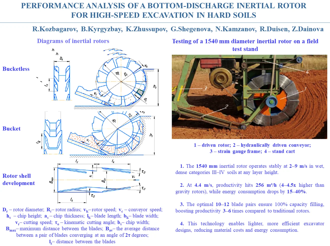
Highlights
- The 1540 mm inertial rotor achieved a productivity of 256 m³/h at a cutting speed of 4.4 m/s, which is 4-4.5 times higher than conventional gravity rotors.
- The inertial rotor reduced specific energy consumption by 15-40% through oblique cutting, inertial discharge, and elimination of soil lifting.
- The optimal design uses 10-12 blade pairs, providing up to 100% transport capacity filling, stable operation, and efficient excavation of dense soils.
1. Introduction
The economic development of the Republic of Kazakhstan depends largely on improving the efficiency of the construction and mining sectors, which can be achieved through the development and implementation of modern excavation machinery and technologies.
Earthwork accounts for a significant share of construction. Annually, more than 15-20 billion cubic meters of earthwork are performed worldwide, of which over 800 million cubic meters are carried out in Kazakhstan. The continued development of industrial facilities, hydroelectric power plants, roads, and the exploitation of mineral deposits is linked to an increase in the volume of this work, which can only be carried out using modern fleets of earthmoving and transport machinery [1].
The key machines in such complexes are rotary swing-boom excavators, used in overburden removal and open-pit mining operations. Their use increases labor productivity by 5-6 times and reduces the cost of production by 3-4 times compared to underground mining methods. At the same time, capital expenditures for quarry construction are 1.5-2.5 times lower, and development times are 3-4 times shorter.
Continuous-operation equipment with rotary excavators is widely used both in Kazakhstan and abroad. It facilitates the implementation of efficient technological processes and increases labor productivity [2].
Currently, rotary excavators are used for mining coal and other minerals, as well as for extracting kaolin, clay, sand, and gravel; they are also employed in transportation infrastructure construction and in loading and unloading operations [3].
As their applications expand, the tasks of increasing productivity, reliability, and improving the design of these machines are becoming particularly important.
The novelty of this study lies in the development of a high-speed “top-down” digging method using a bucketless inertial rotor. Unlike traditional gravity-type rotors, the proposed design utilizes centrifugal forces for material discharge. The objective is to prove that inertial discharge enables a multi-fold increase in productivity without increasing machine weight [4].
The scientific novelty of this research lies in the transition from gravity-based to inertial discharge, which removes the speed limitations inherent in current rotary systems. A key innovative aspect is the upward direction of the cutting force reaction during the “top-down” method; this naturally relieves the excavator's structural load and reduces its overturning moment. This approach allows for a multi-fold increase in cutting speeds (up to 9 m/s) without increasing the machine’s weight, reducing energy intensity through the effect of soil collapse.
2. Materials and methods
The importance of rational design in rotary excavators is demonstrated by numerous experimental and theoretical studies conducted by leading manufacturers and research institutions both in our country and abroad [5].
The modern development of excavation and transportation operations is impossible without the use of boom-type rotary excavators on crawler tracks. The limits of their application compared to other types of excavators are largely defined, yet rotary machines retain an advantage, especially when working with hard and frozen soils [6].
Fig. 1Diagrams of inertial rotors: Dr – rotor diameter; Rr – rotor radius; νk – rotor speed; νc – conveyor speed; hs – chip height; as – chip thickness; lk – blade length; bk – blade width; νr – cutting speed; τoτ0– kinematic cutting angle; bs – chip width; Bmax – maximum distance between the blades; Bav – the average distance between a pair of blades converging at an angle of 2τ degreesτ; lZ – distance between the blades
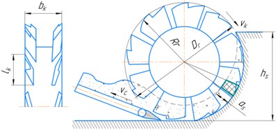
a) Bucketless
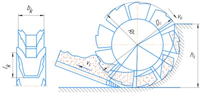
b) Bucket
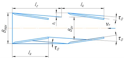
c) Rotor shell development
Today, the potential for increasing the productivity of traditional rotary excavators has been virtually exhausted. The gravity rotors currently in use limit increases in rotational speed and digging forces due to the characteristics of bucket unloading and the cutting process.
In this regard, new rotor designs are being developed to increase operating speed and efficiency without increasing the size or weight of the machines. Rotors with inertial bucket unloading, which allow material to be unloaded from top to bottom, show great promise [7].
However, such designs result in soil spillage at the face. To address this issue, a new design for the working equipment has been proposed that eliminates these shortcomings.
The key difference lies in the fact that the face is developed not by buckets, but by pairs of cutting blades moving from top to bottom, followed by the transport of the excavated material onto a conveyor. This process involves oblique cutting, with the material collapsing under the action of its own weight and centrifugal forces. This reduces energy consumption by eliminating the need to lift the soil and allows for an increase in the rotor’s rotational speed.
As a result, higher productivity is achieved with a smaller excavator size and weight compared to traditional designs.
The bottom-discharge inertial rotor consists of a shell with two rows of blades mounted at an angle to its generatrix (Fig. 1(a, c)). In the bucket version, the rear parts of the paired blades are connected by a partition (Fig. 1(b)). A distinctive feature of the design is the absence of a cutting hood. Experiments have shown that the presence of a cutting lip leads to the jamming of solid particles between it and the receiving hopper, which reduces the design’s performance. The bucket version also proved ineffective, as it limits the rotor’s transport capacity to the volume of the buckets.
When developing a face from top to bottom using an inertial rotor, the following advantages are evident: the inertial and tangential forces help feed the soil onto the conveyor at a high initial velocity, which allows for an increase in the rotor’s rotational speed; the upward cutting force reaction reduces the overturning moment, lowering the excavator’s mass and improving its stability; the energy intensity of the digging process is reduced due to oblique cutting with chipping and partial soil collapse; the collapsing soil is intensively crushed and mixed, which prevents it from getting stuck between the blades.
To ensure the reproducibility and reliability of the results, a comprehensive measurement approach was applied during the experiments:
– Instrumentation: Three strain-gauge frames integrated into the test stand structure were used to record force parameters.
– Data Acquisition: Power, torque, and rotor speed were measured using sensors with an accuracy of within 2-3 %.
– Soil Characteristics: Tests were conducted in a controlled environment using sandy soils with a bulk density of 1.95 t/m3 and a moisture content of 23.8 %, corresponding to categories III-IV soils.
– Parameter Adjustment: The methodology allowed for varying the number of blade pairs (from 10 to 12), the distance between them, and their installation angle, ensuring a complete factorial analysis.
3. Results and discussions
Preliminary tests of the inertial rotor have confirmed the feasibility of the top-down cutting process with oblique cutting and soil collapse by the blades. The optimal blade arrangement on the drum, the optimal operating and energy parameters, as well as the shape and size of the chips, have been determined. Based on these studies, a machine with an inertial rotor 1540 mm in diameter was designed, manufactured, and tested; it operates at digging speeds of 2-9 m/s in soils of categories III-IV with a moisture content of 23.8-25.6 %.
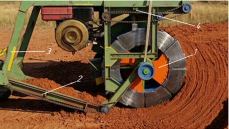
The 1540 mm-diameter rotary unit (Fig. 2), which was tested under field conditions, consists of the following main components: 1 driven rotor, 2 hydraulically driven conveyors, and a frame that is mounted on the test stand’s carriage via 3 load-sensing frames.
The rotor drive consists of an AO-83-4 electric motor, a V-belt drive with interchangeable pulleys, and a gearbox. The hydraulic drive of the conveyor includes an AO-52-4 electric motor, an NShA-46 hydraulic pump, an MPA-64 hydraulic motor, and a gearbox. A pneumatic torque-limiting clutch is installed inside the rotor.
During the experiments, power, torque, rotor speed, and feed rate were measured, as well as chip parameters. The studies were conducted in sandy soils with a bulk density of 1.95 t/m3 and a moisture content of 23.8 %. Inclusions up to 150-200 mm in size did not interfere with the unit’s operation. The design allowed for adjusting the number of blade pairs, the distance between them, and their installation angle.
To analyze the rotor parameters, the nominal geometric capacity of a pair of blades and its filling coefficient were introduced. Unlike gravity rotors, soil feed is driven by the soil’s own weight and centrifugal forces, which enables operation at high speeds and the use of cutting elements of considerable height.
These tests were supplemented by the results of field studies: the reliable performance of the inertial rotors was confirmed, and at 4.4 m/s, the throughput was 256 m3/h, which was 4.5 times higher than that of a rotor with gravity-fed buckets;the specific energy consumption of the inertial rotors during excavation at speeds of 2.1-4.4 m/s was found to be 15-40 % lower than that of the ER-25 industrial excavator, which was operating simultaneously on the same soil; cutting and transporting both sandy and clayey soils proceeds satisfactorily with the adopted blade arrangement, which has a convergence angle of 30°.
The theoretical performance of an inertial rotor in a dense medium can be determined as follows [1]:
where – rotor end feed rate; – chip height; – chip thickness.
Since , and , where – the height of the blade, we get:
where – cutting speed; – kinematic cutting angle; and – the relative heights of the chips and the cutters, respectively.
Fig. 2Testing of a 1540 mm diameter inertial rotor on a field test stand: 1 – driven rotor; 2 – hydraulically driven conveyor; 3 – strain gauge frame; 4 – stand cart
For cohesive soils, the relative height of the excavated layer can be set to 1.4, and the optimal kinematic cutting angle to , as determined by field tests of an inertial rotor with a diameter of 1540 mm, which is equal to 7°.
With these values of and , Eq. (2) takes the form:
Analysis of this formula shows that the capacity of an inertial cutting head depends on the rotor diameter, digging speed, and the height of the cutting elements, and varies over a wide range, significantly exceeding the capacity of a gravity rotor of the same diameter.
The relative height of the gravity rotor buckets is 4, and its capacity is calculated using the formula:
where – performance coefficient, which depends on soil properties, 12-29.
When processing unconsolidated soils, the theoretical capacity of an inertial rotor is higher than that of a gravitational rotor with the same parameters; for example, at 2000 mm and 2 m/s, it is 1.5 times higher at 4.0 and 3 times higher at 2.
Increasing the digging speed to 4 m/s increases the productivity of the inertial rotor by a factor of 3.0 and 6.2, respectively, compared to that of the gravitational rotor, and by a factor of 4.7 and 9.4 at m/s.
The high performance of the inertial rotor is achieved through high digging speeds and excellent transport capacity, which depends on the number of pairs and the height of the blades.
The increase in productivity achieved by increasing the height of the blades can be determined using the rotor’s transport capacity coefficient, which is defined as the ratio (in percent) of the volume of soil transported per revolution of the working body to the volume of the rotor,, calculated based on the maximum width of the buckets or the distance between the blades .
Experimental studies have shown that with 10-12 pairs of blades, the rotor achieves complete transport of the cut material. In this case, 100 % filling of the geometric capacity of the blades is observed, with 1.0-1.1. Therefore, when determining the distance between a pair of blades, one can assume that the geometric capacity of the blades corresponds to the volume of the chips being cut
where – chip width; – loafing factor; – the average distance between a pair of blades converging at an angle of 2 degrees; – blade length.
Comparing the right-hand sides of Eq. (5) and (6), assuming , , , , where – the ratio of the distance between two adjacent points on the blades to the length of the blade; – distance between the blades; – number of blades.
After performing the transformations, we obtain:
For = 1.4; 1.0, 7°, 10-12 and 1.3-1.4 [2], the maximum distance between the blades:
Using Eq. (3) and (8), it is possible to calculate the values of the inertial, gravitational, and centrifugal forces acting on the rotors, which determine their transport capacity.
The calculated values of coefficient obtained for the inertial rotor turned out to be significantly higher than those of the excavators in use, but the experimental values were lower than the calculated ones. The latter can be explained by the fact that the distance between the blades was set greater than the calculated value and only 90 % of the rotor’s transport capacity was utilized [1].
An analysis of Eqs. (7) and (8) shows that the distance between the blades – and consequently the weight of the inertial working body – corresponds to the width and weight of the rotor of the same diameter used in excavators, and remains virtually constant as the working body’s transport capacity increases due to the increased thickness of the chips being removed.
It is well known that the weight of rotary excavators depends on the nature of the soil being excavated, the boom dimensions, and the rotor diameter.
A rough comparison of the weights of excavators with inertial and gravitational rotors can be obtained based on geometric similarity [7], assuming that the machines operate under different conditions and have booms of the same length.
Given that the weights of geometrically similar bodies are proportional to the cube of the ratio of their linear dimensions (diameters), and using the values of the rotor diameters from Eq. (3) and (4), we obtain the following for rotors of the same capacity:
where , – the weights of excavators with inertial and gravity rotors, respectively.
An analysis of Eq. (9) shows that the weight of an excavator with an inertial rotor is significantly less than that of an excavator with a gravity-driven working body of the same capacity. This reduction in weight is due to the fact that an inertial rotor with a smaller diameter can operate at higher digging speeds and has a high transport capacity. Furthermore, when mining a face “from top to bottom,” the reaction force from the digging action is directed upward, which relieves the excavator’s metal structure of loads during operation and, in turn, further contributes to reducing the excavator’s weight.
The results of the experimental studies conducted on a full-scale rotor model with a diameter of 1540 mm fully support the main theoretical premises. Specifically:
– The established productivity of 256 m3/h at a speed of 4.4 m/s proves the efficiency of inertial discharge, which is 4.5 times higher than that of gravity rotors.
– The recorded reduction in energy consumption by 15-40 % confirms the hypothesis of lower energy intensity achieved by eliminating the need to lift the soil and employing oblique cutting.
– Field test data in category III-IV soils confirm the operational reliability of the bucketless design and the optimality of the selected number of blade pairs (10-12).
4. Conclusions
Summarizing the results of the studies conducted, the following conclusions can be drawn.
1) Experimental tests of the 1540 mm diameter inertial rotor confirmed its stable performance at digging speeds of 2-9 m/s in soils of categories III-IV with a moisture content of 23.8-25.6 %. It has been established that the proposed working body ensures effective excavation of dense and cohesive soils, as well as reliable transport of the excavated material regardless of the height of the excavated layer.
2) The results obtained demonstrate the high efficiency of the new design. At a digging speed of 4.4 m/s, the productivity of the inertial rotor reaches 256 m3/h, which is 4-4.5 times higher than that of gravity rotors of similar diameter. At the same time, the specific energy consumption of the process is reduced by 15-40 %, confirming the energy efficiency of the proposed solution.
3) It has been established that the optimal number of blade pairs is 10-12, at which point up to 100 % of the geometric capacity is filled and the maximum transport capacity of the working body is ensured. Increasing the digging speed to 4 m/s allows for a 3-6 – fold increase in productivity compared to traditional rotors.
4) The implementation of the inertial rotor represents a fundamental shift in excavator design, enabling the creation of lighter and more sustainable equipment. This technology provides a significant boost in productivity, lower energy consumption, and reduced material costs, confirming its high potential for industrial application.
References
-
R. A. Kozbagarov, K. A. Zhussupov, Y. B. Kaliyev, M. N. Yessengaliyev, and A. V. Kochetkov, “Determination of energy consumption of high-speed rock digging,” News of the National Academy of Sciences of the Republic of Kazakhstan, Series of Geology and Technical Sciences, Vol. 6, No. 450, pp. 85–92, 2021, https://doi.org/10.32014/2021.2518-170x.123
-
M. Gomilanovic, U. Bugaric, M. Bankovic, N. Stanic, and S. Stepanovic, “Determining the availability of continuous systems in open pits using ANFIS and a simulation model,” Energies, Vol. 17, No. 5, p. 1138, 2024, https://doi.org/10.3390/en17051138
-
Y. L. Lieberman, O. A. Lukashuk, and A. S. Shabaeva, “Modernization of rotary excavator for trenching for main pipelines,” Repair Reconditioning Modernization, No. 12, pp. 3–9, Jan. 2022, https://doi.org/10.31044/1684-2561-2022-0-12-3-9
-
P. Hartlieb and S. Bock, “Theoretical investigations on the influence of artificially altered rock mass properties on mechanical excavation,” Rock Mechanics and Rock Engineering, Vol. 51, No. 3, pp. 801–809, Nov. 2017, https://doi.org/10.1007/s00603-017-1355-3
-
S. Savkovic, P. Jovancic, S. Djenadic, M. Tanasijevic, and F. Miletic, “Development of the hybrid MCDM model for evaluating and selecting bucket wheel excavators for the modernization process,” Expert Systems with Applications, Vol. 201, p. 117199, Sep. 2022, https://doi.org/10.1016/j.eswa.2022.117199
-
Y. I. Berezhnoi, “Stability of rotary mining excavators used in the extraction of refractory raw materials from deep strata,” Refractories, Vol. 20, No. 11-12, pp. 697–699, 1979, https://doi.org/10.1007/bf01400275
-
R. Kozbagarov, K. Zhussupov, Y. Kaliyev, M. Yessengaliyev, and N. Kamzanov, “Energy intensity study for soil transportation by inertial rotor,” Vibroengineering Procedia, Vol. 48, pp. 93–99, Feb. 2023, https://doi.org/10.21595/vp.2023.23086
About this article

The authors have not disclosed any funding.
The datasets generated during and/or analyzed during the current study are available from the corresponding author on reasonable request.
The authors declare that they have no conflict of interest.

