Abstract
In recent years, research has been underway to create working bodies of excavation machines that allow digging soil at higher speeds. One of these new types of machines are excavation and transport machines with an inertial bottom discharge rotor. The paper presents the results of studies of high-speed digging and proposes a method for determining the average values of the energy intensity of soil transportation, and the proposed equations can be recommended for calculating the inertial rotor. The table of costs of specific energy consumption and productivity from the speed of rotation of the rotor at constant chip sizes is given. The analysis of studies showed that the energy intensity increases with an increase in the speed of rotation of the rotor, and the productivity grows according to a linear law. The inertial-type rotor during the test proved to be quite efficient, and the performance of the tested rotor is four times higher than that of the existing gravity-type rotor.
Highlights
- Schemes of inertial rotors
- Scheme of mining and transportation of soil by an inertial rotor
- The moment of the forces of weight and friction can be respectively expressed by the formulas
- Costs of specific energy consumption of soil transportation and productivity of the inertial rotor depending on the rotor speed at constant chip sizes
1. Introduction
At present, there is a significant development of scientific research and design developments in the field of earth-moving equipment in the Republic of Kazakhstan. At the heart of this rise are extensive and in-depth studies of Kazakh scientists. The scientific results of their research gave a strong impetus to the creation of new promising areas in the development of excavation technology [1].
Today, the hour has come for the transition to a new level of development of science and technology, on which there are every reason: firstly, the high level of economic development that the Republic of Kazakhstan has achieved at the moment; secondly, we must not forget that there are a number of machine-building plants and repair enterprises in the republic, which with full confidence can be counted on by the state in the formation of technical policy and management of the process of creating new equipment, analyzing and using patent information, introducing rationalization proposals, developments and inventions into production.
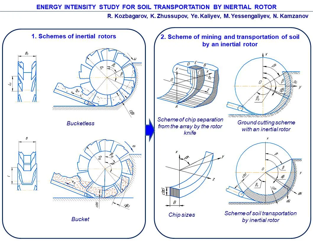
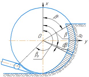
Increasing the productivity of excavation and transport vehicles with increasing volumes of earthworks is one of the most important tasks for today. This problem can be solved by using new effective methods of excavating soil with continuous machines, in particular, excavators with an inertial bottom unloading rotor (Fig. 1(a)).
Due to the novelty of the design of these machines, many issues have not yet been studied enough, including the issues of the influence of speed on the main indicators of the digging process. The research results show that with increasing speed, the specific energy intensity of the digging process also increases. However, the nature of this dependence, established by various researchers, is not the same. In addition, most of the studies were carried out with simple cutting elements and therefore their results cannot be extended to the working bodies of machines. During high-speed digging, there are also additional influencing factors that make it even more difficult to study the process of digging the soil.
One of the promising high-speed working bodies is an inertial rotor, in which there are no buckets, they are replaced by cutting elements in the form of knives ( – width; – length), and the bottom unloading of the soil occurs, excluding its lifting to the top position, as happens in existing gravity and other rotors (Fig. 1(a)). This design and the process of unloading the soil can significantly increase productivity and reduce the energy consumption of soil transportation by increasing the height of the knives.
When developing a bottom hole from top to bottom with an inertial lower unloading rotor, the following advantages of this method can be noted in comparison with the traditional design of gravity, direct-flow and centrifugal rotors [2]:
1) inertial and tangential (tangential) forces act together and contribute to the supply of soil to the conveyor at a significant initial speed, so the rotation of the rotor can be carried out at a relatively high speed;
2) the upward reaction from the cutting forces reduces the tipping moment, whereby the weight of the machines is reduced and its stability is more easily ensured;
3) the energy intensity of the cutting process, due to the design of the cutting perimeters, is significantly reduced, oblique cutting occurs with chipping of the soil and its partial collapse;
4) knives are cleaned automatically by the cut soil itself;
5) the soil, collapsing, is well crushed and moves at high speed, which prevents it from getting stuck in the space between the knives.
2. Methods
In order to determine the energy intensity of soil transportation, the performance of the inertial lower unloading rotor in various soils and to establish rational modes of its operation, the authors carried out experimental work in the field. Studies were carried out in sandy and clay soils of categories II-III. Soil density was measured with a DorNII striker at three levels along the height of the developed layer. On average, it was 12-16 strokes in the upper and 16-26 strokes in the lower layers. The cutting elements were attached to the rotor so that it was possible to change the number of pairs of knives (5, 8 and 10), the distance between them (275, 310 and 345 mm) and the angle of their installation relative to the edge of the rotor drum (6-16 degrees).
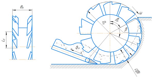
The process of soil development with an inertial rotor is based on the principle of separating the soil from the massif with knives by chipping and collapsing the soil under its own weight. The collapsed soil along the tray is carried out by pairs of knives and unloaded onto the conveyor under the action of inertia forces and the weight of the soil (Fig. 1(b)). Thus, the total energy consumption of digging is the sum of the energy consumption of cutting and the energy consumption of transporting the soil along the cut profile with its subsequent unloading onto the conveyor [3].
In this article, the authors investigate one of the important parameters characterizing the efficiency of the working element for soil development - the energy intensity of its transportation depending on the speed of rotation of the rotor at constant chip sizes.
In the existing literature, energy consumption for the elements of complex digging is usually considered jointly. But the energy costs for transporting soil, in contrast to the process of its destruction, depend on the type of soil to a small extent.
Observations of the working process of the inertial rotor in the field show that the transportation and unloading of soil occurs in a continuous stream. The cut soil with ten pairs of knives on the rotor completely falls on the conveyor. However, due to the crescent of the chip section and the cyclically changing number of knives that come into contact with the ground, the total amount of chips removed by the rotor changes continuously and cyclically.
The period of these cycles is determined by the angle of rotation of the rotor (around its axis) by an angle corresponding to the arc of the bucket trajectory between the cutting edges of adjacent knives [4].
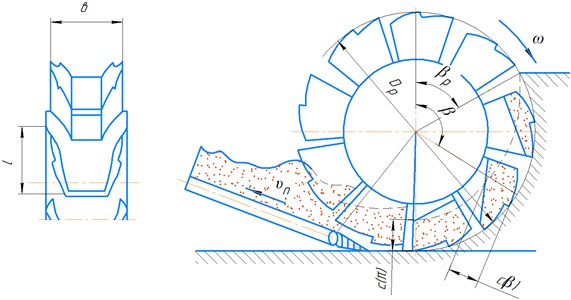
Based on these positions, the geometric shape of the total volume of chips removed by the rotor can be represented by the diagram (Fig. 2(a)) ABCDE, in which scheme cutting is carried out with four knives. Considering that the thickness of the chips varies in the radial direction according to the cosine law, the volume of chips compressed by one bucket (knife), when turning from angle to , can be expressed by the formula:
Fig. 1Schemes of inertial rotors
a) Bucketless
b) Bucket
Then the total volume of soil moving along the cutting surface will be:
where and – respectively height and width of chips; – rotor radius; – number of cutting knives; – angle corresponding to arc of ladle trajectory between cutting edges of adjacent knives.
The total volume of chips removed is measured cyclically and during the cycle time, corresponding to the time of rotation of the rotor by an angle, it grows linearly. This volume for the experimental rotor of diameter = 1,54 m and 10 pairs of knives at 200 mm, 31 mm, varies from 0,125 to 0,195 m3 and averages 0,16 m3.
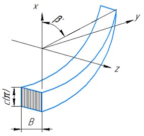
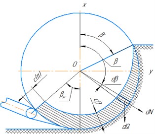
Fig. 2Scheme of mining and transportation of soil by an inertial rotor
a)
b)
c)
d)
To determine the energy intensity of soil transportation by an inertial rotor, it can be assumed that the number of knives is unlimitedly large, so the width of the removed chips tends to zero [5]. In addition, we assume that the soil between the knives is distributed evenly across the width, and along the buckets – with a variable thickness according to some regularity . To determine this pattern, consider an elementary bucket ( – width; – length) whose position in the bottom hole is determined by the angle , then the elementary volume of chips cut by the bucket is (Fig. 2(b)):
On the other hand, the elementary volume of soil in the bucket can be written as:
where – rotor feed rate; – bucket width (distance between paired knives); – rotor radius.
Comparing Eqs. (3) and (4), you can get an expression for (Fig. 2(с, d)):
where – angular velocity of the rotor.
The average value of the torque developed by the rotor when transporting the soil along the cutting plane can be determined by applying the kinetic moment change theorem: , ( – the kinetic moment of soil movement; – the main moment of all external and volumetric forces applied to soil particles).
Value is composed of moment of forces of particles weight, moment of friction forces of cut soil against cutting plane, moment of reactions acting on bucket walls equal to value of torque .
Thus, the torque on the rotor shaft:
To determine – it can be considered that the velocity vector , since the absolute velocity of the particles taken at the moment of the cut is zero, then when calculating the increment we take into account the kinetic moment at the exit from the face [5].
The second flow rate can be expressed by the equation:
And the flow rate per time will be equal , therefore, taking into account Eq. (7), you can write:
where – volumetric weight of soil, – acceleration of gravity.
The moment of the forces of weight and friction can be respectively expressed by the formulas:
3. Results
Simplifying these equations and substituting their values into Eq. (6), it can be obtained that the energy intensity of soil transportation is 28 % for the experimental inertial rotor, which is consistent with the experimental data. Therefore, the proposed equations can be recommended for calculating the inertial rotor.
The results of studies of the energy intensity of soil transportation by an inertial rotor are summarized in Table 1.
Analysis of the results of Table 1 shows that the energy intensity of soil transportation increases with increasing rotor speed, while the performance of the inertial rotor grows linearly. The inertial type rotor, the main advantage of which is the development of an earthen mass when it rotates “from top to bottom” with the collapse of the cut soil, during the test proved to be quite efficient.
Research, development and testing of excavation-transport machines with an inertial lower discharge rotor showed their high performance, low energy consumption and low dynamics of loads on soils of various hardness. It can also be noted that the lowest energy intensity of digging is achieved when excavating the soil with a knife cutting element compared to an arch-type cutting perimeter and a bucket without a bottom.
The analysis carried out by the authors also allows us to recommend the proposed excavation and transport equipment with an inertial rotor as a machine that performs a significant amount of work on excavation and soil movement, as the most promising and cost-effective for introduction into production and use in road construction.
Table 1Costs of specific energy consumption of soil transportation and productivity of the inertial rotor depending on the rotor speed at constant chip sizes (H= 1150 mm, ao= 200 mm, b= 31 mm)
Rotor speed , 1/sec | 1 | 2 | 3 | 4 | 5 | 6 | 7 | 8 | 9 | 10 |
Specific energy consumption for soil transportation, , kW·h/m3 | 0,010 | 0,012 | 0,016 | 0,022 | 0,030 | 0,042 | 0,056 | 0,072 | 0,090 | 0,110 |
Inertial rotor capacity , m3/h | 40 | 80 | 120 | 160 | 200 | 240 | 280 | 320 | 360 | 400 |
4. Conclusions
By summarizing the results of experimental studies, the following conclusions can be drawn:
1) proposed procedure for determination of average energy consumption for the process of soil transportation by inertial rotor.
2) the operability of the inertial rotor, which effectively develops and unloads soil on the receiving conveyor, as well as the stable transportation of soil by the receiving conveyor at inclination angles up to 36 and belt speed m/s, is established 2-5 m/s;
3) the largest productivity of the rotor reached in the studied ranges of chip parameters and digging speeds 1,54 was 254 m3/h, which is 4 times higher than that of the gravitational rotor of the same diameter;
4) optimal in terms of energy intensity, chip parameters at a given knife height were: chip thickness 180-200 mm, width 30-40 mm, the ratio of chip thickness to width 3-5, with a larger chip thickness, energy intensity increases due to the deterioration of the chip separation process and an increase in the height of the scallops removed by the second row of knives;
5) complete transportation of cut soil is observed with the number of pairs of knives 10 and some crumbling at 5 and 8.
In general, the high performance of the inertial rotor, its sufficient strength when encountered with obstacles, the low energy intensity of the digging process and good work on wet and sticky soils make it possible to conclude that on the basis of inertial rotors continuous earth-moving machines of various purposes of high productivity of relatively low weight and, in particular, boom rotary excavators operating on soils of different hardness can be created.
References
-
D. P. Volkov, Machines for Earthworks. 2012, p. 447.
-
S. Blouin, A. Hemami, and M. Lipsett, “Review of resistive force models for earthmoving processes,” Journal of Aerospace Engineering, Vol. 14, No. 3, pp. 102–111, Jul. 2001, https://doi.org/10.1061/(asce)0893-1321(2001)14:3(102)
-
P. Hartlieb and S. Bock, “Theoretical investigations on the influence of artificially altered rock mass properties on mechanical excavation,” Rock Mechanics and Rock Engineering, Vol. 51, No. 3, pp. 801–809, Mar. 2018, https://doi.org/10.1007/s00603-017-1355-3
-
Kozbagarov R. A., Zhusupov K. A., Kaliev E. B., Yessengaliyev M. N., Kochetkov A. V., and Kamzanov N. C., “Development of control suspension of attachment of a bulldozer,” NEWS of National Academy of Sciences of the Republic of Kazakhstan, Vol. 4, No. 442, pp. 166–174, Aug. 2020, https://doi.org/10.32014/2020.2518-170x.97
-
R. A. Kozbagarov, K. K. Shalbayev, M. S. Zhiyenkozhayev, N. S. Kamzanov, and G. T. Naimanova, “Design of cutting elements of reusable motor graders in mining,” Series of Geology and Technical Sciences, Vol. 3, No. 453, pp. 128–141, Jun. 2022, https://doi.org/10.32014/2022.2518-170x.185
About this article

We express our gratitude to the leadership of the Academy of Logistics and Transport for their assistance in carrying out scientific work.
The datasets generated during and/or analyzed during the current study are available from the corresponding author on reasonable request.
The authors declare that they have no conflict of interest.
