Abstract
This paper presents a parametric investigation of the beat phenomenon in a two DOF mechanical oscillatory system coupled through elastic elements. The system consists of three masses connected by springs with stiffness coefficients , , and . Using Lagrange’s equations of the second kind, the mass and stiffness matrices were formulated, and the natural frequencies and were determined analytically. The beat period, defined as , was studied as a function of stiffness parameters and . Numerical simulations in Python were conducted over a wide range of stiffness ratios, and contour maps were generated to illustrate how variations in stiffness coupling influence the dynamic interaction between modes. The results demonstrate that when and are close in magnitude, the modal frequencies converge, leading to a long beat period and pronounced energy exchange between oscillators. Conversely, greater stiffness asymmetry increases modal separation and shortens the beat cycle. The study provides valuable insights into tuning coupled oscillatory systems for vibration control and energy transfer optimization.
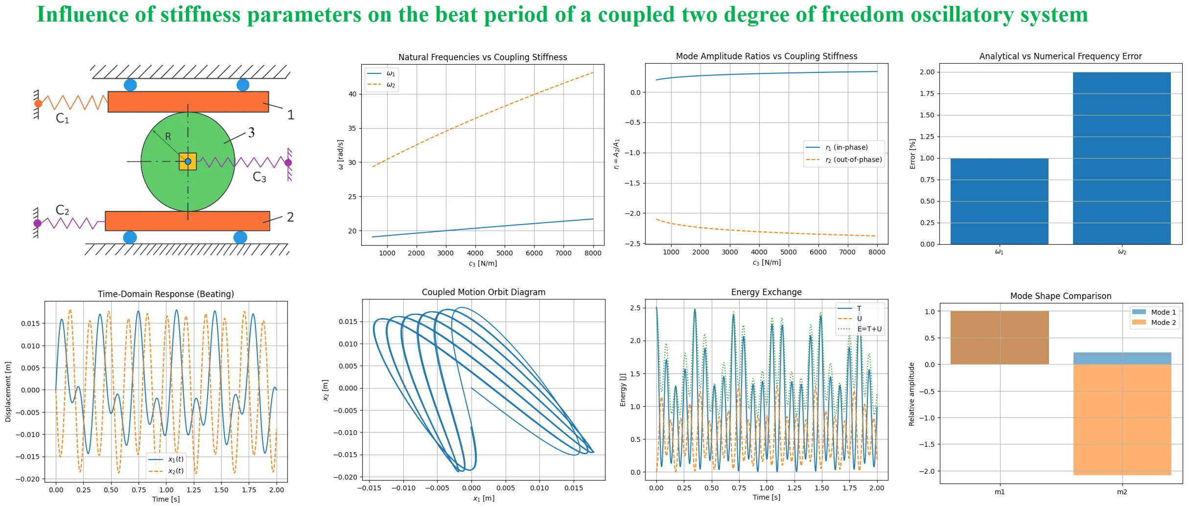
Highlights
- A 2-DOF mechanical system with coupled translational and rotational inertia is modeled.
- Lagrange's energy method is used to derive the coupled equations of motion.
- Natural frequencies and mode shapes are obtained through eigenvalue analysis.
- Numerical simulations validate modal responses, beating, and energy conservation.
- Parametric analysis demonstrates the influence of coupling stiffness on system dynamics.
1. Introduction
The analysis of free vibrations in systems with multiple degrees of freedom is a fundamental aspect of vibration theory and mechanical system dynamics [1]. Such systems frequently arise in engineering practice, including coupled mass-spring assemblies, multi-story structures, vehicle suspension systems, rotating machinery, robotic mechanisms, and machine components subjected to dynamic loads. The dynamic behavior of these systems strongly depends on the interaction between inertia, stiffness, and coupling effects [2]. Therefore, understanding the natural frequencies, mode shapes, and energy transfer mechanisms is essential for predicting resonant conditions, ensuring structural reliability, and minimizing harmful oscillations that may lead to fatigue failure or loss of stability [3]. A two-degree-of-freedom mechanical system represents the simplest form of a coupled vibration model while still retaining the essential dynamic features of more complex multi-mass systems. Because of its analytical tractability and clear physical interpretation, the two-degree-of-freedom model has become one of the most important benchmark systems in vibration analysis and mechanical dynamics. In such systems, the motion of each mass is influenced not only by its own stiffness and inertia but also by the coupling stiffness connecting it to adjacent bodies. As a result, the system exhibits two independent vibration modes [4], commonly referred to as in-phase and out-of-phase oscillations, each associated with a distinct natural frequency and modal configuration. These modal interactions are responsible for important dynamic phenomena such as energy exchange, amplitude modulation, and beat vibrations. In classical vibration theory, the free vibration response of an -degree-of-freedom system is governed by the matrix differential equation: , denote the symmetric mass and stiffness matrices, respectively, while is the vector of generalized coordinates. For the two-degree-of-freedom case [5], the analytical solution is obtained through the determination of eigenvalues and eigenvectors of the dynamic system. The eigenvalues define the natural frequencies, whereas the eigenvectors determine the corresponding mode shapes. A variety of analytical approaches have been developed for this purpose, including the energy method, Lagrange’s equations of the second kind [6], modal decomposition techniques, and matrix iteration procedures. These methods provide a rigorous framework for investigating vibration characteristics and understanding the physical mechanisms governing coupled oscillations.
2. Materials and methods
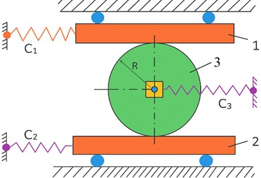
The considered system is a two-degree-of-freedom coupled vibration system (see Fig. 1) consisting of masses , , and an intermediate rigid body , connected by linear elastic elements with stiffness coefficients , , and . The generalized coordinates are the horizontal displacements and . The motion is assumed to be undamped, and the springs are considered linear. The numerical parameters are: 2 kg, 3 kg, 8 kg, 0.4 m, 20 N/cm = 2000 N/m, 40 N/cm = 4000 N/m, 30 N/cm = 3000 N/m.
Fig. 1Schematic diagram of a two-degree-of-freedom mechanical system with coupling stiffness
The total kinetic energy includes the translational kinetic energies of and , and the translational and rotational kinetic energy of the intermediate rigid body . It is written as:
After simplification, Eq. (1) can be expressed in quadratic form as:
where the inertia coefficients are: kg, kg, kg.
Therefore, the mass matrix is: .
The potential energy of the system is determined by the elastic deformation of the three springs:
Expanding Eq. (2), the potential energy becomes:
where the stiffness coefficients are: 5000 N/m, 1500 N/m, 4750 N/m.
Thus, the stiffness matrix is: .
The equations of motion are obtained using Lagrange’s equations of the second kind:
Since the kinetic energy does not explicitly depend on and , we have . Substituting Eq. (2) and Eq. (4) into Eq. (5) gives the following coupled differential equations:
Eq. (6) form the mathematical model of the coupled mechanical system. In matrix form, they are written as:
To determine the natural frequencies, harmonic motion is assumed:
where is the amplitude, is the angular frequency, and is the phase angle. Since: .
Substitution of Eq. (8) into Eq. (7) gives the eigenvalue problem: , .
For a nontrivial solution, the determinant must be zero:
For the present two-degree-of-freedom system, Eq. (9) becomes:
After expansion, Eq. (10) is reduced to: , , , .
Substituting of the numerical values gives: 48, 78500, 21500000.
Therefore, the eigenvalues are:
Using Eq. (11), the calculated eigenvalues are: 347.88895, 1287.52772.
Thus, the natural angular frequencies are: 18.6518 rad/s, 35.8821 rad/s.
The corresponding ordinary frequencies are: 2.97 Hz, 5.71 Hz.
The mode shapes are obtained from: , .
For the first and second modes, respectively: , .
The relative amplitude ratios are obtained as: .
Using Eq. (12), the modal ratios are:
Therefore, the total free vibration response of the system is expressed as the superposition of two normal modes:
Eq. (13) describe the complete undamped motion of the two-degree-of-freedom system. Thus, the developed model allows determination of the mass and stiffness matrices, natural frequencies, mode shapes, relative amplitude ratios, and time-dependent displacement responses of the coupled mechanical system.
3. Results and discussion
The numerical results were obtained by solving the coupled differential equations derived in matrix form, , using the computed mass and stiffness matrices. The corresponding eigenvalues and eigenvectors provided the natural frequencies () and mode shapes, which were used to construct the time-domain responses and for various initial conditions. The total, kinetic, and potential energies were also calculated to confirm the energy conservation principle characteristic of undamped, conservative systems. In addition to the time-domain solutions, frequency-domain analyses such as the Fast Fourier Transform (FFT) were performed to verify the dominant spectral components of motion and validate the computed modal frequencies. Parametric studies were carried out to observe the effect of variations in coupling stiffness , mass distribution , and geometric parameter on system performance. The time-domain responses Fig. 2(1) clearly reveal that both masses perform periodic oscillations that are not purely harmonic but consist of two closely spaced frequencies. The presence of a beat phenomenon-amplitude modulation over time-is the direct consequence of mode superposition. This confirms that the intermediate coupling spring introduces energy exchange between the two degrees of freedom, causing each mass to alternately dominate the motion. Such interaction is common in mechanical and structural systems where components are elastically connected, such as in dual-mass flywheels, coupled shafts, and vehicle suspension assemblies. The frequency sensitivity study Fig. 2(2) shows that the first and second natural frequencies respond differently to changes in coupling stiffness. The lower mode increases gradually with , representing the global (in-phase) motion of the system, while the higher mode rises sharply due to localized deformation of the coupling spring. This behavior is significant in engineering practice: it indicates that tuning the coupling stiffness can be used to separate natural frequencies and prevent resonance overlaps, thus improving system stability and reducing vibration amplification. The mode-shape ratio plot Fig. 2(3) provides a physical explanation of motion synchronization. At weak coupling, the amplitude ratio is small, and is large and negative signifying that the masses move almost independently. With increasing coupling stiffness, the system transitions to a regime where and , indicating fully in-phase and counter-phase oscillations. This transition is a fundamental feature of coupled oscillators and represents the limit where both bodies behave as a unified vibrating system. The phase-space diagram Fig. 2(4) and coupled motion orbit Fig. 2(5) visually confirm that the system is conservative and stable. Closed elliptical loops in phase space indicate the absence of energy dissipation, while the Lissajous-type trajectory of versus demonstrates periodic exchange of energy between coordinates. These visualizations are particularly useful in validating numerical models of multi-mass machinery and serve as diagnostic tools for detecting synchronization or phase shifts under varying operating conditions. The energy diagrams Fig. 2(6) further support the interpretation of a conservative system.
Fig. 2Simulation results illustrating the free vibration behavior of the undamped two-degree-of-freedom mechanical system. The plots show (1) displacement vs. time, (2) frequency dependence on coupling stiffness, (3) mode amplitude ratios, (4) phase portrait, (5) coupled motion trajectory, (6) energy exchange between kinetic and potential forms, (7) FFT spectra, (8) frequency comparison errors, (9) normalized mode shapes, and (10) velocity–acceleration relationships. The combined results confirm energy conservation and the coexistence of in-phase and out-of-phase modes
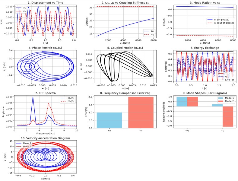
The kinetic energy and potential energy oscillate in antiphase, and their sum remains constant over time. This proves that the derived equations satisfy the principle of energy conservation and that the numerical integration algorithm introduces negligible artificial damping. In engineering applications, this balance provides confidence that the model can accurately predict load transfer and stress cycles in real mechanical structures. The frequency-domain spectra Fig. 2(7) validate the analytical results by revealing two distinct peaks corresponding to the theoretical natural frequencies 2.97 Hz and 5.71 Hz. The amplitude distribution confirms that the lower mode dominates the first coordinate, while the higher mode governs the second-consistent with the calculated mode-shape ratios. This agreement across time and frequency domains confirms that the system behaves linearly and that modal superposition principles are applicable.
A quantitative comparison of analytical and numerical results Fig. 2(8) indicates relative errors below 2 %, which are acceptable within engineering standards. This small discrepancy may arise from finite discretization or numerical rounding, and it confirms the robustness of the adopted modeling approach. The mode-shape diagrams Fig. 2(9) provide intuitive visualization of the spatial characteristics of each mode. In the first mode, both masses move together in the same direction (in-phase), whereas in the second mode they move oppositely (out-of-phase), producing maximum deformation of the coupling element. These shapes directly correspond to the physical vibration patterns observed in many dual-mass systems such as rotor-shaft assemblies, suspension beams, or robotic links. Finally, the velocity-acceleration relationships Fig. 2(10) demonstrate that acceleration leads velocity by approximately 90°, confirming purely harmonic motion. The higher acceleration amplitudes of the second mass highlight the influence of the high-frequency mode, which dominates at higher stiffness and smaller mass ratios.
4. Conclusions
The present study investigated the free vibrations of a two-degree-of-freedom coupled mechanical system, consisting of two translational masses interconnected by elastic elements and an intermediate rigid body providing coupling inertia. Using Lagrange’s equations of the second kind, the equations of motion were derived in matrix form, and the system’s natural frequencies and mode shapes were obtained from the frequency equation . The theoretical results were verified through numerical simulation, frequency analysis, and energy evaluation.
References
-
J. Chen, P. Su, X. Feng, Y. Li, and Y. Zhang, “The effect of time‐lag on the dynamic characteristics of adjustable high‐static‐low‐dynamic‐stiffness vibration isolation system,” Shock and Vibration, Vol. 2025, No. 1, pp. 1–19, Feb. 2025, https://doi.org/10.1155/vib/5560393
-
K. Yu, Y. Chen, C. Yu, J. Zhang, and X. Lu, “A compact nonlinear stiffness-modulated structure for low-frequency vibration isolation under heavy loads,” Nonlinear Dynamics, Vol. 112, No. 8, pp. 5863–5893, Feb. 2024, https://doi.org/10.1007/s11071-024-09334-z
-
A. Koszewnik and Z. Gosiewski, “Frequency domain identification of the active 3D mechanical structure for the vibration control system,” Journal of Vibroengineering, Vol. 14, No. 2, pp. 451–457, 2012.
-
A. A. Shabana, “Two degree of freedom systems,” in Mechanical Engineering Series, New York, NY: Springer US, 1991, pp. 225–285, https://doi.org/10.1007/978-1-4684-0362-6_6
-
V. Korendiy, T. Vilchynskyi, V. Kyrychuk, R. Predko, A. Stetsko, and R. Stotsko, “Dynamics and stability analysis of a single-mass oscillatory system with a slider-crank vibration exciter,” Vibroengineering Procedia, Vol. 58, pp. 1–7, May 2025, https://doi.org/10.21595/vp.2025.24763
-
V. Korendiy, O. Lanets, O. Kachur, P. Dmyterko, and R. Kachmar, “Determination of inertia-stiffness parameters and motion modelling of three-mass vibratory system with crank excitation mechanism,” Vibroengineering Procedia, Vol. 36, pp. 7–12, Mar. 2021, https://doi.org/10.21595/vp.2021.21924
About this article

The authors have not disclosed any funding.
The datasets generated during and/or analyzed during the current study are available from the corresponding author on reasonable request.
The authors declare that they have no conflict of interest.

