Abstract
The article develops and validates the feasibility of calculating the soft shell thickness used to eliminate evaporation losses from welded oil storage tanks during operation. Based on the assessment of existing technical means for reducing losses from evaporation of oil and petroleum products, a conclusion is made about the need to develop a new technical means – an inner soft shell, which is an oil-and-petrol-resistant soft shell located inside the tank. The design of vertical and horizontal cylindrical tanks with soft shell is proposed. The principle of the tank operation was checked on a mock-up. An experimental setup was built, tests were carried out. According to the test results, evaporation losses are excluded when using soft shell in tanks. The maximum shell thickness is calculated under conditions that prevent unacceptable deformations during operation. The minimum thickness is determined based on the tensile strength conditions of the soft shell’s self-weight during installation.
1. Introduction
Global crude oil production exceeds 74.853 million barrels per day in 2025.[1] A significant fraction is lost at various stages: according to industry estimates, total losses in the petroleum sector reach about 9.5 % (4.0 % at production, 3.5 % at refining, and 2.0 % during transport and storage). Among these, evaporation from storage tanks is one of the major contributors. It is estimated that 50 to 90 million tons of hydrocarbons are emitted annually into the atmosphere from oil and petroleum product handling operations. Evaporation losses alone account for up to 75 % of all storage losses and represent a major source of methane (up to 86 %) and greenhouse gas emissions (up to 42 %) in the upstream and downstream sectors.
To mitigate evaporation losses, various technical measures are employed. Floating roofs and pontoons are the most widely used and effective means, reducing losses by 70-98 %. However, their high capital cost makes them economically unviable for small- and medium-sized tanks, as well as for mobile storage vessels. Therefore, a more cost-effective and versatile solution is needed.
A promising alternative is the use of a flexible, oil-resistant inner shell that floats on the product surface and isolates it from the atmosphere. This concept has been successfully tested on model barrels. However, before scaling up to full-size tanks, the material and wall thickness must be rationally selected.
This work presents a comprehensive approach to determining the thickness of such a soft shell. The maximum thickness is constrained by the need to avoid excessive compressive stresses and local buckling during operation, while the minimum thickness is dictated by tensile strength during installation (lifting under self-weight). The methodology is illustrated with a calculation example for several polymeric materials suitable for contact with hydrocarbons.
2. Design and operating principle
The soft, gas-tight shell made of oil- and petrol-resistant polymer installed inside the tank, floating freely on the liquid surface (Fig. 1). A breather pipe with a valve connects the shell interior to the atmosphere. During filling, the shell collapses, displacing air outward; during emptying, it expands, drawing air inward. Thus, the vapor space above the product is eliminated, and the breathing losses (both “standing losses” and “working losses”) are completely prevented. A safety valve on the tank is set to a higher pressure than the breather valve to ensure that the shell always operates first. A condensate drain pipe at the bottom allows removal of any moisture that may condense inside the shell [2].
Fig. 1Tanks with soft shells: 1 – tank shell; 2 – tank bottom; 3 – tank roof; 4 – soft shells; 5 – pressure/vent valves; 6 – pipe; 7 – safety relief valve; 8 – condensate drain pipe; 9 – level gauge; 10 – cages
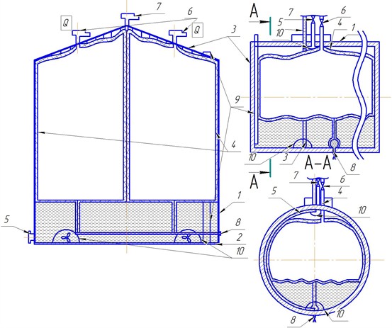
The shell is manufactured with openings for the level gauge and sampling tube, enabling standard operations without rotation of the shell. The upper part is suspended from the tank roof via lugs and suspension pipes, while the lower part is secured to the condensate drain pipe. A stationary gas analyzer in the upper part monitors tightness.
3. Experimental verification
To validate the concept, a experimental setup was built comprising two 209-litre model tanks (vertical and horizontal), each equipped with soft shells (Figs. 2,3). The test liquid was automotive gasoline. Multiple transfer cycles were simulated: 135 litres (101.5 kg) were pumped from one tank to the other per cycle, and 20 cycles (total 2 tonnes) were performed. The total mass of the entire setup was weighed before and after the series of transfers. Eight measurements were taken before and eight after (Table 1) [3].
Statistical processing gave:
1) Standard deviation of the mean before: 0.044 kg, after: 0.040 kg.
2) Confidence limits (0.95, = 2.365): 0.104 kg, 0.094 kg.
3) Non-excluded systematic error 0.1 kg (scale error). Since / 0.8, the random error is negligible.
4) Final results: 212.51±0.1 kg; 212.50±0.1 kg. The difference is within the measurement uncertainty.
The relative error was 0.02 %, and repeatability (2.77·) was 0.26 %, indicating high precision.
Fig. 2Experimental model: 1 – tank shell; 2 – soft shells; 3 – pressure/vent valves; 4 – safety relief valve; 5 – pump; 6 – ball valve; 7 – scales; 8 – frame
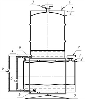
Fig. 3Experimental barrels
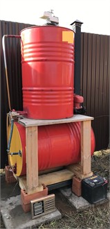
Table 1Measurement results of the experimental setup mass
No. | Time and date | Mass, kg | Mean, kg | Deviation, kg |
Before transfers | ||||
1 | 18.09.2021 10:12 | 212.5 | 212.51 | –0.0125 |
2 | 18.09.2021 10:15 | 212.6 | +0.0875 | |
3 | 18.09.2021 10:18 | 212.3 | –0.2125 | |
4 | 18.09.2021 10:21 | 212.6 | +0.0875 | |
5 | 18.09.2021 10:24 | 212.4 | –0.1125 | |
6 | 18.09.2021 10:27 | 212.5 | –0.0125 | |
7 | 18.09.2021 10:30 | 212.7 | +0.1875 | |
8 | 18.09.2021 10:33 | 212.5 | –0.0125 | |
After transfers | ||||
9 | 18.09.2021 22:08 | 212.5 | 212.50 | +0.0125 |
10 | 18.09.2021 22:11 | 212.4 | –0.0875 | |
11 | 18.09.2021 22:13 | 212.5 | +0.0125 | |
12 | 18.09.2021 22:16 | 212.4 | –0.0875 | |
13 | 18.09.2021 22:18 | 212.6 | +0.1125 | |
14 | 18.09.2021 22:21 | 212.3 | –0.1875 | |
15 | 18.09.2021 22:24 | 212.6 | +0.1125 | |
16 | 18.09.2021 22:28 | 212.6 | +0.1125 | |
For comparison, the standard natural loss rates for tanks without a pontoon are 0.41 kg per tonne of product received (spring-summer, 2nd climatic zone), and with a pontoon – 0.36 kg/t. For the transferred 2 tonnes, these would amount to 0.82 kg and 0.72 kg, respectively. In the experiment, no loss was detected. Thus, the soft inner shell completely eliminates evaporation losses during filling and emptying.
Additionally, a method for estimating condensate accumulation inside the shell was developed. For typical conditions (incoming air volume 50 m3, 60 % RH, temperature drop from 29 °C to 5 °C), the condensed water per cycle is about 0.525 kg; for 30 cycles ~15.75 kg (0.03 % of the operation volume). This is negligible for operation but provides an extra benefit – reduction of bottom water in the product.
4. Theoretical justification of thickness calculation
During operation, the shell repeatedly crumples and unfolds. Excessive folding leads to local bending and fatigue damage. To avoid this, the shell must have lower flexural stiffness. At the same time, during installation it is lifted by its upper part, so the material must withstand tensile stress from its own weight.
Flexibility and buckling. For a cylindrical shell, Euler’s formula for a rod gives the flexibility:
where is the minimum radius of gyration. For a 10 m high, 7.5 m radius cylinder, varying thickness from 1 to 35 mm changes only from 1.3333 to 1.3318 – i.e., negligible. For common oil-resistant polymers (nitrile rubber, fluororubber SKF-26, fluoroplastic F-246, thermopolyurethane), the critical flexibility:
is much higher (Table 2), meaning that the shell loses stability in the plastic range, and Euler’s formula is not applicable. The Yasinski’s empirical formula requires material-specific coefficients which are unavailable for these polymers.
Table 2Mechanical properties of polymers [4]
Material | Elastic modulus, MPa | Tensile strength, MPa | , MPa | Critical flexibility | soft shell flexibility ( = 1) 10 m, 7,5 m | ||
Nitrile rubber | 4 | 7 | 9.8 | 12 | 3.8 | 4.9 | = 1.3333 (1 mm) =1.3318 (35 mm) |
Fluororubber | 4 | 7 | 17.6 | 20.6 | 18.0 | 8.8 | |
Fluoroplastic | 80 | 490 | 30 | 47 | 26.1 | 15 | |
Thermopolyurethane | 28 | 414 | 12 | 70 | 2.8 | 6 | |
Buckling of thin cylindrical shells. For thin shells with large deflections, von Kármán’s equations reduce to the Lorenz-Timoshenko formula for axial compression:
At Poisson’s ratio 0.3, this gives:
however, real shells suffer from geometric imperfections and thickness variations, so a reduction factor is introduced (Table 3). For / > 1500 (which holds for the minimum technological thickness of 1 mm and typical tank radii), 0.09. Hence the realistic critical stress is:
To avoid plastic deformation, the compressive stress must not exceed the yield strength (for polymers, taken as half the tensile strength: / 2. This gives an upper bound on thickness:
Table 3Reduction factor k for shell buckling [5]
250 | 500 | 750 | 1000 | 1500 | |
0.18 | 0.14 | 0.12 | 0.10 | 0.09 |
Tensile strength during installation. When the shell is lifted, the wall experiences tensile stress from self-weight. The minimum wall thickness is found from:
where is the total shell mass, – gravitational acceleration. This is the lower bound.
Combining Eqs. (5) and (6):
For the lifting lugs, the minimum thickness (based on tear strength) is:
where is the lug length.
5. Example calculation for a 2000 m3 tank
A tank of 2000 m3 volume has radius 7.5 m. A 3D model (Kompass 3D) gave the shell mass 871.2 kg (density 950 kg/m3). Using the properties from Table 2 and applying condition Eq. (7), we obtain the allowable thickness ranges (Table 4) [6].
Table 4Allowable thickness range for the 2000 m3 tank shell
Material | (self-weight), mm | , mm | Technological minimum, mm |
Nitrile rubber | 0.037 | 473 | 1.0 |
Fluoroplastic F-246 | 0.010 | 21 | 1.0 |
Thermopolyurethane | 0.030 | 10 | 1.0 |
Fluororubber SKF-26 | 0.020 | 84 | 1.0 |
The computed minimum thickness is two orders of magnitude smaller than the practically feasible 1 mm. Therefore, the lower bound is not restrictive; the thickness is set by manufacturing standards. The maximum allowable thickness is far above 1 mm, so buckling is not a concern for these materials. Consequently, a 1 mm thick shell is sufficient for all considered polymers.
For the lifting lugs, the minimum required thicknesses (from tear strength) are given in Table 5. These are also below 3 mm and technologically acceptable.
Table 5Minimum lug thickness
Material | , mm |
Nitrile rubber | 2.91 |
Fluoroplastic F-246 | 0.95 |
Thermopolyurethane | 2.37 |
Fluororubber SKF-26 | 1.62 |
The lugs are not subjected to compressive loads during service, so no buckling check is needed for them.
6. Results
1) The experimental study confirms that soft inner shell completely eliminates evaporation losses during filling/emptying operations.
2) A theoretical model for thickness selection is developed, combining buckling strength (upper bound) and tensile strength during installation (lower bound).
3) For the tested polymers and typical tank dimensions, the minimum required thickness (from self-weight) is far below the technological minimum of 1 mm, so thickness is determined by manufacturability.
4) The maximum thickness limit from buckling is not critical for 1 mm shells because the calculated critical stress exceeds the yield strength by a large margin.
5) The additional benefit of condensate collection is quantified.
7. Conclusions
1) A soft inner shell has been proposed and experimentally validated for eliminating evaporation losses from oil storage tanks.
2) The proposed design is applicable to both vertical and horizontal tanks and does not require major structural modifications.
3) A robust methodology for determining the shell thickness has been established, ensuring both operational stability and installation safety.
4) For the materials and tank sizes studied, a thickness of 1 mm is sufficient; no thicker shell is needed from strength or stability considerations.
5) The use of soft inner shells offers a cost-effective alternative to pontoons, especially for small and medium tanks, and also reduces water content in the stored product through condensate collection.
References
-
“OPEC online annual statistical bulletin 2026.” OPEC, https://publications.opec.org/asb/filedownload/154/asb/332 (accessed 2026).
-
R. R. Gabdinurov and M. M. Gareev, “Tank for storing oil and oil products,” (in Russian), Russian Patent 202016, 2021.
-
R. R. Gabdinurov and M. M. Gareev, “The application of soft shells inside the tank to prevent losses of oil and oil products from evaporation,” (in Russian), Transport and Storage of Oil Products and Hydrocarbons, No. 4, pp. 39–44, 2021, https://doi.org/10.24412/0131-4270-2021-4-39-44
-
I. A. Barvinskiy and I. E. Bravinskaya, Handbook of Molded Thermoplastic Materials. (in Russian), 2001.
-
K. F. Chernykh, Nonlinear Theory of Elasticity in Mechanical Engineering Calculations. (in Russian), Leningrad: Mashinostroyeniye Publ., 1986, p. 336.
-
R. R. Gabdinurov and M. M. Gareev, “Soft shell materials thickness calculation to reduce evaporation losses in oil tanks,” Transport and Storage of Oil Products and Hydrocarbons, No. 5-6, pp. 53–57, 2024.
About this article

The authors have not disclosed any funding.
The authors express their gratitude to Ufa State Petroleum Technological University for the opportunity to conduct research and to all colleagues who provided assistance in the experimental work.
The datasets generated during and/or analyzed during the current study are available from the corresponding author on reasonable request.
Ruslan R. Gabdinurov: conceptualization, investigation, methodology, writing-original draft preparation, visualization. Mursalim M. Gareev: supervision, validation, writing-review and editing, project administration.
The authors declare that they have no conflict of interest.

