Abstract
A novel complementarity-based screening framework is developed for vibration- and shock-induced disengagement of a spring-loaded self-locking pawl latch used for remote handling of a portable railway wheel chock. The engagement geometry is treated explicitly. The critical opening angle is derived from the engagement depth and the engagement radius, and a retention factor carries the wear, tolerance and elastic-approach allowances. Contact forces and moments are formulated for the locked and the incipient-opening configurations, and the equivalent-wedge self-locking condition is recovered only as their plane-flank limit. Because the catch element is a cylindrical pin, the retention condition within the planar rigid-contact model is tan ≤ , in which is the same angle that fixes the critical opening angle; the wedge form understates the required friction coefficient by a factor of approximately 2.4 for the stated worked-example dimensionless proportions ( = 5° and /= 0.208). The latch is then treated as a unilateral-contact system governed by five dimensionless groups: the frequency ratio, the damping ratio, the severity number , the pulse duration , and a preload number = /() introduced here. Three cases are separated. For the seated latch the criterion is loss of contact, < . The preload-free oscillator is retained as an explicitly labelled upper-bound idealisation. The seated latch with a lift-off threshold is formulated as a linear complementarity problem. Numerical integration of that model over 0.1 ≤ ≤ 40 supports the conservative algebraic screening bound < 0.6(). The damping ratio moves this boundary by less than 4 %, and the worst frequency ratio is sub-resonant, so the critical damping ratio of the preload-free model does not describe the preloaded latch. Reproducible Euler-Bernoulli and Rayleigh calculations for an explicitly defined reduced shaft model place the first bending frequency between 3.2 and 62.0 Hz, which identifies the grip-to-pivot amplification, rather than the damping ratio, as the measurement of highest value. For the nominal set of the worked example the model predicts a lift-off acceleration of 1389 m/s2; at the worst corner of the parameter domain it predicts 167 m/s2, and a conditional guard-banded screening calculation at = 1 excludes that corner under the assumed input uncertainties. All quantities are model predictions conditional on assumed parameters; no experimental validation is claimed.
1. Introduction
Rolling stock is secured against spontaneous movement on station, siding, marshalling and dead-end tracks by a portable wheel chock placed against the wheel. The chock is positioned by hand or with a setting fork. In 1520 mm gauge practice the device is commonly called a brake shoe, and that term is used here. In North American regulatory usage the same term usually denotes the friction element acting on the wheel tread, so the device considered here corresponds to a portable wheel chock in that terminology. Traceable patent literature documents rail-mounted safety chocks, automatic anti-theft locking arrangements, remotely released track blocks and portable wheel chocks [1-4]. These mechanisms secure a vehicle or retain the chock on the rail, but they do not provide the self-locking fork-to-chock coupling analysed in this study.
The closest known device combines a brake shoe with a catch fitting and a setting tool. The tool is a lever with a handle at one end and a pin-type receiving element at the other. The pin is introduced into a mating hole in the catch fitting, so the shoe can be positioned behind the wheel and later lifted off while the shunter remains to the side, outside the hazardous zone behind the wagon [4]. The pin-hole joint, however, does not form a mechanical self-locking grip and is held only by the alignment of the pin with the hole. Removal is performed by lifting the shoe rather than by tractive extraction under guaranteed retention, and the joint provides neither automatic latching on forward insertion nor controlled release by rotation. Reliable retention of the shoe while it is pulled off the rail under load is therefore not assured, and precise positioning of the pin relative to the hole is required.
A recently developed kit addresses these limitations. The brake shoe carries a catch assembly on its non-working upper part, with a transverse catch element and an undercut. The working head of the setting fork carries a mating self-locking mechanism with a spring-loaded pawl and a cam surface. The catch element and the pawl form a complementary self-locking joint. The tractive force transmitted through the fork shaft increases the engagement instead of releasing it, so the shoe can be extracted from the rail without the shunter’s hand approaching it. Disengagement requires a deliberate rotation of the fork shaft about its longitudinal axis. That rotation drives the catch element against the cam surface of the pawl and withdraws it from engagement. Because the catch assembly sits above the working sole, the braking properties of the sole are unaffected. The kit reduces the biomechanical load on the hands, shoulder girdle and lumbar region of the shunter and shortens the time spent in the hazardous zone. This is in line with the stated aim of the underlying invention and with computational estimates of the mechanical power expended by train assemblers during manual coupling-related operations [5]. In a broader sense the kit follows the engineering-controls approach to occupational risk reduction, in which the hazard is removed at its source rather than managed by administrative measures alone. Such source-level elimination of exposure is consistent with the international trend, reflected in “Vision Zero”-type safety programmes, towards removing personnel from the hazardous zones of shunting operations.
The static self-locking property of the pawl–catch joint, that is, retention which increases under tractive load and cannot be released by that load alone, has been established analytically from the geometry of the engagement and the friction properties of the mating steel surfaces. Reliable operation of a hand-held railway tool also depends on its behaviour under vibration and shock. Hand-transmitted and vehicle-induced vibration is a recognised occupational hazard for railway workers [6]. The measurement and evaluation of such exposure is standardised by ISO 5349-1 and ISO 5349-2 [7, 8], and limit and action values for hand-transmitted vibration are prescribed in the European Union by Directive 2002/44/EC [9]. The question is therefore whether transverse vibration or shock transmitted through the fork shaft during coupling, transport and extraction could cause a transient loss of contact or a parasitic rotation of the pawl, even though the joint is stable under a purely static axial load. This paper answers that question by treating the latch as a unilateral-contact system with a preload threshold. The engagement geometry is formulated explicitly, the contact conditions are separated into three cases, and the seated case with a lift-off threshold is written as a linear complementarity problem. The harmonic problem is reduced to a criterion in the plane of the frequency ratio and an excitation severity number , and the shock problem is treated as the response to a half-sine acceleration pulse of dimensionless duration = . The main contribution is the preload number that governs the transition between the seated and the free behaviour, together with the conservative algebraic screening bound and the guard-banded decision rule that follow from it. The brake-shoe kit is the engineering case study to which the framework is applied.
The contribution of this paper is not the oscillator model of a pawl, which is standard. Nor is it the half-sine shock response, which is classical, or the wedge form of the self-locking condition, which dates from the study of self-locking mechanisms. What is new is the treatment of the latch as a unilateral-contact system with a preload threshold, and the consequences that follow from it. A preload number is introduced that governs the transition between the seated and the free behaviour. The severity number and the preload number are shown to combine into a single decision variable whose uncertainty is smaller than that of either, because the spring rate and the engagement angle cancel in their ratio. The complementarity formulation unifies two results that are usually reported separately, a lift-off margin and a dynamic magnification, and shows that they are the two limits of one model. It also reverses two conclusions that the preload-free treatment suggests: damping has only a weak influence on the Case C boundary within the examined preloaded range, and the governing frequency ratio is sub-resonant. Finally, the screening criterion is stated as a guard-banded decision rule rather than as a comparison of point estimates. Acceptance of a design then depends on the uncertainty of the four quantities that can be measured for a specific installation and excitation scenario. The resulting contribution is a mathematical model for an engineering retention mechanism: it combines unilateral contact, dimensionless reduction, numerical integration and measurement-decision uncertainty in one auditable screening procedure.
2. Design of the self-locking coupling
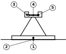
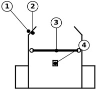
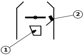
The catch assembly of the brake shoe is designed as a reinforced bracket with two lateral cheeks, guiding chamfers and a transverse catch element placed above the working surface of the sole (Fig. 1, Fig. 2). The working head of the fork is U-shaped and contains two guiding cheeks, a support hook and a spring-loaded pawl (Fig. 3(a)); the guiding chamfers and cheeks reduce the need for precise alignment when the head is introduced into the catch assembly. On forward motion of the head the transverse catch element is received in the throat formed by the support hook and the guiding cheeks and automatically engaged by the spring-loaded pawl (Fig. 3(b)), after which the tractive force required to extract the shoe from the rail can be transmitted through the fork shaft without manual contact with the shoe.
Fig. 1General view of the kit. 1 – brake shoe, fitted with the catch assembly; 2 – fork, with working head and T-handle
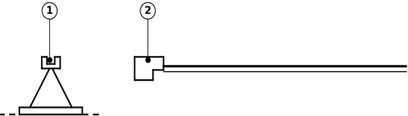
Fig. 2Catch assembly of the brake shoe: a) arrangement on the non-working upper part (1 – support body of the shoe; 2 – sole (working friction surface); 3 – catch assembly; 4 – transverse catch element; 5 – mounting (seating) surface of the catch assembly, for a removable-module version); b) enlarged view (1 – lateral cheeks of the catch assembly; 2 – guiding chamfers; 3 – transverse catch element; 4 – lock undercut)
a)
b)
The retaining surface of the pawl bears on the transverse catch element so as to form an undercut. The undercut is characterised by the angle , defined in Section 3.1 for the actual geometry of the device. The inclination is chosen so that the line of action of the resultant contact force, under tractive load, passes on the engagement side of the pawl pivot. The reaction then produces a moment that presses the pawl against the catch element, so an increase in the tractive force increases the engagement rather than opening the pawl. This is the self-locking principle that governs single-degree-of-freedom self-locking mechanisms with rigid links in general [10-12]. As a local contact approximation, the interface may be treated as an equivalent undercut wedge, for which the static self-locking condition is:
where is the coefficient of friction between the pawl and the catch element. For a typical steel-on-steel pair, = 0.15-0.20, the self-locking angle arctan is about 8.5-11°, which corresponds to the lower part of the claimed undercut range of 5-15°. Adverse operating conditions such as lubrication, oil products, frictional dust, moisture or icing all reduce . The design value of within the claimed range is therefore chosen close to its lower bound, preferably 5-8°, so that the margin given by inequality Eq. (1) survives a reduced effective friction coefficient.
Fig. 3Working head of the fork: a) design (1 – shaft; 2 – working head; 3 – guiding cheeks; 4 – support hook; 5 – spring-loaded pawl; 6 – cam surface of the pawl; 7 – pawl spring; 8 – pivot axis of the pawl; 9 – retaining surface of the pawl); b) locked position on the transverse catch element of the shoe (1 – spring-loaded pawl, engaged with the undercut; 2 – position indicator, signalling full engagement)
a)
b)
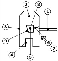
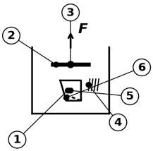
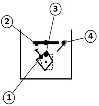
Fig. 4Latch unit: a) locked position (1 – spring-loaded pawl; 2 – cam surface; 3 – retaining surface, engaged with the undercut of the catch element; 4 – pawl spring; 5 – pivot axis; 6 – lock undercut, providing self-tightening of the grip under tractive force F); b) deliberately released (rotated) position (1 – spring-loaded pawl, rotated about the pivot axis against the spring, the initial locked position shown by the dashed line; 2 – cam surface, now in contact with the catch element; 3 – retaining surface, withdrawn from the undercut; 4 – position indicator, showing the unlocked state)
a)
b)
A single nominal steel-on-steel value cannot represent all service conditions: experimental studies of static friction show significant sensitivity to surface roughness, traces of lubricant and wear debris [13]. Criterion Eq. (1) is accordingly evaluated over a friction-coefficient interval rather than at a single nominal value. Release of the joint requires two deliberate actions. The residual tractive preload is first relieved by a small forward motion of the shaft. The shaft and the working head are then rotated about the longitudinal axis through 30-90°. That rotation displaces the contact zone from the retaining surface onto the cam surface of the pawl, converts the imposed rotation into a retraction against the spring, and withdraws the retaining surface from the undercut. A free-body confirmation that the contact reaction produces a closing moment under tractive load is given in Section 3 (Fig. 7).
Eq. (1) is written here in its equivalent-wedge form. It is not an independent assumption: Section 3.2 derives the general contact condition for the locked configuration and shows that Eq. (1) is its planar, stationary-contact limit, and Table 1 states the circumstances in which the wedge form ceases to be conservative.
3. Dynamic model of the pawl under vibration and shock excitation
The overall structure of the model developed in this section is summarised in Fig. 5. Eq. (1) guarantees that the joint cannot be opened by a purely axial tractive force; Fig. 4(a) and Fig. 4(b) illustrate the locked and the forcibly unlocked states of the pawl. During shunting the fork–shoe assembly may also be subjected to transverse vibration or shock. It is transmitted through the shunter’s hands to the shaft, through contact of the fork or the coupled shoe with the rail and rolling stock, or through the coupling manoeuvre itself. Vehicle-induced acoustic and vibrational loads of this kind have been shown to reach levels relevant to occupational exposure assessment [6], which gives a plausible order of magnitude for the shock component. These disturbances act as a base excitation at the pivot of the pawl. Eq. (1) excludes opening under a static load, so the question is whether the excitation can produce a transient rotation large enough to reduce the engagement margin. Analogous safety problems arise in pawl-based automotive latch systems, where inertial forces can generate an opening moment about the pawl pivot and cause unintended release; combined theoretical and numerical analyses have been used to evaluate the inertia-load resistance of such latches [14]. Virtual-testing studies have likewise shown that latch failure may involve inertial or vibration-induced activation that conventional quasi-static retention assessment does not reveal [15].
Fig. 5Logical roadmap of the modelling approach, from the latch geometry through the mathematical and dimensionless formulation to the stability criterion, shock analysis and resulting design recommendations. Source: authors’ own work

3.1. Engagement geometry, sign convention and the critical opening angle
The pawl rotates about the pivot axis O. The right-handed frame is defined with the axis along the pivot and the axis along the direction of the tractive force transmitted through the fork shaft. The rotation is measured from the seated position and is positive in the opening direction, that is, in the direction that withdraws the retaining surface of the pawl from the undercut of the catch element. All moments about the pivot are positive in the same sense, so the spring preload moment is written with > 0.
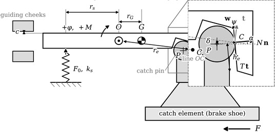
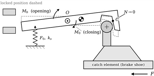
The geometry is defined in Fig. 6, drawn as a generic parameterised model rather than from the released drawing. The catch element of the kit carries a transverse cylindrical pin, and the retaining surface of the pawl bears on that pin rather than on a plane flank. Two consequences follow and are used below. The contact normal passes through the pin axis P, so its direction is fixed by the angular position of the contact point on the pin and not by a manufactured surface angle. The withdrawal direction w is the common tangent at C, perpendicular to that normal. The angle between the tangential direction of the pawl at C and the withdrawal direction is therefore the angle between the two radii OC and PC, a purely geometric quantity. Three further quantities are read from the figure. The engagement depth is the overlap between the retaining surface and the undercut, measured along the direction of withdrawal. The engagement radius runs from the pivot to the contact point C. The contact position is measured at the pin axis, from the line of action of the tractive force to the radius PC. Disengagement occurs when the rotation consumes the whole overlap. The velocity of C due to a rotation about O is perpendicular to OC and has magnitude , and only its projection on the withdrawal direction reduces the overlap. The critical opening angle therefore follows as:
Only the ratio of the two lengths enters, so with the relative engagement depth = / the critical angle is = /. No absolute dimension of the engagement is needed anywhere in the analysis, and none is assumed below.
The equality = holds only for a plane flank whose contact radius is perpendicular to the withdrawal direction. For the cylindrical pin of this device the two angles differ, as Section 3.2 shows. Eq. (2) replaces the previously assumed value of by a ratio that can be measured on the manufactured pair without disclosing any absolute dimension.
Fig. 6Engagement geometry of the pawl-catch joint, drawn as a generic parameterised model: a) locked configuration, with the engagement detail enlarged; b) incipient-opening configuration, at which the contact reaction vanishes. O – pivot; P – axis of the cylindrical catch pin; C – contact point; G – centre of mass of the pawl; re, rG, rs – lever arms; he – engagement depth measured along the withdrawal direction w; α – angular position of the contact on the pin, measured from the load line; ψ – angle between the radii OC and PC, equal to the angle between the tangential direction t at C and w; a – pin radius; δ – offset of the pin axis from the line OC; c – pawl-slot clearance; the guiding-cheek clearance is included in the tolerance allowance Δt; Nn and Tt – normal and tangential components of the contact reaction; F – tractive force on the catch element; F0, ks – spring preload and rate. The rotation φ and all moments are positive in the opening sense
a)
b)
In service the effective overlap is smaller than the nominal one. Three contributions are subtracted: the depth lost to wear of the retaining surface and of the seat, ; the worst-case tolerance stack on the overlap, ; and the elastic approach under load, , comprising the local contact deformation and the deflection of the bracket cheeks. The effective critical angle is:
where ≤ 1 is the engagement-retention factor. No absolute dimension is needed at any point below. Eq. (2) contains the two lengths only through their ratio, so the reference value = 0.10 rad used in Section 4 corresponds to an engagement ratio / = , that is, an engagement depth of about one tenth of the engagement radius. The retention factor is a ratio in the same way: an allowance for wear, tolerance stack and elastic approach amounting to 27 % of the engagement depth gives = 0.73 and = 0.073 rad. Both quantities are stated as ratios throughout, so the results transfer to any set of absolute dimensions that satisfies them, and the paper does not depend on the released drawing.
3.2. Contact forces and moments in the locked and incipient-opening configurations
Let n be the unit outward normal of the retaining surface at C and t the unit vector in the plane of possible relative sliding, directed along the withdrawal sense. The reaction transmitted to the pawl by the catch element is:
with at impending slip in the opening sense. Introducing the signed moment arms and , the contact moment about the pivot in the locked configuration is:
and the joint is self-locking, in the sense that the reaction produced by the tractive load acts to close rather than to open the pawl, when:
Inequality Eq. (6) is the general form of the self-locking condition and is stated entirely in terms of the drawing geometry and the friction coefficient. It admits a compact reduction for the present device. The contact normal of a cylindrical pin passes through its axis, so the friction direction is the common tangent at C and the vectors and are orthogonal. The moment arms then become and cos , where is the angle between OC and PC introduced in Section 3.1. Eq. (6) reduces to:
so that the single angle governs both the critical opening angle of Eq. (2) and the static retention of the joint. This condition is exact within the planar rigid-contact model, and it is not the same as Eq. (1). The wedge form tan ≤ is recovered only when = , which requires a plane flank whose normal makes the angle with the load and whose contact radius is perpendicular to the withdrawal direction. For a cylindrical pin the two angles differ by the inclination of OC, and the wedge form is non-conservative whenever > . For the stated worked-example dimensionless proportions of Fig. 6, = 5° and /= 0.208. Equation (8) then gives 12.0°, so the friction coefficient required for retention is = 0.213 rather than tan = 0.087 from Eq. (1), a ratio of approximately 2.4. Eq. (1) should therefore be read as the plane-flank dealization, and the design condition for the device is Eq. (7). Table 1 states when each may be used.
The angle can itself be expressed without any absolute dimension, which is what makes the condition usable at the design stage. The contact point lies on the pin, so the perpendicular distance from the pin axis to the line OC equals a sin , and therefore:
where is the pin radius and is the offset of the pin axis from the line joining the pivot to the contact point. Their ratio, rather than either absolute dimension, controls . The assumed worked-example value = 0.208 is used only for the dimensionless comparison above and is not presented as a measured device dimension. Combining Eq. (8) with Eq. (7), the joint is self-locking for every admissible contact position provided that:
and it is self-locking irrespective of friction when the offset falls on the closing side of the line. Eq. (9) is a design rule that requires no dimension at all, only the ratio of an offset to the pin radius: for = 0.10, 0.15, 0.20, 0.25 and 0.30 the admissible ratio is 0.099, 0.148, 0.196, 0.243 and 0.287. The pivot must therefore be placed so that the line from it to the contact point passes within roughly pin radii of the pin axis. Retention is in this sense governed by the position of the pivot relative to the pin axis and not by any manufactured angle, which is the practical form in which the condition should be carried onto the drawing.
In the incipient-opening configuration the normal force vanishes and with it the contact moment (5). The pawl is then held on its seat by the spring preload alone, and the seating constraint is released when the opening moment produced by the base acceleration exceeds . This threshold separates the contact cases of Section 3.4; it is a contact condition and not an equation of motion.
Table 1Validity of the equivalent-wedge approximation (Eq. (1)) relative to the general condition Eq. (6)
Departure from the idealised geometry | Effect on the wedge model | Still conservative? |
Plane flank, stationary contact centroid, OC perpendicular to | None – Eq. (1) is the exact planar limit of Eq. (6) | Yes |
Cylindrical catch pin, as in the present device | The exact condition is Eq. (7), ≤ ; Eq. (1) understates the required friction by the inclination of OC | No – use Eq. (7) |
Contact position migrates on the pin under load, wear or clearance | , and through it , is a contact position and not a manufactured angle; it must be specified as an admissible range | No – evaluate Eq. (6) over the range |
Edge contact after rounding of the pawl tip by wear | Contact normal rotates; effective increases and contact pressure rises | No – the margin is consumed by wear |
Skewed, non-planar contact line | Out-of-plane reaction component produces a moment not represented in the planar model | No – resolve the reaction in three dimensions |
Cam surface or guiding cheeks contact first | Load path bypasses the retaining flank | Indeterminate – identify the actual load path |
Contaminated interface (oil, grease, dust, icing) | falls below the design lower bound | Yes if is taken at its lower service bound |
Elastic compliance of the bracket cheeks | Relative displacement reduces the effective overlap | Yes if of Eq. (3) is included |
3.3. Lumped-parameter model of the pawl
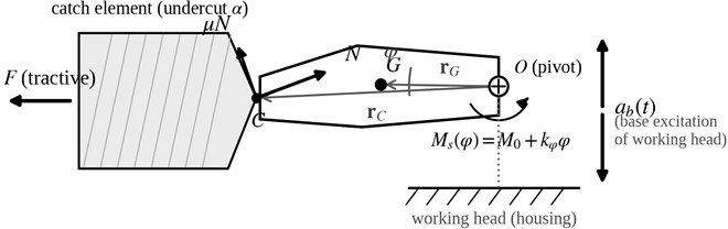
The pawl is represented as a rigid body of mass m and mass moment of inertia rotating about its pivot axis O (Fig. 7). This follows the lumped-parameter approach used for single-degree-of-freedom self-locking mechanisms [10], for dynamic modelling of self-locking components under non-stationary excitation [16], and for latch-mediated spring-actuated systems more generally [17]. Dynamic modelling of self-locking parking pawls has similarly shown that pawl reliability should be evaluated at the system-dynamics level, and that wear-sensitive contact geometry may substantially influence the engagement behaviour [18]. The pawl is restrained by its compression spring, which provides a preload moment about the pivot in the closing direction and an incremental restoring moment for rotations from the locked position. An equivalent viscous damping represents internal friction and the effect of sand, frictional dust or grease in the mechanism. By the engagement geometry, the contact moment about the pivot produced by the reaction at C, , is of closing sign under tractive load (Fig. 7), so the analysis below considers the excitation acting against the spring alone. The latch is a unilateral-contact system: while the opening component of the disturbing moment stays below the combined closing preload and contact moments, the pawl remains seated and no relative rotation occurs. The linear oscillator model that follows neglects this threshold and assumes that relative rotation can begin immediately under the disturbance torque; it is retained as an upper bound and is identified as Case B in Section 3.4. For translational base excitation transmitted to the working head, linearization about the locked equilibrium gives:
where is the torsional stiffness of the latch referred to the pivot and is the position vector of the pawl centre of mass relative to the pivot. The term is the translational acceleration of the working head, and the subscript denotes the component about the pivot axis. The peak inertial moment is therefore bounded by ≤ , where is the peak transverse acceleration. For angular excitation of the working head the disturbing moment is instead. Translational and angular excitation must not be mixed in a single scalar estimate. The translational case is analysed here because it is the one directly associated with measured hand-transmitted accelerations. The spring preload and the spring rate play distinct roles. The preload sets the threshold moment that an opening disturbance must overcome before the pawl can leave its seat, whereas the incremental stiffness governs the response after relative rotation begins. Under the small-angle approximation, and for an approximately constant effective spring lever arm , the equivalent torsional stiffness referred to the pivot is:
where and are the undamped natural circular frequency and natural frequency of the pawl about its locked position. The free-body and dynamic model is shown in Fig. 7.
To expose the governing dimensionless parameter groups explicitly, the angular displacement and time are normalised as = / and = , respectively. For harmonic base acceleration , Eq. (10) then takes the dimensionless form:
where primes denote differentiation with respect to the dimensionless time , / is the frequency ratio, ] is the damping ratio, and /() is the dimensionless excitation severity number. Thus, the harmonic response of geometrically different pawl mechanisms is governed by only three dimensionless parameters, , and .
Fig. 7Free-body and dynamic model of the spring-loaded pawl under transverse base acceleration ab(t): O – pivot axis; C – contact point at the undercut; G – centre of mass; N, μN – normal and friction components of the contact reaction; Ms(φ) – spring moment (preload M0 plus incremental restoring moment kφφ); F – tractive force on the catch element Source: authors’ own work
The previous formulation contains four dimensionless groups. A fifth is required, because the pawl is pressed onto its seat by the spring and cannot move until the opening moment overcomes the preload. Introducing the preload moment = , the preload number is:
that is, the ratio of the spring preload moment to the moment required to rotate the pawl through the whole engagement against the incremental stiffness. It is the group that distinguishes the contact cases of Section 3.4: → 0 recovers a preload-free oscillator, and → ∞ a rigidly seated pawl. Two identities follow. The ratio of the severity number to the preload number is:
that is, exactly the ratio of the peak inertial moment to the preload moment. Eq. (16) is independent of and of , so the seating decision requires only the pawl mass, the mass-centre offset, the installed preload force and the spring lever arm. Replacing by = multiplies both and by 1/, so their ratio is unaffected by wear and tolerances.
The steady-state amplitude of the pawl rotation follows from Eqs. (10-12) as:
The factor (, ) is the dynamic magnification factor for harmonic torque excitation of the rotational oscillator; the term “transmissibility” is deliberately avoided, since the classical base-motion transmissibility contains an additional (2)2 term in the numerator and refers to a different response quantity. Accidental unlatching requires the retaining surface of the pawl to leave the undercut, i.e. the rotation amplitude must reach the critical opening angle determined by the engagement depth, so the condition for stable retention under harmonic excitation is . Recalling the excitation severity number introduced in Eq. (14):
the retention condition against vibration-induced disengagement takes the compact dimensionless form:
and the angular stability factor may be defined as . For each damping ratio this defines a stability boundary in the plane, that is, a dynamic stability map of the latch. Combinations of design and excitation lying below the boundary retain the shoe, whereas the region above the boundary near resonance corresponds to potential disengagement. The criterion neglects both the preload threshold and the closing contact moment , so any positive preload and any positive tractive force shift the actual behaviour further into the stable region.
Eq. (19) holds for a pawl that possesses a relative degree of freedom at all times, that is, for a latch whose installed preload has been lost. It is retained below as Case B and is not a description of the nominal latch.
3.4. Three separated contact cases
The latch is a unilateral-contact system, and three configurations must be distinguished. They are collected in Table 2 and are not combined into a single margin.
Case A, the nominally preloaded seated latch. While the pawl is seated it has no relative degree of freedom and the problem is purely one of contact. With 0 the dimensionless reaction moment at the seat:
where is the ormalized excitation. The failure criterion is loss of contact, not rotation: the pawl leaves its seat when . Equivalently, the pivot acceleration at which the seat opens is:
No dynamic magnification enters Case A. The factor describes a system that possesses a relative degree of freedom, and a seated pawl has none, so the seating condition is evaluated instantaneously. The resonance sensitivity of Eq. (19) does not apply to the nominally preloaded latch.
Case B, the preload-free latch with positive incremental stiffness. This is the model of Eqs. (10) and (14) and corresponds to = 0. It is retained as an upper-bound screening dealization. The state arises when the installed preload is lost while the spring rate is retained. Four mechanisms produce it: a spring assembled at its free length through an omitted shim or spacer; an interrupted preload path through a failed spring seat or retainer; relaxation or settling of the spring; and wear of the seat that increases the installed length beyond the free length. Because and are both set to zero, Case B bounds every configuration with a non-negative preload, but it does not predict the behaviour of the nominal latch.
Case C, seated contact with a lift-off threshold. The complete formulation retains both the seating constraint and the dynamics after lift-off. Writing the equation of motion together with the seat reaction and imposing that the pawl cannot penetrate its seat gives the linear complementarity form:
supplemented by the -seating impact law: when the pawl returns to = 0 with 0, the post-impact velocity is with the coefficient of restitution [0, 1]. The perfectly plastic value = 0 is used as the baseline and > 0 is examined in Section 4 as the vibro-impact case. The failure criterion is max ≥ 1. Eq. (22) contains both limits: with = 0 and ≡ 0 it reduces to Case B, and while it reduces to the seating Eq. (20) of Case A.
Table 2The three contact cases
Case | Governing relation | Contact condition | Failure criterion | Status |
A – nominal, seated | 0, no relative freedom | 0 | Loss of contact: > | Nominal configuration |
B – preload-free | ≡ 0 imposed a priori | 1 | Upper-bound idealisation | |
C – seated with lift-off | ≥ 0, ≥ 0, 0 | Complete formulation |
Because the axial tractive force produces a closing rather than an opening moment on the pawl (Fig. 7), the conservative dynamic case corresponds to minimum axial load. The vibration analysis is therefore performed for 0, which represents initial coupling, transport of the coupled shoe and the moment immediately after traction is released. A finite positive tractive force is treated as an additional stabilising contribution.
The frequency range specified in ISO 5349-1 for hand-transmitted vibration assessment should not be read as the dominant excitation spectrum of the fork-shoe system. ISO 5349-1 and ISO 5349-2 provide a framework for the measurement and evaluation of occupational exposure [7, 8]. The actual spectral content transmitted to a hand-held mechanical system depends on the excitation source, the coupling conditions and the operator’s interaction. Experimental measurements on impact-type hand tools show tool-dependent tri-axial spectra and pronounced hand–arm resonant behaviour in the 16-50 Hz range [19]. The vibration transmitted from powered hand tools to the upper limb has been shown to depend on posture, grip force and excitation, with frequencies below 25 Hz also significant [20]. The dynamic stability of the pawl is therefore evaluated in terms of the dimensionless frequency ratio = / over the range 0 ≤ ≤ 3, rather than by assuming that any particular assessment band represents the dominant operational excitation.
3.5. From grip acceleration to pivot acceleration
The excitation quoted for hand-held tools is the acceleration at the grip, whereas the disturbing moment of Eq. (11) requires the acceleration at the pivot, which is located at the working head 1.75 m away. If the shaft is treated as a rigid body, the accelerations of the grip point H and of the pivot O are related by:
For hand-guided motion the centripetal term is negligible, and the angular term is already contained in the head acceleration. The elastic effect is the one that matters: the shaft is a slender tube carrying a concentrated mass at the head, so the assembly possesses its own bending and torsional modes. Writing () for the transfer of transverse acceleration from grip to pivot, the severity numbers become:
where, () is the frequency-dependent transfer factor for harmonic excitation, whereas is the peak grip-to-pivot transfer factor for a half-sine pulse of duration . Both factors are provisionally set to unity until the corresponding transfer functions are measured, and every criterion is therefore applied to the effective severity number. To determine whether shaft flexibility can be neglected, Table 3 uses an explicitly defined reduced-order shaft model rather than an arbitrary frequency range. The shaft is represented as a uniform Euler–Bernoulli steel tube of length = 1.75 m, outside diameter 32 mm, wall thickness 3 mm, density = 7850 kg/m3 and Young’s modulus = 210 GPa. These inputs give a shaft mass 3.75 kg and flexural rigidity 6.10 kN·m2. For the unloaded beam, the bending frequencies are calculated from , with 4.730 and 7.853 for the first two non-rigid free-free modes, for the pinned–pinned case and 1.875 for the clamped-free case. For a clamped shaft carrying a concentrated tip mass mₜ, the first-mode Rayleigh estimate is , evaluated for 0.5, 3.0 and 7.5 kg. The pawl frequency is calculated independently from Eq. (13) and the reference parameters of Table 5. Thus, Table 3 contains reproducible calculated outputs of the stated reduced model, not worked-example numbers. The values are used only to test whether = 1 can be assumed; measured modal properties of the manufactured assembly still require released CAD mass properties or an experimental modal test. A 20 % stiffness error changes the calculated frequencies by approximately 10 %. Integrated numerical and experimental identification provides the appropriate validation route [21-23].
Table 3Calculated bending-frequency bounds for the reduced shaft model and the pawl reference frequency
Mode | Boundary conditions / payload | Calculated frequency |
1st bending | Free-free, bare fork | 62.0 Hz |
2nd bending | Free-free, bare fork | 170.9 Hz |
1st bending | Pinned at both hands, bare fork | 27.4 Hz |
1st bending | Clamped at grip, free tip, bare fork | 9.7 Hz |
1st bending | Clamped at grip, head mass 0.5 kg | 7.9 Hz |
1st bending | Clamped at grip, head + fittings 3.0 kg | 4.7 Hz |
1st bending | Clamped at grip, coupled brake shoe 7.5 kg | 3.2 Hz |
Pawl rotation about its pivot | Reference parameter set, Eq. (13) | 66.9 Hz |
The reduced-model calculation supports two conclusions. First, the assembly cannot be assumed to provide a rigid support for the pawl. Depending on the grip boundary and coupled tip mass, the calculated first bending frequency ranges from 3.2 to 62.0 Hz and therefore brackets the 16-50 Hz comparison band; cannot be assumed close to unity throughout that band. Second, the free-free shaft value of 62.0 Hz is within 8 % of the pawl frequency of 66.9 Hz. This proximity means that modal interaction cannot be excluded, although its magnitude requires the coupling stiffness and measured mode shapes. Head-rotation, joint/contact and torsional modes are not reported in Table 3 because the required head inertia and joint stiffness are unavailable. Until is measured, conclusions remain limited to the modelled degree of freedom.
Rotation of the shaft about its longitudinal axis is the deliberate release motion and requires 30° to 90°, imposed by the operator as a rigid-body motion after the tractive preload has been relieved. A vibration-induced rotation is an elastic twist and is bounded by the strength of the tube. With a shear yield stress ≈ 205 Mpa the largest elastic twist over the length of the shaft is:
The elastic-yield estimate indicates that a release rotation of 30-90° cannot be produced by purely elastic shaft twist. It does not, however, exclude a smaller torsional component contributing to pawl opening. Until the torsional transfer function and release kinematics are measured, torsional excitation is retained as an unquantified limitation of the present model.
In addition to sustained vibration, the working head experiences transient shocks during coupling, riding of the shoe over rail irregularities and impacts of the coupled assembly against obstacles. The shock is represented by a half-sine base-acceleration pulse of peak value and duration :
and Eq. (10) with the disturbing moment of Eq. (11) is integrated numerically. The integration is performed in dimensionless time with an adaptive Runge-Kutta scheme of order 5(4), at relative and absolute tolerances of 10-8 and 10-10 and a maximum step of /200. The integration window extends six free-vibration periods beyond the end of the pulse, so that the maximum of the free response is captured. Refining the step limit and the tolerances by a further order of magnitude, or doubling the post-pulse window, changes the reported peak values of by less than 0.1 %. The peak rotation is expressed through the dimensionless amplification , which depends only on the dimensionless pulse duration and the damping ratio. The retention condition then reads , where is the shock severity number. Presenting the response over the whole axis avoids postulating particular pulse durations without experimental justification. IEC 61373 is formally intended for equipment mounted on railway vehicles rather than for hand-held shunting tools, but its separation of vibration and shock qualification provides a useful comparative framework for defining laboratory excitation scenarios for subsequent prototype testing [24].
3.6. Multi-axis bound
For a general base acceleration and an angular acceleration of the working head, the moment about the pivot axis is bounded by:
in which only the two components perpendicular to the pivot axis contribute through the mass-centre offset. The component along the pivot axis is reacted by the guiding cheeks and produces a bearing load rather than an opening moment. The in-plane resultant of two equal and in-phase components exceeds the single-axis value by at most . The angular term is smaller. For a rigid-body swing of the fork about the grip, ≈ /= 57 rad/s2 at = 100 m/s2, so 1.9×10⁻³ N·m against = 0.144 N·m, that is 1.3 % of the translational term. The two become comparable only at ≈ 4.2×10³ rad/s2. Multi-axial excitation is therefore covered by applying a factor of 1.41 to .
3.7. Spring model, parameter provenance and the acceptance rule
The relation assumes both a linear spring and a lever arm that does not change as the pawl rotates. With the spring compression and , the spring moment is and its derivative at the locked position is:
so the omitted term is proportional to the installed preload. Dividing by the retained term gives:
where is the installed compression of the spring. For the reference set = 6.7 mm and = 20 mm, so a lever arm changing by 10 % over the engagement angle adds a third to the torsional stiffness and moves the natural frequency from 66.9 to 77.2 Hz. The correction is one-sided for a lever arm that grows with the opening rotation, so the constant-arm assumption underestimates the stiffness and overestimates both and ; their ratio, Eq. (16), is unaffected. The measurement required is the force–displacement curve of the spring over its working range and the lever arm at two or three rotations.
The provenance of the parameters is stated in Section 4, where the nominal set is introduced. Only four quantities are taken from published sources; everything else is assumed. The distinction matters because the framework identifies which conclusions are structural and which remain parameter-dependent. In the examined Case C domain, damping has a weak influence after lift-off, whereas preload controls seating directly. The worst corner fails the conditional guard-banded screen under the declared input uncertainties, while the equivalent-wedge form understates the required friction coefficient for the assumed pin geometry. These statements remain conditional on the idealised contact and transfer assumptions.
Table 4 states, for each quantity, what it currently rests on, the method that would establish it, and which criterion it controls.
Table 4Provenance of the parameters and the criteria they control
Quantity | Present basis | Method that would establish it | Controls |
, , | Assumed for the worked example | Weighing; centre of mass by balance or from the released drawing | , /, |
/, , , | Assumed; only the ratio is used | Drawing dimensions and inspection of the manufactured pair | by Eq. (2); Eq. (6) |
Assumed as part of the 27 % allowance | Worst-case stack of the dimensional tolerances | , hence | |
, | Assumed as part of the 27 % allowance | Durability test; Hertzian estimate with bracket deflection | , hence |
Assumed linear rate, no spring data available | Measured force-displacement curve over the working range | , , | |
Assumed; governs the decision variable | ( – ) from measured lengths, or a load cell at assembly | , / | |
Assumed constant, see Eq. (29) | Measured over the engagement angle, Eq. (28) | , , /, | |
Scenario value | Free-decay logarithmic decrement or half-power width [25] | Case B directly; weak influence on Case C after lift-off | |
Literature interval | Tribometer on the actual pair, dry, oiled, dusty and iced [26] | Eq. (6) only | |
, | Prescribed excitation levels; not measured in the present study | Calibrated tri-axial accelerometers installed at the handle and pawl pivot | , , |
, | Assumed equal to 1; grip-to-pivot transfer not measured | Simultaneous acceleration measurements at the handle and pivot; ratio of response spectra or transfer functions | , , |
The excitation amplitudes and are prescribed model inputs rather than measured quantities. The transfer factors and are provisionally set equal to unity because the grip-to-pivot transfer function of the complete fork assembly is unavailable. Consequently, all numerical stability margins reported in this study are conditional on the specified excitation levels and on the assumption 1.
Because the groups are products of powers, relative standard uncertainties combine through the exponents, and the decision variable / carries the smallest uncertainty of the three severity measures, since and appear in and with the same exponent and cancel. The criteria are therefore applied as decision rules rather than as comparisons of point estimates: the no-lift-off criterion is accepted only when:
which is evaluated in Section 4.
4. Results and discussion
The values below are not manufacturing data and are not taken from the released drawing of the kit. They are a nominal set, chosen to be mechanically feasible and representative of hand-held railway tooling of this class. Their only purpose is to place the device within the dimensionless domain over which the criteria of Section 3.4 are evaluated. The parametric ranges are the more important entries, since every conclusion is reported over them rather than at the nominal point. Four quantities are taken from published sources rather than assumed: the mass and the length of the setting fork and the mass of the brake shoe, from the technical specifications cited in Section 1, and the frequency band and the shock severity, from ISO 5349-1 and IEC 61373. Every other entry of Table 5, and the engagement ratios of Section 3.1, is assumed for the worked example.
Table 5Nominal parameter set and parametric ranges assumed for the worked example (Eqs. (10-26))
Quantity | Symbol | Reference value | Parametric range |
Pawl mass | 0.08 kg | 0.05-0.15 kg | |
Distance pivot-centre of mass | 0.018 m | 0.015-0.030 m | |
Radius of gyration about centre of mass | 0.010 m | 0.008-0.015 m | |
Moment of inertia about pivot, | 3.4×10⁻⁵ kg·m2 | 1.4×10⁻⁵-1.7×10⁻⁴ kg·m2 | |
Linear spring rate | 15 N/mm | 5-25 N/mm | |
Effective spring lever arm | 0.020 m | 0.015-0.025 m | |
Torsional stiffness, | 6.0 N·m/rad | 1.1-15.6 N·m/rad | |
Spring preload force | 100 N | 50-150 N | |
Preload moment, | 2.0 N·m | 0.75-3.75 N·m | |
Damping ratio | 0.10 | 0.05-0.20 | |
Critical opening angle | 0.10 rad (5.7°) | 0.05-0.15 rad | |
Harmonic acceleration amplitude | 30 m/s2 | 10-50 m/s2 | |
Half-sine shock peak acceleration | 100 m/s2 | up to 150 m/s2 | |
Undercut angle (design / claimed) | 5-8° | 5-15° | |
Pin-axis offset ratio | 0.208 (assumed worked-example value) | Not varied | |
Friction coefficient, steel-steel | 0.15-0.20 (interval) | – |
The values of Table 5 are design-stage estimates, and Table 6 assigns to each a relative standard uncertainty together with its sensitivity coefficient in the derived groups. No measurement of any parameter was carried out for the present study. The entries of Table 6 are therefore declared inputs, of the order that drawing tolerances and spring tolerance grades produce for components of this class, and none of them is a measurement result. They are stated explicitly so that the propagation can be reproduced and so that a reader can substitute the values appropriate to a particular design. Because they are declared rather than measured, the analysis is presented in two forms below: the propagation for the assigned values, and the inverse question of how small the uncertainty would have to be to change the decision. Table 6 assigns relative standard uncertainties to the available design parameters and reports their sensitivity coefficients. No experimental uncertainty is assigned to the prescribed acceleration amplitudes or to the assumed grip-to-pivot transfer factors. The resulting combined values are therefore conditional uncertainty estimates rather than a complete measurement uncertainty budget.
Table 6Sensitivity coefficients and combined relative standard uncertainties
Quantity | in | in | in / | in | |
2 % | +1 | 0 | +1 | −0.50 | |
5 % | +1 | 0 | +1 | −0.76 | |
8 % | 0 | 0 | 0 | −0.24 | |
10 % | −1 | −1 | 0 | +0.50 | |
5 % | −2 | −1 | −1 | +1.00 | |
8 % | 0 | +1 | −1 | 0 | |
6 % | −1 | −1 | 0 | 0 | |
, | Not assigned* | +1 | 0 | +1 | 0 |
, | Not assigned* | +1 | 0 | +1 | 0 |
Combined | – | 16.3 %* | 15.0 % | 10.9 %* | 8.3 % |
The relative standard uncertainties of the prescribed acceleration amplitudes and the grip-to-pivot transfer factors were not assigned because no calibrated measurements were available. Therefore, the combined uncertainties reported in Table 6 are conditional values that exclude the uncertainties of , , , and . They must not be interpreted as a complete measurement uncertainty budget.
The combined value for the natural frequency corresponds to 66.9 Hz with an expanded uncertainty of 11.1 Hz at 2, that is a plausible interval of roughly 56 to 78 Hz. That interval is wide enough that the position of the pawl mode relative to the shaft modes of Table 3 cannot be settled by calculation alone.
For the reference set, Eq. (13) gives 420 rad/s, i.e. ≈ 67 Hz. Across the full parametric domain of Table 5 the natural frequency ranges from about 13 Hz (heaviest pawl with the softest spring) to about 165 Hz (lightest pawl with the stiffest spring). This spread confirms that the latch cannot, in general, be assumed to operate far below resonance for all admissible designs, and justifies the dimensionless treatment of Eqs. (17-19) in place of a blanket ≪ 1 assumption.
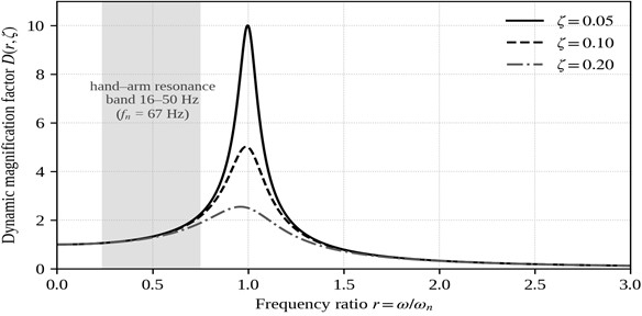
Fig. 8 shows the dynamic magnification factor (, ) for = 0.05, 0.10 and 0.20. For the reference design, the 16-50 Hz band associated with pronounced hand–arm resonant response [19] corresponds to = 0.24-0.75, where ≤ 2.14 for = 0.10. The excitation severity number of the reference case is = /() = 0.072 at = 30 m/s2, so that ≤ 0.154 within this band and the angular stability factor is ≥ 6.5. Even for sustained excitation exactly at resonance ( = 1), = 0.72, 0.36 and 0.18 for = 0.05, 0.10 and 0.20 respectively, i.e. = 1.4-5.6, and the criterion of Eq. (19) is satisfied throughout. The damping ratios considered here are scenario values rather than experimentally identified properties of the latch. At exact resonance, Eq. (19) reduces to /(2) < 1, so that the preload-free reference case is dynamically stable only when > /2. For the reference excitation severity = 0.072, the critical damping ratio is = 0.036. Thus, the lowest analysed value = 0.05 remains above the theoretical stability threshold, whereas a nearly undamped degraded mechanism with < 0.036 could reach the disengagement boundary under sustained resonant excitation. This result identifies damping as an additional parameter to be determined during prototype modal testing. The corresponding quasi-static rotation / = 0.0072 rad (0.41°) is small compared with = 0.10 rad (5.7°). The computed characteristics are summarised in Table 9.
Fig. 8Dynamic magnification factor D(r, ζ) of the pawl for three damping ratios; the shaded band marks the frequency-ratio interval corresponding to 16-50 Hz for the reference design (fn = 67 Hz)
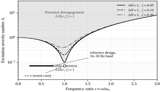
The complete picture is given by the dynamic stability map of the latch (Fig. 9): the curves 1 separate the region of stable retention from the region of potential disengagement in the (, ) plane. The reference operating segment ( = 0.072, = 0.24-0.75) and the worst-case resonance point lie deep inside the stable region for all three damping ratios. At resonance with = 0.05, disengagement of the preload-free reference model would require ≥ 0.1, corresponding to a harmonic acceleration amplitude ≥ 42 m/s2 sustained exactly at . This value should not be interpreted as a direct occupational-exposure threshold, because is the unweighted single-frequency acceleration amplitude applied to the latch housing, whereas Refs. [19, 20] concern hand-arm biodynamic response and transmitted vibration. The comparison therefore serves only to identify the resonance sensitivity of the latch model; prototype measurements are required to establish the actual excitation spectrum at the working head. Away from resonance, the admissible increases rapidly.
Fig. 9Dynamic stability map of the self-locking latch: boundaries ΛD(r, ζ) = 1 for ζ = 0.05, 0.10 and 0.20; the shaded region above the boundaries corresponds to potential disengagement. The thick segment marks the reference design (Λ = 0.072) over the 16-50 Hz band; the open circle marks sustained excitation at resonance
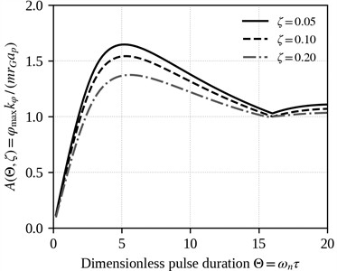
Figs. 8 and 9 describe Case B. The corresponding boundaries for the complete formulation, Eq. (22), were obtained by integrating the complementarity model with an explicit fourth-order Runge-Kutta scheme. The step was fixed at in dimensionless time, and the seated and free phases were switched on the conditions of Eq. (20) and on the sign of q. For the harmonic case the response was integrated over 90 excitation cycles and the peak taken over the last 35 % of the record. The scheme reproduces the closed-form Case B results to five significant figures. It returns the resonant amplitude and the peak shock amplification = 1.647, 1.542 and 1.374 at = 5.2-5.5 for = 0.05, 0.10 and 0.20, consistent with published response spectra for half-sine impact pulses [27].
Table 7Critical severity number Λcrit for harmonic excitation, Case C at Π = 3.33 compared with Case B
= / | Case B, = 0.10 | Case C, = 0.05 | Case C, = 0.10 | Case C, = 0.20 |
0.25 | 0.939 | 3.937 | 3.978 | 4.058 |
0.50 | 0.757 | 4.102 | 4.146 | 4.233 |
0.75 | 0.463 | 4.338 | 4.386 | 4.486 |
1.00 | 0.200 | 4.597 | 4.652 | 4.764 |
1.50 | 1.286 | 5.164 | 5.232 | 5.370 |
2.00 | 3.027 | 5.790 | 5.871 | 6.037 |
Two features of Table 7 change the qualitative picture. The Case C boundary is between four and twenty-three times higher than the Case B boundary, and the gap is widest exactly at resonance. More importantly, the damping ratio has only a weak influence within the examined Case C range: at = 1 a factor of four in changes the boundary by 3.6 %. The reason is structural – a preloaded pawl is seated over most of the excitation cycle, so no resonant build-up can occur and the excursion is limited by the impulse delivered while exceeds . The critical damping ratio = /2 is therefore a property of Case B alone. The same effect moves the worst case away from resonance: in Case C the minimum of lies in the sub-resonant range ≈ 0.2-0.5, where the excitation is slow enough for the pawl to follow it quasi-statically after lift-off. Table 8 gives this minimum as a function of the preload number, together with the quasi-static bound obtained by requiring the static opening moment to exceed the preload plus the incremental restoring moment at full engagement.
Table 8Minimum of Λcrit over the frequency ratio, Case C, ζ = 0.05, e = 0
min | Quasi-static bound | Ratio | ||
0.10 | 0.709 | 0.50 | 1.10 | 0.64 |
0.25 | 0.854 | 0.50 | 1.25 | 0.68 |
0.50 | 1.109 | 0.50 | 1.50 | 0.74 |
1.00 | 1.602 | 0.35 | 2.00 | 0.80 |
2.00 | 2.616 | 0.35 | 3.00 | 0.87 |
3.33 | 3.937 | 0.20 | 4.33 | 0.91 |
10.0 | 10.625 | 0.10 | 11.00 | 0.97 |
Over the whole range examined the computed boundary never falls below 0.64 of the quasi-static bound, which supports a conservative algebraic screening bound requiring no further integration. Restoring the engagement-retention factor of Eq. (3), and recalling that multiplies the additive term only, the criterion for retention in Case C is:
valid over 0.1 ≤ ≤ 40, 0.05 ≤ ≤ 0.20, 0.1 ≤ ≤ 2 and = 0. For below about 0.1 the seating threshold ceases to protect the mechanism and Case B must be used. The transition is abrupt. At = 0.05 and = 1 the boundary rises from = 0.20 at = 0 to = 0.81 at = 0.1, so even a small installed preload raises the disengagement threshold by roughly a factor of four.
For the nominal set the preload number is = 3.33, so / = 0.022 under the harmonic excitation of Table 5 and 0.072 under the reference pulse. The seating Eq. (20) is satisfied throughout and the pawl does not leave its seat, so the peak rotation predicted by Case C is identically zero for both excitations. The rotations reported below for Case B describe the preload-free idealisation only. The informative indicator for the nominal configuration is therefore the lift-off acceleration of Eq. (21), which here gives = 1389 m/s2, about 142 g. Over the parametric domain of Table 5 the indicator is far less comfortable. The ratio is maximised by the heaviest pawl with the largest mass-centre offset, combined with the smallest preload force and the shortest spring lever arm. That corner, = 0.15 kg, = 0.030 m, = 50 N and = 0.015 m, gives = 167 m/s2. Against the bounding pulse = 150 m/s2 the ratio reaches 0.90, so the no-lift-off margin falls from 13.9 at the nominal point to 1.11 at the corner. This identifies the preload moment , rather than the damping ratio, as the parameter that governs the design.
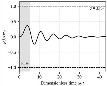
The shock response is summarised in Fig. 10. Fig. 10(a) gives the dimensionless amplification of the peak pawl rotation as a function of the half-sine pulse duration . The response is impulse-limited for short pulses. It reaches maxima of 1.65, 1.54 and 1.37 for = 0.05, 0.10 and 0.20 at ≈ 5.2-5.6, that is ≈ 12-13 ms for the nominal , and tends to the quasi-static value A → 1 for long pulses. For the worked example and = 100 m/s2, the shock severity number is 0.24 and the peak rotation at the most unfavourable pulse duration is = 0.037 rad = 0.37, shown in Fig. 10(b). This gives 2.7 for = 0.10 and 2.5 for = 0.05, again with the stabilising preload and tractive load neglected. Even at the bounding value of the parametric domain, = 150 m/s2 with the same stiffness and geometry, the peak rotation stays below 0.56.
Fig. 10Response of the pawl to a half-sine shock pulse: a) dimensionless peak-rotation amplification AΘ,ζ versus dimensionless pulse duration Θ=ωnτ; b) time history of the normalized rotation φ(t)/φcr for the reference parameter set at the most unfavourable pulse duration (Θ= 5.4, ζ = 0.10, ap = 100 m/s2)
a)
b)
Table 9Computed dynamic characteristics for the reference parameter set of Table 5 (preload threshold and tractive load neglected)
Quantity | Value |
Natural frequency (reference / parametric domain) | 66.9 Hz / 13-165 Hz |
Frequency ratio for the 16-50 Hz band | 0.24-0.75 |
Excitation severity number ( = 30 m/s2) | 0.072 |
and in the 16-50 Hz band ( = 0.10) | ≤ 0.154; ≥ 6.5 |
at resonance = 1, = 0.05 / 0.10 / 0.20 | 0.72 / 0.36 / 0.18 |
at resonance = 1, = 0.05 / 0.10 / 0.20 | 1.4 / 2.8 / 5.6 |
Critical damping ratio at resonance, = /2 | 0.036 |
Preload lift-off margin /(), harmonic / shock | 46 / 14 |
Peak shock amplification (, = 0.10) | 1.54 at ≈ 5.4 |
Peak shock rotation ( = 100 m/s2) | 0.037 rad = 0.37 |
Shock stability factor , = 0.10 / 0.05 | 2.7 / 2.5 |
Table 10Critical shock severity Λp,crit for the half-sine pulse, ζ = 0.10
= | , Case B | , Case B | , Case C at = 3.33 |
1.0 | 0.536 | 1.865 | 7.418 |
2.0 | 0.998 | 1.002 | 5.319 |
3.0 | 1.323 | 0.756 | 4.704 |
5.25 | 1.542 | 0.648 | 4.236 |
8.0 | 1.439 | 0.695 | 4.057 |
15.0 | 1.045 | 0.957 | 3.976 |
40.0 | 1.005 | 0.995 | 4.283 |
The worst pulse duration in Case C is again not the one that maximises the oscillator amplification. In Case B the peak occurs at ≈ 5.2, whereas the minimum of in Case C lies near ≈ 15. Those are pulses long compared with the natural period, for which the pawl remains off its seat long enough to approach the quasi-static excursion.
Clearance-induced impacts are representable within Eq. (22) through the coefficient of restitution of the -seating law. Raising e allows the pawl to rebound and to accumulate rotation over successive cycles, with the effect shown in Table 11.
Table 11Effect of the restitution coefficient on the critical severity number, Case C, Π = 3.33, ζ = 0.05
= 0.20 | = 0.35 | = 0.50 | = 0.75 | = 1.00 | Minimum | |
0.0 | 3.937 | 3.986 | 4.102 | 4.338 | 4.597 | 3.937 |
0.3 | 4.015 | 3.945 | 3.899 | 3.862 | 3.863 | 3.862 |
0.6 | 4.062 | 3.755 | 3.379 | 3.333 | 3.333 | 3.333 |
0.9 | 4.086 | 3.333 | 3.333 | 3.333 | 3.333 | 3.333 |
As the restitution coefficient increases the disengagement threshold falls towards the lift-off threshold = = 3.33 itself, and for ≥ 0.6 the two coincide over most of the frequency range. Vibro-impact therefore does not lower the threshold at which the pawl first leaves its seat, but it removes the post-lift-off reserve, which for the reference design is about 18 % of the threshold. Under sustained vibration with hard, lightly damped contacts the governing criterion reduces to the seating condition < . For shock loading the same computation gives = 4.19 at = 5.25 and 3.94 at = 15 for every value of e between 0 and 0.9, since a single pulse produces one excursion; the shock results of Table 10 are thus insensitive to the vibro-impact assumption. Two mechanisms remain outside the model: impacts against the walls of the pawl slot, which form a two-sided constraint, and broadband random excitation distributed over the modes of Table 3.
These results are consistent with the effect already established on static grounds. Locating the catch assembly on the non-working upper part of the shoe preserves the braking properties of the sole, while the self-tightening geometry prevents release under tractive load. The dynamic model provides a quantitative design margin for the preload-free limiting case. Within the 16-50 Hz comparison band the worked example retains an angular stability factor of at least 6.5 for = 0.10. At exact resonance the margin becomes damping-dependent, and the theoretical disengagement boundary is reached only when falls below 0.036 for that excitation severity. Under half-sine shock loading the corresponding shock stability factor is 2.7 for = 0.10 at the most unfavourable pulse duration. These quantities are model-based margins for Case B and not occupational-exposure thresholds, and they require prototype-measured excitation spectra for operational validation.
Because the harmonic response is governed solely by the dimensionless group (, , ), the sensitivity of the margins to the individual physical parameters enters only through and the natural frequency . The severity number is first-order proportional to the pawl mass, the mass-centre offset and the base-acceleration amplitude, and inversely proportional to the torsional stiffness and the engagement-loss angle, whereas scales as the square root of stiffness over inertia. A ±20 % change in any single governing parameter therefore alters by at most ±20 % and by at most about ±10 %. The resonant angular stability factor varies as /, so its reference value of 2.8 at = 0.10 ranges between roughly 2.3 and 3.5 and stays above unity. The natural frequency remains within about 60-75 Hz, so the 16-50 Hz comparison band stays sub-resonant and the in-band stability factor of at least 6.5 is preserved. The margins of Case B are thus robust to parameter uncertainties of this order.
Because every criterion is linear in , the consequence of an unknown grip-to-pivot amplification can be stated exactly. Table 12 gives the value of at which each criterion is reached for the reference set.
Table 12Amplification factor β at which each criterion is reached
Criterion | Excitation | at the limit |
Case B, resonance, = 0.10 (upper-bound idealisation) | = 30 m/s2 | 2.8 |
Case A, loss of seating, = | = 100 m/s2 | 13.9 |
Case C, disengagement, worst pulse duration | = 100 m/s2 | 16.6 |
Case A, loss of seating, = | = 30 m/s2 | 46.3 |
Case C, disengagement, worst frequency ratio | = 30 m/s2 | 54.7 |
Case A, loss of seating, worst corner of Table 5 | = 150 m/s2 | 1.11 |
The table reorders the priorities of the study. The preload-free idealisation loses its margin at an amplification of only 2.8, which is plausible for a hand-held tube near one of its own modes, and that is why Case B is labelled an idealisation. The nominally preloaded latch tolerates about 14 under the reference shock. At the worst corner, the lift-off threshold is reached at = 1.11. Thus, amplification exceeding approximately 11 % relative to the assumed value = 1 would cause loss of seating under the bounding pulse.
Applying the decision rule Eq. (30) with = 10.9 % places the acceptance limit on the point estimate at / < 0.822, with the outcome shown in Table 13.
Table 13Conditional guard-banded no-lift-off screening at β = 1 (excitation and transfer uncertainties excluded)
Configuration | /, point estimate | Upper bound, Eq. (30) | Decision |
Reference set, = 30 m/s2 | 0.022 | 0.026 | Passes the conditional screen |
Reference set, = 100 m/s2 | 0.072 | 0.088 | Passes the conditional screen |
Worst corner of Table 5, = 150 m/s2 | 0.900 | 1.096 | Fails the conditional screen |
At the worst corner, acceptance requires < 5.56 %. With only known exactly, the remaining combined uncertainty is 7.35 %, so the criterion is not satisfied. If both and are known exactly, the remaining combined uncertainty is 5.39 %, which gives an upper bound of 0.997 and therefore only marginally satisfies the criterion. This narrow margin would disappear once the uncertainties of the excitation amplitude and the grip-to-pivot transfer factor are included. The present evidence therefore does not justify acceptance of the corner configuration.
A robust remedy is to increase the preload moment from 0.75 to at least 0.82 N·m. Reducing the uncertainty of alone is insufficient; both and , together with the applied acceleration and transfer factor , must be characterised before a measurement-based decision can be made.
The framework is analytical, no measurement of any parameter was carried out for this study, and the framework has not been experimentally validated. Every quantity reported above is a model prediction conditional on the parameter values of Table 5, on the uncertainties assigned in Table 6 and on the assumption = 1. None is an operational safety limit. The damping ratio, the torsional stiffness and the critical opening angle rest on design estimates, and the friction coefficient on a literature interval. The influence of each is now bounded: governs Case B directly and weakly affects the computed Case C boundary, enters only the static Eq. (6), and cr cancels in the decision variable of Eq. (16). The validation roadmap follows from the analysis itself and is ranked by the value of each measurement. First, the transfer from grip to pivot over 5-100 Hz, from two accelerometers on an instrumented fork, because Table 12 shows that this quantity can change the margin from large to near its threshold. Second, the installed spring data, , together with the force–displacement curve and the lever arm over the engagement angle, from which the preload number and the correction of Eq. (28) follow. Third, the modal frequencies of Table 3 under the actual grip conditions. Fourth, the damping ratio, which ranks last because Table 7 shows that a fourfold change in it moves the Case C boundary by less than 4 %. Comparison of measured peak rotations with the Case C predictions of Eq. (22) is the closing step. Prototype testing of the assembled latch under the spectra of IEC 61373 remains necessary before any indicator reported here is used as a design value.
5. Conclusions
1) The engagement geometry of a spring-loaded pawl latch has been formulated explicitly. The critical opening angle follows from the engagement depth and the engagement radius, Eq. (2), and a retention factor collects the wear, tolerance and elastic-approach allowances, so that the angle is traceable to drawing dimensions rather than assumed.
2) The contact forces and moments have been derived for the locked and the incipient-opening configurations with a stated sign convention. The equivalent-wedge condition is the plane-flank limit of the general Eq. (6). For the cylindrical catch pin of the device the retention condition, exact within the planar rigid-contact model, is , Eq. (7), in which is the angle between the two contact radii and is the same angle that fixes the critical opening angle; the wedge form is non-conservative whenever exceeds the contact position .
3) The latch has been treated as a unilateral-contact system. Three cases have been separated and are reported separately: the seated latch, the preload-free oscillator retained as an upper-bound idealisation, and the seated latch with a lift-off threshold, formulated as the linear complementarity problem (22).
4) A preload number has been introduced. The decision variable is the ratio of the peak inertial moment to the preload moment; it depends on four measurable quantities and not on the stiffness or the engagement angle, and it carries a smaller relative uncertainty than either severity measure separately.
5) Numerical integration of the complementarity model supports the conservative algebraic screening bound over the ranges examined. Within these ranges the damping ratio moves the boundary by less than 4 % and the governing frequency ratio is sub-resonant, so the critical damping ratio obtained for the preload-free case is a property of that idealisation alone.
6) For sustained vibration with a restitution coefficient above about 0.6 the disengagement threshold collapses onto the seating criterion , so the post-lift-off reserve should not be relied upon in design. Within the examined single half-sine pulse model, the predicted shock response is weakly sensitive to the assumed restitution coefficient.
7) The explicitly defined Euler-Bernoulli/Rayleigh shaft model gives a calculated first bending-frequency range of 3.2-62.0 Hz across the stated boundary and tip-mass cases. This range brackets the 16-50 Hz comparison band and demonstrates that the grip-to-pivot transfer factor cannot be fixed at unity without measurement. The elastic-yield estimate indicates that purely elastic shaft twist cannot independently produce the full release rotation; a smaller torsional contribution remains unresolved until the torsional transfer path is measured. The grip-to-pivot amplification is therefore the measurement of highest value, ahead of the damping ratio.
8) All numerical results are model predictions conditional on the parameter values assumed in Table 5 and on the amplification factor being unity. They are screening indicators for design comparison and not operational safety limits. The framework transfers to other pivoted spring-loaded pawl mechanisms provided that retention is characterised by a critical opening angle, that the seat is a one-sided constraint, and that a preload number and an amplification factor can be established for the mechanism concerned; these conditions, rather than the geometry, delimit its applicability.
References
-
L. Xu, “Safety Scotch block for railway,” Chinese Utility Model CN 2688572, 2005.
-
C. Zi, “Safety theftproof auto-locking Scotch-block for train yard rail,” Chinese Utility Model CN 2157102 Y, 1994.
-
A. H. Stockhausen and W. G. Brinkworth, “Scotch-block for stopping runaway railway or tramway vehicles,” U.S. Patent 1 116 153 A, 1914.
-
W. Maddox and B. Cobb, “Wheel chock for chocking railroad car wheel,” U.S. Patent 5 685 397 A, 1997.
-
M. Talipov, “Computational modeling and analysis of mechanical power consumption in train assemblers’ work,” in Proceedings of the International Conference on Applied Innovations in IT (ICAIIT), Vol. 13, No. 2, pp. 419–426, 2025, https://doi.org/10.25673/120513
-
Q. X. Ergashev and R. Akbarli, “Assessment of vehicle-induced acoustic and vibrational impacts on the human body,” Vibroengineering Procedia, Vol. 62, pp. 252–260, Jun. 2026, https://doi.org/10.21595/vp.2026.26359
-
“Mechanical vibration – measurement and evaluation of human exposure to hand-transmitted vibration – part 1: general requirements,” ISO 5349-1:2001, Geneva, Switzerland, 2001.
-
“Mechanical vibration – measurement and evaluation of human exposure to hand-transmitted vibration – part 2: practical guidance for measurement at the workplace,” International Organization for Standardization, Geneva, Switzerland, 2001.
-
“Directive 2002/44/EC of the European Parliament and of the Council on the minimum health and safety requirements regarding the exposure of workers to the risks arising from physical agents (vibration),” Official Journal of the European Communities, 2002.
-
V. L. Veitz, N. I. Kolchin, and A. M. Martynenko, “Some questions of the dynamics of self-locking mechanisms,” Journal of Mechanisms, Vol. 4, No. 2, pp. 93–104, Feb. 2005, https://doi.org/10.1016/0022-2569(69)90020-2
-
A. A. Goncharov and A. A. Goncharov, “Study of the influence of geometric parameters of elements upon self-locking of free running wedge mechanisms,” Journal of Machinery Manufacture and Reliability, Vol. 43, No. 1, pp. 14–21, Feb. 2014, https://doi.org/10.3103/s1052618814010075
-
A. A. Goncharov and A. A. Goncharov, “Self-braking of free-wheel mechanisms,” Russian Engineering Research, Vol. 36, No. 5, pp. 339–344, Jun. 2016, https://doi.org/10.3103/s1068798x16050063
-
C.-H. Lee and A. A. Polycarpou, “Static friction experiments and verification of an improved elastic-plastic model including roughness effects,” Journal of Tribology, Vol. 129, No. 4, pp. 754–760, Oct. 2007, https://doi.org/10.1115/1.2768074
-
J. Hu, L. Xu, S. Guo, Y. Sun, and G. Li, “Study on inertia load resistance analysis method of light truck door latch,” Applied Sciences, Vol. 12, No. 9, p. 4171, Apr. 2022, https://doi.org/10.3390/app12094171
-
K. Friedman, K. Bui, and J. Hutchinson, “Door latch failure risk identification using virtual testing methods,” ASCE-ASME Journal of Risk and Uncertainty in Engineering Systems, Part B: Mechanical Engineering, Vol. 4, No. 3, p. 031001, Sep. 2018, https://doi.org/10.1115/1.4037725
-
Y. Liu, Z. Lin, and K. Zhao, “Simulation and experimental research on dynamic characteristics of overrunning clutch,” Journal of Vibroengineering, Vol. 21, No. 3, pp. 570–586, May 2019, https://doi.org/10.21595/jve.2018.20035
-
S. Divi et al., “Latch-based control of energy output in spring actuated systems,” Journal of the Royal Society Interface, Vol. 17, No. 168, p. 20200070, Jul. 2020, https://doi.org/10.1098/rsif.2020.0070
-
Y. Dong et al., “Performance of the transmission parking mechanism of a battery electric vehicle simulated with Adams software,” Automotive Innovation, Vol. 1, No. 2, pp. 114–121, Jun. 2018, https://doi.org/10.1007/s42154-018-0023-y
-
X. S. Xu, D. E. Welcome, T. W. Mcdowell, C. Warren, and R. G. Dong, “An investigation on characteristics of the vibration transmitted to wrist and elbow in the operation of impact wrenches,” International Journal of Industrial Ergonomics, Vol. 39, No. 1, pp. 174–184, Aug. 2008, https://doi.org/10.1016/j.ergon.2008.05.006
-
X. S. Xu, R. G. Dong, D. E. Welcome, C. Warren, T. W. Mcdowell, and J. Z. Wu, “Vibrations transmitted from human hands to upper arm, shoulder, back, neck, and head,” International Journal of Industrial Ergonomics, Vol. 62, pp. 1–12, Jul. 2016, https://doi.org/10.1016/j.ergon.2016.07.001
-
S. Mansour, F. Rizzo, N. I. Giannoccaro, A. La Scala, M. F. Sabbà, and D. Foti, “Essential dynamic characterization of a historical bridge: integrated experimental and numerical investigations,” Journal of Civil Structural Health Monitoring, Vol. 14, No. 1, pp. 85–102, Dec. 2023, https://doi.org/10.1007/s13349-023-00744-y
-
F. Rizzo et al., “Construction and dynamic identification of aeroelastic test models for flexible roofs,” Archives of Civil and Mechanical Engineering, Vol. 23, No. 1, Oct. 2022, https://doi.org/10.1007/s43452-022-00545-y
-
F. Rizzo, “Investigation of the time dependence of wind-induced aeroelastic response on a scale model of a high-rise building,” Applied Sciences, Vol. 11, No. 8, p. 3315, Apr. 2021, https://doi.org/10.3390/app11083315
-
“Railway Applications – Rolling Stock Equipment – Shock and Vibration Tests,” International Electrotechnical Commission, London, 2010, https://doi.org/10.3403/30195772
-
R. O. Curadelli, J. D. Riera, D. Ambrosini, and M. G. Amani, “Damage detection by means of structural damping identification,” Engineering Structures, Vol. 30, No. 12, pp. 3497–3504, Jul. 2008, https://doi.org/10.1016/j.engstruct.2008.05.024
-
P. E. Tapia-González and D. F. Ledezma-Ramírez, “Experimental characterisation of dry friction isolators for shock and vibration,” Journal of Low Frequency Noise, Vibration and Active Control, Vol. 36, No. 1, pp. 83–95, Mar. 2017, https://doi.org/10.1177/0263092317693509
-
T.-Y. Tsai, C.-L. Yeh, Y.-S. Lai, and R.-S. Chen, “Response spectra analysis for undamped structural systems subjected to half-sine impact acceleration pulses,” Microelectronics Reliability, Vol. 47, No. 8, pp. 1239–1245, Oct. 2006, https://doi.org/10.1016/j.microrel.2006.07.096
About this article

The authors have not disclosed any funding.
The datasets generated during and/or analyzed during the current study are available from the corresponding author on reasonable request.
Miraziz Talipov: conceptualization, methodology, formal analysis, visualization, writing-original draft, writing-review and editing. Alexander Kolesnikov: writing-review and editing.
The authors declare that they have no conflict of interest.

