Abstract
Rail vehicle suspension is responsible for providing proper running behavior and safety. In order to keep appropriate safety level, low wear of wheels and rails, and also regular transport services, it should be monitored. The paper deals with the problem of suspension fault detection by introducing methods implemented in rail and track monitoring system developed within the framework of the project: ‘MONIT – Monitoring of Technical State of Construction and Evaluation of its Lifespan’. The approach to suspension fault detection presented in the paper consists of three levels, especially the method based on the multidimensional analysis of acceleration signals statistical parameters.
1. Introduction
Vibration-based condition monitoring techniques have found application in many branches of engineering due to high availability of measuring devices (e.g. accelerometers, data acquisition units) and the advancement of signal processing methods. The monitoring systems based on vibration measurement can be well suited to the certain machine or structure fault detection and/or condition assessment. Since the monitoring systems are employed to reduce costs of malfunctions, they are especially demanded as means of rising safety level. However, despite the progress in the field of signal processing methods, there are still difficulties in proper condition assessment of certain objects, which arise from the nature of their dynamic behavior and phenomena associated with its operation. This kind of obstacles is particularly apparent in the case of a rail vehicle’s suspension monitoring. At present, numerous components of the rail vehicles, especially high-speed trains, are subject to continuous monitoring. The third-party manufacturers provide complex monitoring systems such as Multilog IMx-R [1], which enables bogie condition monitoring: detection of flat wheels, bogie stability, axle box temperature, etc. Unfortunately, any sufficient, commercial suspension monitoring system for the rail vehicles has not been delivered yet. The reason of the actual state of affairs is lack of the regulations imposing on the manufacturers or the rail operators installation of such a system and difficulties in defining damage detection method.
The suspension plays a major role in vehicle dynamics. Particularly in case of rail vehicles, it is a complex system of many links, spring and damping elements, which form primary (connects wheelsets with bogies) and secondary suspension (connects bogies with body). From the point of view of running safety, it is important to check suspension condition regularly, since it is a system providing proper dynamic behavior and has a strong influence on the generation of the forces in wheel-rail contact patch.
The failures of springs and dampers may change vehicle’s behavior, what in turn may lead to accelerated wear of wheels and rails. In more dangerous case, suspension damages may rise the risk of derailment due to improper wheel load distribution, and thus cause wheelset lateral displacement out of designed limit.
In order to monitor suspension condition, a new damage detection method based on signal analysis in diagnostic space is proposed. The method is defined for the rail vehicle and track monitoring system developed within the framework of the project: “MONIT – Monitoring of Technical State of Construction and Evaluation of its Lifespan”.
The following chapters of the paper present the idea of the rail vehicles and track monitoring system and application of damage detection method to data acquired by the system.
2. State of the art
In recent years relevant papers have been published on a rail vehicle suspension fault detection. The significant number of methods utilizes mathematical description of the vehicle model. These ‘model-based’ methods transform vehicle’s equations of motion into the form of state space representation. The changes of the model’s parameters (stiffness or damping) are reflected in the state space. Deviations of the parameters – faults in suspension elements – may be detected by means of Kalman filter as well as its variations [2-6]. Non-Kalman estimation of the vehicles’ faulty states have been published in [7-10]. In publications [11-13] a multiple-model approach is introduced, where each model represents possible vehicle mode. Although model-based methods proved its diagnostic usefulness in simulation studies, they require precise suspension and inertial parameters’ values. Those parameters are not always available since rolling stock manufacturers may not reveal them. The results of the model-based methods are also highly depended on accuracy of the vehicle model [14].
Another group of methods rely on signal processing techniques and do not involve mathematical model in the fault detection process. A model-less methods taking into consideration relations between specific motions of a vehicle’s bogie (angular and translational) are proposed in [15-17]. In [18] Multi-block Partial Least Squares approach is applied to build the statistical model using the historical normal operating data. A novel class of stochastic ARX-type models capable of representing a faulty state of vehicle is presented in [19].
Although there is a little information on implementation of the mentioned above methods in the rail vehicles monitoring system prototypes [7, 15], the automotive industry managed to develop methods for shock absorbers testing such as BOGE or EUSAMA [20]. However, these methods, due to their assumptions, are only designed for the test rigs. The mentioned in situ tests are characterized by the known excitation (displacement/force, frequency) acting on an extortion plate which, in turn, enables to assess condition of the shock absorber.
3. The approach to suspension fault detection
Condition assessment or even fault detection and identification of suspension is a complex task. One of the main difficulties in recognition of its condition or damage detection is strong dependence of the vehicle’s dynamic responses (vibration) on the excitation. The main sources of the excitation are track irregularities and track geometry. In some circumstances the excitation may be sufficient, i.e. of the certain magnitude and frequency, to cause the vehicle response as if there was a damage of suspension. Another issue is ‘direction’ of the response − an increase or decrease of the recorded measurement signal values. The damages of damper or spring usually have different influence on the recorded signals and also depend on the frequency of excitation, what is shown in section 4. Dealing with these variable effects required developing a new damage detection method basing on signal analysis in diagnostic space (Section 3.4).
The fault detection technique for the rail vehicle monitoring system has to deal not only with the unknown technical state of suspension, but also with changing operating conditions such as vehicle speed or track geometry and irregularities. The latter conditions can be only estimated during vehicle passage on the analyzed rail track section.
3.1. Assumptions for the monitoring system
The operating principle of the rail vehicle and track monitoring system is the on-line analysis of acceleration signals recorded in selected points on a vehicle. These points are obtained from the rail standards such as EN 14363 [21] or UIC 518 [22]. The standards define requirements for the rail vehicles from the point of view of their dynamic behavior. Suspension damages – deviations from nominal suspension parameters – affect dynamic responses of vehicles. The reference measures are, according to [21, 22], values of acceleration signals and forces on the wheelsets. However, the latter is difficult to measure in a rail vehicle-track mechanical system and is carried out mainly for homologation purpose.
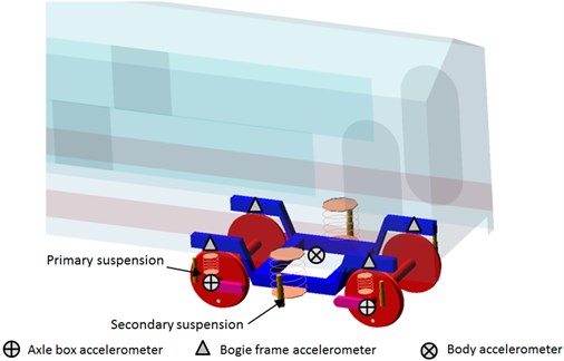
In order to measure acceleration for dynamic behavior assessment – the accelerometers should be located on (Fig. 1):
– axle bearing housing (axle box),
– bogie frames,
– vehicle body.
Fig. 1Location of the accelerometers
The acceleration signals from the above locations are used for running behavior, safety and comfort assessment [21, 22]. Nonetheless, its use may be extended to condition monitoring (damage detection) of:
– rail track,
– primary suspension,
– secondary suspension.
A study of a rail vehicle condition should be carried out with respect to track. The track and vehicle cannot be considered separately if dynamic properties are in our focus, due to interaction between these two subsystems through contact patch. This fact imposes necessity of continuous track condition monitoring in order to assess properly vehicle’s suspension condition.
Monitoring and fault detection procedure implemented in the system can be divided into three levels:
– identification of track condition – the first level;
– comparison of acceleration parameters, computed during measurement, with normative ones [21, 22] − the second level;
– analysis of the signals in diagnostic space − the third level.
For suspension monitoring purpose (damage detection) a new method has been developed – the third level. It is intended to deal with variable influence of damages on recorded measuring signals. This approach uses selected statistical parameters of acceleration signals, similarly as in the case of the second level, but the parameters are further processed forming diagnostic space. The detailed information on the method is presented in Subsection 3.4.
3.2. Track condition monitoring procedure – the first level
Track condition monitoring is the system’s feature that enables obtaining qualitative information on track sections and facilitates suspension condition assessment process. Track condition is understood as a level of rails’ vertical and lateral irregularities, as well as other track’s imperfections, e.g. track centerline irregularity. These irregularities are, together with track geometry, one of the main sources of vehicles vibrations.
Evaluation of track condition is carried out by analyzing acceleration signals recorded on the axle boxes. The signals are used to compute a dimensionless track quality indicator (Eq. (1)) – a measure of track condition, proposed in [23, 24]. The idea of the track quality indicator is derived from Sperling’s ride quality index [25].
The basic quality indicator – a measure of track condition is based on power spectral density of acceleration signals. However, this algorithm is not sufficiently fast for continuous monitoring and has been simplified achieving form of Eq. (2) which is implemented in the system – :
where: – angular frequency [rad/s], – power spectral density of acceleration signal [m2s-3], 2.642, value set on the basis of the numerical research, 0.225, value set on the basis of the numerical research, – values of filtered acceleration signal, – period of measurement.
Values of track quality indicator depend on the wheelset acceleration due to kinematic excitations, thus according to Newton’s second law also on forces exerted in the wheel-rail contact. The parameter (Eq. (2)) represents values of the acceleration signals sampled at 15 kHz and filtered with 100 Hz low-pass filter. Acceleration signals sampled at such a high frequency can be used further to investigate for corrugation – a specific track wear [24]. The constant (Eq. (1)) was adjusted to 2.642 so the value is from range of 0-5.
Proposed classification of track quality indicator is presented in Table 1 [26]. However, as the research [26] has shown, the values of track quality indicator may vary significantly for speed range of 130-150 km/h and above. It is important to define indicator for certain speed values. The modified indicator’s value (Eq. 2) was set to 0.225 to match dependency on vehicle speed of the basic indicator.
The classification is different from normative description of track quality based on irregularities’ geometric height [21, 22]. Instead we obtain information on track in a form of processed dynamic responses (accelerations) of the wheelsets.
Table 1Track quality indicator Wt classification [26]
Class | Track condition | Value |
1 | Very good | < 1.0 |
2 | Good | 1.0-1.5 |
3 | Acceptable | 1.6-2.5 |
4 | Bad | > 2.5 |
3.3. Vehicle suspension condition monitoring procedure – the second level
The second level of monitoring evaluates the compliance with the rail standards [21, 22] in terms of statistical parameters values of acceleration signals. The measures whose values cannot be exceeded during operation are RMS and zero-peak (percentile 99.85 %), Table 2.
The above thresholds are implemented in the monitoring system and are universal for any type of rail vehicle. Occurring damages or deterioration of suspension elements could affect rail vehicle dynamic behavior and, due to that fact, the normative requirements may not be met.
Suspension condition assessment based on the above comparison of obtained values of acceleration signals with normative ones shows some shortcoming. The dynamic response of rail vehicle depends on the sort of damage: stiffness or damping reduction, and the frequency of excitation which is composition of (on tangent track) speed and magnitude of rail irregularities. In certain condition – excitations due to e.g. track condition, the same suspension fault may result in the increase or in the decrease of acceleration values with respect to values recorded on the nominal vehicle. If the signal values are decreased due to the damage, the normative parameters will not be exceeded. This approach would not allow us detecting all possible faults but is helpful in rough verification of the compliance with standards [21, 22]. In order to overcome this disadvantage an additional fault detection method is proposed – the third level of monitoring.
Table 2Parameters’ limit values and filters’ cut-off frequencies
Measurement point location | Direction | Zero-peak [m/s2] | RMS [m/s2] |
Body | Lateral () | 2.5 0.410 Hz | 0.5 0.410 Hz |
Vertical () | 2.5 0.410 Hz | 0.75 0.410 Hz | |
Bogie frame | Lateral () | 10.9 10 Hz | 5 10 Hz |
Vertical () | 20 20 Hz | 7 20 Hz |
3.4. Diagnostic space – the third level
In this approach the faults which result in decrease of acceleration signal values can be indicated. It is possible since the third level is based on comparison of a distance between points in diagnostic space. The diagnostic space is, by assumption, multidimensional and these dimensions are the statistical parameters of acceleration signals.
For damage detection purpose we can distinguish specific points in the diagnostic space whose coordinates are the values of the statistical parameters. The reference point (Eq. (3)) is obtained for a vehicle in nominal condition and for certain speed. Its value is an arithmetic mean of values acquired from many passages on the same track section of known condition.
The reference point describing nominal condition of the vehicle can be expressed:
where, , ,..., – the following values of the coordinates (signal parameters) for the reference point and velocity .
During operation the monitoring system via measurements places the ‘current points’ , referring to current condition, in the diagnostic space (Eq. (4)):
where, , ,..., – the following values of the coordinates (parameters) for the current point and velocity , – the number of measurement.
Having the reference point and a point obtained during measurement (current point) for a certain speed, the inference on vehicle’s suspension condition is proceeded by comparison of the distance between and , calculated as Euclidean metric, with the limit distance , Eq. (5):
The simplified conception of the damage detection method is presented in Fig. 2.
The selection procedure of the statistical parameters is introduced in paper [27]. The idea of the procedure was to select those parameters which provided the largest values of distance between points collected from the simulation. The implemented damages in the rail vehicle model corresponded to those introduced in the experimental test, described in Section 4. After completion of the selection process the parameters included in Table 3 were used for the third level of monitoring.
Fig. 2The conception of suspension fault detection method
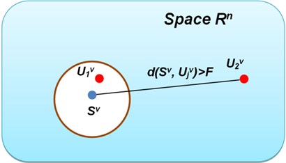
Since statistical parameters have different values (scales), the normalized ones are used. Coordinates values of current and reference point are divided by the corresponding values of the reference point. After this computation coordinates are (1, 1, 1).
The value can be acquired basing on statistical analysis of the nominal vehicle numerical analyses or experimental tests. The is set to be equal to the mean value of and two standard deviations of . The selection of the method was a trade-off between percentages of false alarms and percentages of improperly assessed samples as nominal condition [28].
Table 3Parameters used for damage detection at the third level
No. | Primary suspension | Secondary suspension |
1 | Signal energy | |
2 | Interquartile range (IQR) | |
3 | Zero-peak | Peak-peak |
4. Numerical study
The influence of the suspension damages was a subject of the studies presented in [28-30] which focused on the changes of vibration signals parameters’ values. The results of the simulation study presented herein are in the form of power spectral densities of acceleration signals, in order to investigate changes of dynamic responses caused by suspension damages. This study was performed in VI-Rail – multibody simulation software. The vehicle model adopted in numerical study represented a typical passenger four-axle wagon, comprised of the main elements:
– a body,
– two bogie frames,
– four wheelsets (S1002 wheel profile),
– suspension elements – springs, dampers and links.
The dynamic behavior of the rail vehicle related to running properties (e.g. stability) and safety is investigated in the low-frequency range, up to 50 Hz. This approach let us assume that the main inertial elements can be treated like rigid bodies, instead of incorporating more complex, flexible-body models [31].
The characteristic dimensions, inertial and stiffness parameters are presented in Table 4. The dampers of primary and secondary suspension have nonlinear characteristics.
Contact forces between wheel and rail are computed using Kalker’s FASTSIM procedure [32].
Track model represents tangent section with irregularities corresponding to a good level of maintenance, classified as QN1 according to [21]. The track has the normal rail gauge of 1435 mm with UIC60 profile. The track model is assumed to have rigid rails and does not have any flexible connection between rails and ballasts.
The aim of the simulation study was to compare the acceleration signals obtained from the ‘nominal’ and ‘damaged’ simulation model. Suspension damages were implemented as changes of damping and stiffness coefficients.
From many possible faults, two kinds of damages were chosen for further analysis which are identical with faults during experimental tests (Section 5):
– one primary spring stiffness reduction ,
– loss of one secondary damper .
Table 4The parameters of the passenger wagon model
Body | |
Length | 24 m |
Mass | 32000 kg |
Moment of inertia | 5,68∙104 kgm2 |
Moment of inertia , | 1.97∙106 kgm2 |
Distance between bolsters | 19 m |
Bogie | |
Base | 2.56 m |
Mass | 2615 kg |
Moment of inertia | 1722 kgm2 |
Moment of inertia | 1476 kgm2 |
Moment of inertia | 3067 kgm2 |
Wheel diameter | 0.92 m |
Wheelset mass | 1503 kg |
Moment of inertia , | 810 kgm2 |
Moment of inertia | 112 kgm2 |
Primary suspension | |
Longitudinal stiffness | 7.41∙105 N/m |
Lateral stiffness | 7.41∙105 N/m |
Vertical stiffness | 8.78∙105 N/m |
Damping series stiffness | 6.0∙105 N/m |
Secondary suspension | |
Spring longitudinal stiffness | 1.6∙105 N/m |
Spring lateral stiffness | 1.6∙105 N/m |
Spring vertical stiffness | 4.3∙105 N/m |
4.1. Results of primary suspension stiffness reduction
Fig. 3 depicts power spectral densities of acceleration signals recorded in lateral direction, on a bogie frame. It can be seen in Fig. 3 that lateral vibrations of the model’s bogie are only slightly affected by stiffness reduction. In vertical direction (Fig. 4) the changes of acceleration PSD are substantial and it can be concluded that stiffness reduction attenuates acceleration values in the frequency range of ca. 8-15 Hz. This frequency range is crucial from the point of view of bogie dynamics due to covering natural frequencies of the wheelsets and the bogie frame.
4.2. Results of secondary suspension damping reduction
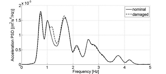
For secondary suspension condition assessment, it is assumed that measuring signals are recorded on a body, above bogie frame’s center. Similarly, to stiffness reduction case, PSD of the lateral measuring signal is practically unchanged compared to results from the nominal model (Fig. 5). Nevertheless, in case of the vibration signals from vertical direction, an abrupt increase of power spectral density for 0.8 up to 1.5 Hz is observed (Fig. 6). This frequency range refers to the body’s bouncing mode frequency.
Fig. 3Power spectral density of acceleration signal recorded in lateral direction on the wagon model’s bogie in nominal condition and reduced primary suspension stiffness at one wheel of leading wheelset, v= 80 km/h
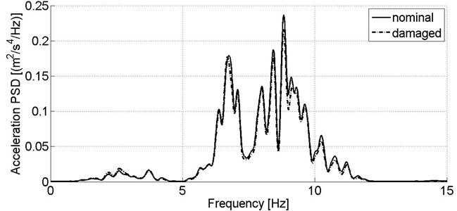
Fig. 4Power spectral density of acceleration signal recorded in vertical direction on the wagon model’s bogie in nominal condition and reduced primary suspension stiffness at one wheel of leading wheelset, v= 80 km/h
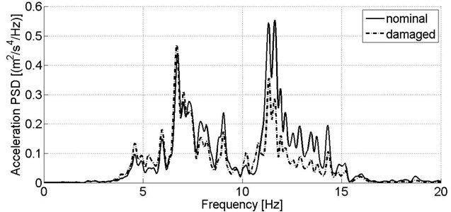
Fig. 5Power spectral density of acceleration signal recorded in lateral direction on the wagon model’s body in nominal condition and reduced secondary suspension damping of one damper, v= 80 km/h
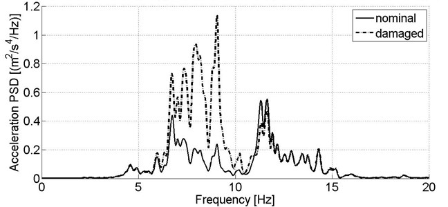
Although acceleration sensor located on the body is a primary source of information on secondary suspension condition, the damper fault in simulation study affects strongly vibration of the bogie frame in frequency range of ca. 6-10 Hz, what is observed for both directions of signals acquisition (Fig. 7-8).
It can be seen in Fig. 3-8 that suspension damages change dynamic responses of the rail vehicles and we should expect influencing its running behavior (primary suspension) and comfort (secondary suspension).
Fig. 6Power spectral density of acceleration signal recorded in vertical direction on the wagon model’s body in nominal condition and reduced secondary suspension damping of one damper, v= 80 km/h
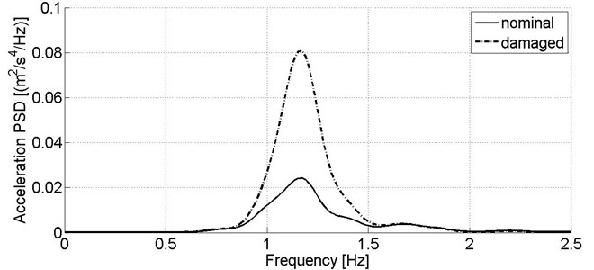
Fig. 7Power spectral density of acceleration signal recorded in lateral direction on the wagon model’s bogie in nominal condition and reduced secondary suspension damping of one damper, v= 80 km/h
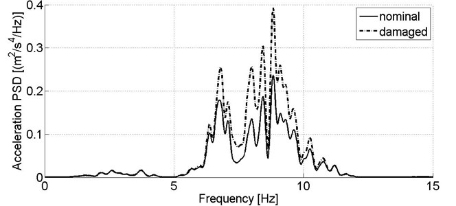
Fig. 8Power spectral density of acceleration signal recorded in vertical direction on the wagon model’s bogie in nominal condition and reduced secondary suspension damping of one damper, v= 80 km/h
5. Practical application of the monitoring system in suspension damage detection
The prototype of the monitoring system was tested and validated during tests performed on the experimental track in Żmigród (Poland). Besides the monitoring system testing, the second aim of the experiment was recognition of the wagons dynamic behavior due to suspension damages in the real conditions.
The experiment was carried out with use of the vehicles (Table 5):
– four-axle passenger wagon – 111A type, empty;
– four-axle goods wagon – Eanos 415 W type, laden up to 90 t.
Table 5The parameters of the wagons
Parameter | Wagon | |
111A (passenger) | 415W (goods) | |
Mass | 39 500 kg | 24 000 kg |
Bogie mass | 6350 kg | 4450 kg |
Length with buffers | 24500 mm | 15740 mm |
Bogie base | 2500 mm | 1800 mm |
Bolster spacing | 17200 mm | 10700 mm |
Wheel radius (new) | 920 mm | 920 mm |
Bogie type | 4ANc | Y25Ls(s)d1 |
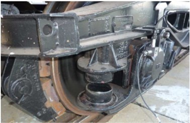
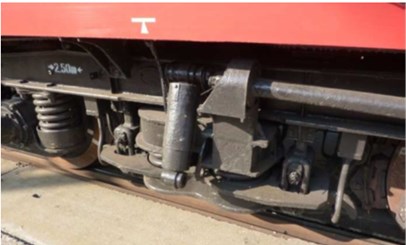
The suspension damages, the same as in the case of simulation study, were implemented in the wagons during experimental test of the monitoring system prototype: stiffness reduction in the goods wagon with Y25 bogies and damping reduction the passenger wagon. Stiffness reduction of primary suspension was achieved by removing one packet of coaxial springs on the left side of the wheelset bearing, at one wheel only (Fig. 9(a)). In the case of passenger wagon, one secondary damper was disconnected (Fig. 9(b)).
Fig. 9a) Goods wagon bogie with removed springs on one side and b) passenger car running gear with secondary suspension damper disconnected
a)
b)
Data was recorded by means of piezoelectric accelerometers. Acceleration signals were sampled at 1500 Hz on a distance of 500 m with constant speed (with permissible deviations of +/− 5 km/h). Then data was processed and sent to the system’s server. The basic parameters of the accelerometers are presented in Table 6.
Before computing diagnostic parameters, acceleration signals are filtered with use of the following filters [22]:
– lowpass filter 10 Hz, – bogie frame, lateral direction,
– lowpass filter 20 Hz, – bogie frame, vertical direction,
– bandpass 0.4-10 Hz, – body, both directions.
Since the monitoring system unit has to deal with a large amount of data and send it via GSM which has limited data transfer, only filtering and statistical analysis – calculation of statistical parameters is possible for sufficiently fast operation of the entire monitoring system including operator’s server and software.
The experimental track layout is depicted in Fig. 10. Total track length is 7725 km.
Table 6The basic parameters of the accelerometers
Parameter | Accelerometer | |
VIS-311A (on bogie) | VIS-311B (on body) | |
Sensitivity | 100 mV/g | |
Measuring range | +/– 50 g | |
Frequency range | 0.5 – 10 000 Hz | 0.2 – 15 000 Hz |
Resolution | 350 μg | 50 μg |
Resonance frequency | 25 kHz | 30 kHz |
Fig. 10Layout of the experimental track in Żmirgród
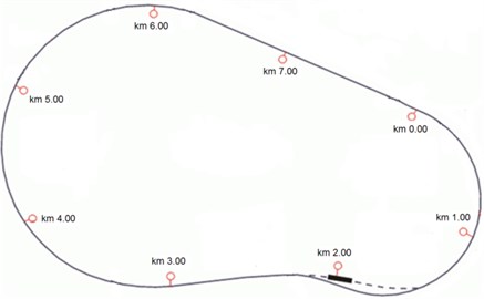
The analysis was performed on data recorded on the following track sections of consciously welded track supported on concrete ballasts:
– tangent section, between 6th and 7th kilometer;
– curved section 900 m, between 5th and 6th kilometer.
The off-line analysis of the measuring signals should be performed obligatory for the monitoring system calibration purpose, for each new type of vehicle it is installed on. In the following research it was necessary to set the limit values for the goods and passenger wagons, as well as different conditions such as speed and track sections of different geometry.
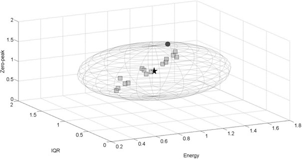
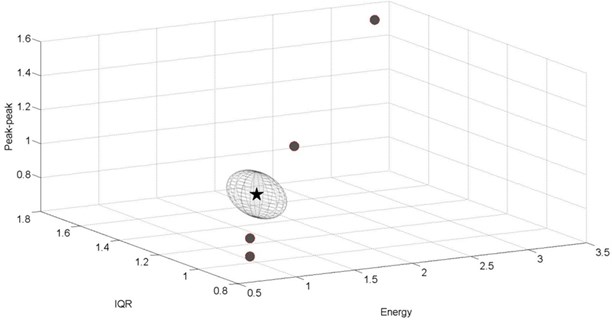
Below, the results of the third-level analysis are presented in the form of 3D plots. The reference point is illustrated as a star of coordinates (1, 1, 1). The permissible space of radius is represented as a sphere − in fact due to different axis maximal values it takes shape of an ellipsoid. The dot and square markers refer to the taken measurements on the same track sections of length of 500 m. If marker (point) is located inside the permissible space − it is a square and indicates that no suspension damage was detected. If damage was detected, then the marker is a dot. The number of points (markers) is not equal for all the cases, due to different number of passages for various conditions.
Track quality indicator values on the test track sections (tangent and curved) varied from 1.2 up to 1.5 depending on the measurement. According to the proposed track classification [26] its quality can be found as good. This track conditions are not expected to “mask” the suspension damages reflected in the vibration signals due to low magnitude of the excitations.
5.1. Spring damage detection
The analysis of the results of stiffness reduction in the goods wagon passing at 80 km/h on a curved track section ( 900 m) are depicted in Fig. 11-12. Damage detection for the following case is much more efficient when analyzing acceleration signals recorded in lateral direction. Eleven amongst sixteen obtained points are located beyond permissible space (Fig. 11). For signals recorded in vertical direction, only one point indicates the damage (Fig. 12).
Fig. 11Experimental results for the damaged goods wagon, v= 80 km/h, lateral direction, curved track section R= 900m, F= 0.196
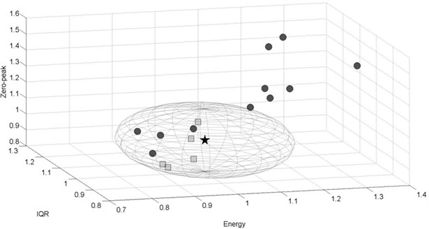

Fig. 12Experimental results for the damaged goods wagon, v= 80 km/h, vertical direction, curved track section R= 900m, F= 0.637

5.2. Damper damage detection
The results of secondary suspension damage – damping reduction in the passenger wagon are presented in Fig. 13-14. During the passage at 60 km/h on the same curved track section (Fig. 13) as in the case of goods wagon, fault detection was possible basing on the analysis of two among four recorded measurements in lateral direction.
In the case of higher speed 120 km/h on a tangent track (Fig. 14), successful damage detection was possible due to analyzing all of four measurements. The obtained points are located in a substantial distance from the permissible space.
In the case of the real wagons, the adopted damage detection method showed that both types of damage can be reflected in lower coordinates values (< 1) as well as higher coordinates values (> 1) than for the reference point. The experimental tests indicated that acceleration signals recorded in lateral direction also provide diagnostic information, what was not apparent in the case of simulation results. For diagnostic purpose, it is important to analyze signals recorded in both directions.
It should be noted that vibration of the main parts of the vehicle: wheelsets, bogies and body have stochastic nature. In some cases, the faults were not frequently detected despite passing the same track section at the same speed. However, for other cases fault detection was successful for each taken measurement. It is important to make decision on the alerts in the system basing on several samples to reduce risk of false alarms or omitting occurred damages. One can set the threshold for generating alerts in the monitoring system basing on several measurements (samples), e.g. if the distance between points in diagnostic space is exceeded for two out of three measurements.
Fig. 13Experimental results for the damaged passenger car, v= 60 km/h, lateral direction, curved track section R= 900 m, F= 0.598
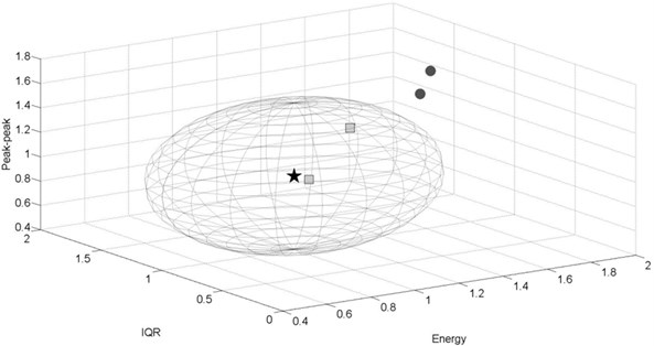

Fig. 14Experimental results for the damaged passenger car, v= 120 km/h, vertical direction, tangent track section, F= 0.133

6. Conclusions
The demand on providing regular and safe rail transport services induces development of the monitoring systems whose operation covers the rail vehicle’s subsystems which have not been an aim of the monitoring recently. The rail vehicle suspension is a complex system which is directly responsible for safety. Condition assessment of this subsystem is very difficult due to strong correlation of its dynamic responses and excitations which can “mask” the occurred damages. The developed monitoring system within the framework of the project ‘MONIT − Monitoring of Technical State of Construction and Evaluation of its Lifespan’ is able to deal sufficiently with those difficulties using a simple, model-less approach.
In order to estimate excitations and facilitate suspension condition assessment (fault detection) the algorithm for track quality indicator is implemented (the first level). Detection of suspension damages is performed on two levels − the second level is the assessment of statistical parameters compliance with normative values. The third level is the analysis of the selected statistical parameters in a three-dimensional diagnostic space. The advantage of the implemented method is ability of detecting faults of various impact on diagnostic signals’ amplitude (decrease or increase). This is possible since symptom of suspension damage is an exceedance of distance between specific points in the diagnostic space. The method proved its diagnostic usefulness in off-line analysis of experimental data.
References
-
http://www.skf.com/binary/68-62755/RTB-1-08-Bogie-CoMo.pdf.
-
Fan H., Wei X., Jia L., Qin Y. Fault detection of railway vehicle suspension systems. Proceedings of the 5th International Conference on Computer Science and Education (ICCSE), Hefei, Anhui, China, 2010, p. 1264-1269.
-
Goda K., Goodall R. Fault-detection-and-isolation system for a railway vehicle bogie. Vehicle System Dynamics Supplement, Vol. 41, 2004, p. 468-476.
-
Li P., Goodall R. Model-Based Condition Monitoring for Railway Vehicle Systems. University of Bath, UK, 2004.
-
Jesussek M., Ellermann K. Fault detection and isolation for a full-scale railway vehicle suspension with multiple Kalman filters. Vehicle System Dynamics, Vol. 52, Issue 12, 2014, p. 1695-1715.
-
Wei X., Liu H., Qin Y. Fault diagnosis of rail vehicle suspension systems by using GLRT. Chinese Control and Decision Conference (CCDC), Mianyang, China, 2011, p. 1932-1936.
-
Liu X. Y., Alfi S., Bruni S. An efficient recursive least square-based condition monitoring approach for a rail vehicle suspension system. Vehicle System Dynamics, Vol. 54, Issue 6, 2016, p. 814-830.
-
Wei X., Jia L., Guo K., Wu S. On fault isolation for rail vehicle suspension systems. Vehicle System Dynamics, Vol. 52, Issue 6, 2014, p. 847-873.
-
Wu Y., Jiang B., Lu N., Zhou D. ToMFIR-based incipient fault detection and estimation for high-speed rail vehicle suspension system. Journal of the Franklin Institute, Vol. 352, Issue 4, 2015, p. 1672-1692.
-
Xue P., Chai X., Zheng S. Research on vehicle diagnosis based on state-space method. Artificial Intelligence Research, Vol. 4, Issue 2, 2015, p. 55-60.
-
Gu X., Mao Z., Jiang B., Zhan Y. Multiple-model based fault diagnosis for actuators of rail vehicle suspension. 27th Chinese Control and Decision Conference (CCDC), 2015, p. 1676-1681.
-
Tsunashima H., Hayashi Y., Mori H., Marumo Y. Condition monitoring and fault detection of railway vehicle suspension using multiple-model approach. Proceedings of the 17th World Congress the International Federation of Automatic Control, Seoul, Korea, 2008, p. 8299-8304.
-
Tsunashima H., Mori H. Condition monitoring of railway vehicle suspension using adaptive multiple model approach. International Conference on Control Automation and Systems (ICCAS), Gyeonggi-do, Korea, 2010, p. 584-589.
-
Wei X., Jia L., Liu H. Data-driven fault detection of vertical rail vehicle suspension systems. UKACC International Conference on Control 2012, Cardiff, UK, 2012, p. 589-594.
-
Kojima T., Sugahara Y. Fault detection of vertical dampers of railway vehicle based on phase difference of vibrations. Quarterly Report of Railway Technical Research Institute, Vol. 54, Issue 3, 2013, p. 139-144.
-
Mei T. X., Ding X. J. A model-less technique for the fault detection of rail vehicle suspensions. Vehicle System Dynamics, Vol. 46, 2008, p. 277-287.
-
Mei T. X., Ding X. J. Condition monitoring of rail vehicle suspensions based on changes in system dynamic interactions. Vehicle System Dynamics, Vol. 47, Issue 9, 2009, p. 1167-1181.
-
Wei X., Guo Y., Jia L. MBPLS-based rail vehicle suspension system fault detection. 26th Chinese Control and Decision Conference (CCDC), 2014, p. 3602-3607.
-
Sakellariou J. S., Petsounis K. A., Fassois S. D. Vibration based fault diagnosis for railway vehicle suspensions via a functional model based method: a feasibility study. Journal of Mechanical Science and Technology Vol. 29, Issue 2, 2015, p. 471-484.
-
Gardulski J. Assessing the reliability of testing methods used for fluid telescopic shock absorbers in cars. Journal of Kones Powertrain and Transport, Vol. 15, Issue 1, 2008, p. 79-85.
-
Railway Applications. Testing for the Acceptance of Running Characteristics of Railway Vehicles. Testing of Running Behavior and Stationary Tests. EN 14363, 2007.
-
Testing and Approval of Railway Vehicles from the Point of View of Their Dynamic Behavior – Safety – Track Fatigue – Ride Quality. UIC 518, 2009.
-
Grzyb A. Application of measurement results of acceleration on wheelset bearing housing for track evaluation. Simulation in Research and Development, Vol. 3, Issue 2, 2012, p. 79-87.
-
Konop J., Konowrocki R. On evaluation of the wheelsets-track interaction quality in railway engineering. Machine Dynamics Research, Vol. 37, Issue 4, 2013, p. 61-70.
-
Garg V. K., Dukkipati R. V. Dynamics of Railway Vehicle Systems. Academic Press Canada, 1984.
-
Kostrzewski M., Chudzikiewicz A. Rail-track quality indicator towards rail vehicle driving dynamics. Proceedings of 14th MINI Conference on Vehicle System Dynamics, Identification and Anomalies, Budapest, Hungary, 2015, p. 211-218.
-
Melnik M., Sowiński B. The selection procedure of diagnostic indicator of suspension fault modes for the rail vehicles monitoring system. The e-Journal of Nondestructive Testing, Vol. 20, Issue 2, 2015, p. 159-166.
-
Melnik R., Sowiński B. Statistical Parameters of Acceleration Signals in the Process of Rail Vehicle Suspension Fault Detection. Selected Dynamical Problems in Mechanical Systems Theory and Applications in Transport, Oficyna Wydawnicza Politechniki Warszawskiej, Warsaw, 2014, p. 43-54.
-
Chudzikiewicz A., Melnik R. Statistical analysis of vibration for the rail vehicle suspension monitoring system. Proceedings of the 13th Mini Conference on Vehicle System Dynamics, Identification and Anomalies, Budapest University of Technology and Economics, Hungary, 2012, p. 149-155.
-
Melnik R., Kostrzewski M. Rail vehicle’s suspension monitoring system – analysis of results obtained from tests of the prototype. Key Engineering Materials, Vol. 518, 2012, p. 281-288.
-
Dizo J., Harusinec J., Blaticky M. Multibody system of a rail vehicle bogie with flexible body. Manufacturing Technology, Vol. 15, Issue 5, 2015, p. 788-795.
-
Kalker J. J. A fast algorithm for the simplified theory of rolling contact. Vehicle System Dynamics, Vol. 11, 1982, p. 1-13.
Cited by
About this article
The Authors express their gratitude for the financial support by the Polish Ministry of Science and Higher Education for the support of research within the framework of the Project Monitoring of Technical State of Construction and Evaluation of Its Lifespan – Monit. Action Operational Programme Innovative Economy.
