Abstract
In this article the dynamics and positioning accuracy of “MOTOMAN SSF2000” robotic system which is operating in heavy loaded high speed conditions was researched. To explore the dynamics of “MOTOMAN SFF2000” was used mobile processing equipment of „Brüel & Kjær”. Mechanical vibrations were tested at two different locations of the robot. One of the accelerometers was placed on the robot's base and the other one was placed on the robot's hand. Accelerometers registered the vibrations in three different axes with three different weigths. The mechanical vibrations and positioning accuracy were explored moving robot‘s hand in a linear direction.
1. Introduction
The rapid developments in technology, increasing demand for accurate robots. For more than 30 years, yet never felt such a strong recovery in robots industry. During the first three quarters of 2010, robots sales increased twice compared to the same period in 2009. The rapid growth in demand for robots in North America reflects the role of robotics to improve productivity across industries, as well as soft-goods sectors, and there is increasing demand of robots for service market [1].
Modern industrial robots are true engineering marvels. Human-sized robot can easily lift loads weighing a hundred kilos, and move it very quickly with only ±0,147 mm error. In addition, these robots can work 24 hours a day, all year round without any trouble. Although they are reprogrammable and can perform many different operations, but usually they are programmed once (especially in the automotive industry) to carry out one stable operation [2].
While modern industrial robots today demonstrates a very high accuracy, still there are factors that can affect the accuracy of the robot [3]. One such factor is the mechanical vibrations. Ever since human began to produce robots for industrial use, and especially when the need of extra power occurred robots got motors. After that, vibration reduction problem consolidated engineers. Over the past 15-20 years it was created new technology to measure vibrations, which is designed to explore the modern equipment working with high loads and speeds. The measurement and analysis process is intelligently carried out with universal electronic equipment using piezoelectric accelerometers, which converts vibrations into an electrical signal [4, 5, 6].
Robot’s positioning accuracy also depends on the environment in which research was performed: from external vibrations and temperature change [7].
The aim of this article is to explore robotic system mechanical vibrations and positioning accuracy under different loads and speeds, using “Bruel & Kjaer” vibration measurement equipment and simple indicators. To eliminate external interference robotic system is installed on vibro-isolating support [8, 9].
2. The object and methodology of the research
Object of the research is robot “Motoman SSF2000” with especially for it designed storage system and base. “MOTOMAN SSF2000” maximal live load is 6 kg. It is designed to avoid collisions, and can save 15 % of the work time. SSF2000 model is one of the most productive industrial robots [10].
During technological process, robot gripper must occupy certain position in the space, which is prescribed by software as values of generalized coordinates of robot links. During robot operation it happens, that generalized coordinates of robot has errors to real position of robot links. Due to this occurs cinematic error of robot links, which is estimated positioning error. This error can be expressed as linear or angular.
Linear cinematic error of gripper can be evaluated according:
where – generalized coordinates error of th link.
Angular error of manipulator is called angle, which is necessary to apply to gripper to achieve that axes of coordinate system would be parallel to axes of coordinate system .
Each link of the robot has an automatic drive unit, which provides a certain positioning accuracy. Accuracy of the moving link can be evaluated as follows:
While in whole positioning process is consisted of linear and angular movement, overall robot positioning error would be expressed as:
where – linear movement link error, – angular movement link error.
Allowed robot positioning error is assumed to be:
where – allowed base error, defined by manipulated object placing position requirements [11].
3. Experimental research
The aim of this article is to investigate mechanical vibrations and positioning accuracy of mentioned robot when it operates at 50 mm/s speed working with three different weights: 2 kg, 4 kg and 6 kg.
During the investigation of positioning accuracy, indicators were set out in such a way that displacement of all three (, and ) of the coordinate axes can be measured. Rectangular calibrator was seated to the gripper of the robot.
During the study three indicators respectively contact with three walls of the calibrator (Fig. 1).
Fig. 1Stand with calibrator and indicators
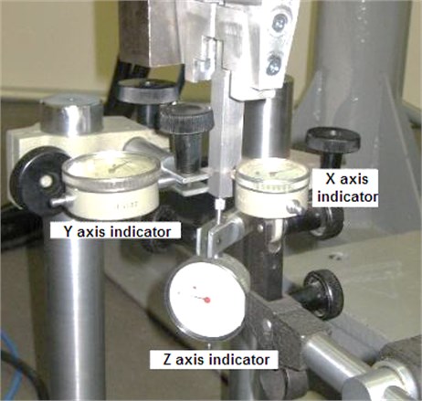
Before the experiment, robots hand is placed in a position which lets to capture the current location of it (Fig. 1). At that time, the indicator readings are set to the zero point. Then the job is determined to the robot, after which it must again return to the same position from which the work began. When it returns and becomes steady, indicator readings are recorded. Before the next experiment, indicator readings are set to zero point again.
Fig. 2Robot’s positioning accuracy dependence from load when movement speed is 50 mm/s
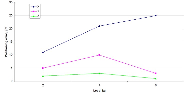
Positioning accuracy experiments were performed with constant 50 mm/s speed and three different loads: 2 kg, 4 kg and 6 kg. Results are shown in Table 1.
Table 1Positioning accuracy experiment results when robot’s movement speed is 50 mm/s
Load, kg | Average deviation, µm | ||
axis | axis | axis | |
2 | 11 | 5 | 2 |
4 | 21 | 10 | 3 |
6 | 25 | 3 | 1 |
The following chart (Fig. 2) shows the average results of the experiment. It was carried out on 150 tries.
Research shows that robot’s positioning accuracy depends of the load. Increasing load leads to positioning error increment. While load which increases with increasing weight and positioning errors for robot is less accurate in axis.
Next step is vibration activity investigation with the same movement speed of 50 mm/s.
Fig. 3Investigation of mechanical vibrations: 1 – attached weight, 2 – accelerometers, 3 – robot
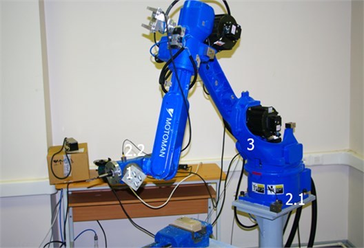
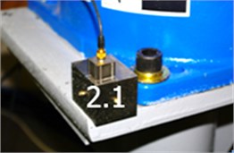
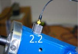
In Figure 3 we can see that robot’s (3) mechanical vibrations were analyzed with three different weights (1). Accelerometers were attached so that the first (2.1) measured vibration on the robots base and the second (2.2) was attached so that the vibrations measured on the rear of the robots hand, close to attached weight. Both accelerometers (2) measured mechanical vibrations on , and axes. Robots (3) hand was programmed to move 200 mm distance on Y axis. The results of accelerometers (2) are transmitted to the movable mechanical vibrations measurement equipment “Bruel & Kjaer”. Later the results are monitored and processed with the computer.
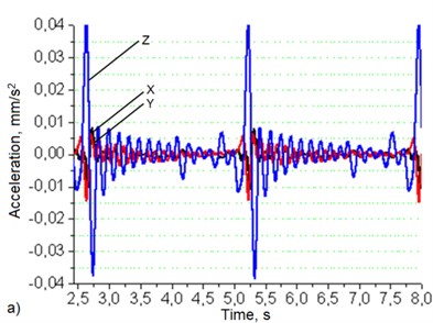
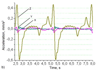
Fig. 4Robotic system’s base (a) and manipulator’s hand (b) oscillation graphs when robot's movement speed – 50 mm/s, load – 2 kg
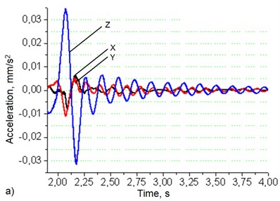
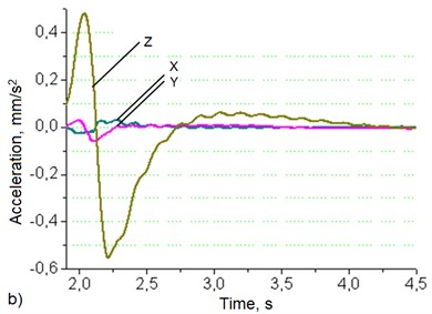
Data in Fig. 4(a) shows that at the load of 2 kg robotic system’s base vibrations level in the direction is about 4 times higher than in the and directions. Manipulator’s hand Fig. 5(b) vibrations level in the Z direction is 17 times higher than in the direction and 10.4 times higher than in the direction.
Robot’s vibrations when it operates at 50 mm/s with 4 kg of load are shown in Fig. 5.
Data in Fig. 5(a) shows that at the load of 4 kg robotic system’s base vibrations level in the direction is about 4 times higher than in the and directions. Manipulator’s hand Fig. 5(b) vibrations level in the direction is 15.7 times higher than in the direction and 9.4 times higher than in the direction.
Robot’s vibrations when it operates at 50 mm/s with 6 kg of load are shown in Fig. 6.
Fig. 5Robotic system’s base (a) and manipulator’s hand (b) oscillation graphs when robot's movement speed – 50 mm/s, load – 4 kg
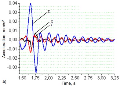
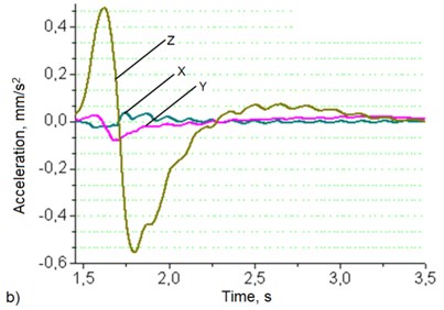
Fig. 6Robotic system’s base (a) and manipulator’s hand (b) oscillation graphs when robot's movement speed – 50 mm/s, load – 6 kg
Data in Fig. 7(a) shows that at the load of 6 kg robotic system’s base vibrations level in the direction is about 3.7 times higher than in the and directions. Manipulator’s hand Fig. 7(b) vibrations level in the direction is 14.3 times higher than in the direction and 9.4 times higher than in the direction.
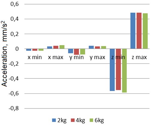
Robotic system’s base (a) and manipulator’s hand (b) oscillation statistical parameters (min and max value) charts which show the vibration dependence from varying load are presented in Fig. 7 and Fig. 8.
Chart very clearly shows that the robot’s base vibration level depends on the increasing weight of the load.
In manipulator’s hand data chart we can see that the difference between the vibrations highest and the lowest values are not significant and do not exceed 8 %. It can also be seen that the data in a chart showing the vibration’s highest and the lowest values are not as strongly dependent on the increasing weight of the load.
Fig. 7Robotic system’s base oscillation statistical parameters (min and max value) chart. Manipulator’s movement speed: 50 mm/s, load: 2 kg, 4 kg, 6 kg
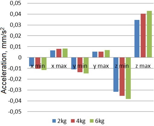
Fig. 8Manipulator’s hand oscillation statistical parameters (min and max value) chart. Manipulator’s movement speed: 50 mm/s, load: 2 kg, 4 kg, 6 kg
4. Conclusion
1. During vibration activity and positioning accuracy research there were investigated robot’s vibrations and measured displacement in all three coordinate axes (, , ) and it was determined that the robot working at high speeds and high loads the highest vibrations are encountered in the coordinate axis while the highest inaccuracy is encountered in the coordinate axis.
2. Vibration activity research in which robot’s “MOTOMAN SSF2000” produced vibrations were examined in two different parts showed that the robot's hand resulting vibrations are much higher than the vibrations arising from the robot's base: in the coordinate axis about 2.5–5 times higher, in the axis about 5–7 times and in the axis about 11–16 times.
References
-
International Robot Federation. 2011, http://www.ifr.org/
-
Industrial Robots. 2011, www.learnaboutrobots.com/
-
Yan Jin, I-Ming Chen, Guilin Yang Kinematic design of a family of 6-DOF partially decoupled parallel manipulators. Mechanism and Machine Theory, 2009, p. 1-11.
-
Bruel & Kjaer, Measurement of Vibrations, 2010, http://www.bksv.com/
-
Vekteris V., Mokšin V. The modular principle of design of adaptive film lubrication bearings. Mechanika, Vol. 4(84), 2010, p. 53-57.
-
Augustaitis V., Bučinskas V., Pauža V. Application of frequency method for defining threaded joint tightening degree. Solid State Phenomena, Mechatronic Systems and Materials, Collection of Papers from the 1st International Conference (MSM 2005), Vilnius, Lithuania, Vol. 113, 2006, p. 277-280.
-
Koseki Y., Tanikawa T., Chinzei K. MRI-compatible micromanipulator: positioning repeatability tests and kinematic calibration. 31st Annual International Conference of the IEEE EMBS, 2009, p. 1-4.
-
Kilikevičius A., Jurevičius M., Berba M. Research of dynamics of a vibration isolation platform. Journal of Vibroengineering, Vol. 12, Issue 3, 2010, p. 361-367.
-
Kilikevičius A., Jurevičius M., Vekteris V., Maskeliūnas R., Stankūnas J., Rybokas M., Petroškevičius P. Research of positioning accuracy of robot Motoman SSF200. Journal of Vibroengineering, Vol. 12, Issue 4, 2010, p. 664-668.
-
Motoman. 2011, www.motoman.com
-
Bakšys B. Robot Technique. Technologija, 2004, p. 40-81, (in Lithuanian).
About this article

