Abstract
Micro aerial vehicles design represents a challenge that lasted for years and the fact that they operate in a low Reynolds range, which makes the unsteady aerodynamic effect more influential, made the direct computational fluid dynamics simulation expensive in time and money, and an alternative method especially in the early phase of the design would be very beneficial and rentable. In this work the flight a flapping wings operated micro aerial vehicle was investigated by the simulation of the mechanical equations of motion in order to have an approximation of the true motion behavior and the flying condition of the vehicle, in the same time this approach present a model that can be electronically implemented to make the MAV auto-controlled by imposing some criteria. The equations were developed in spherical coordinates system, and simulated using the software Mathcad, and some of the constant related to the size of the vehicle are variated to match different range of existing flying animals from insects to birds, a concept of two different drag coefficient for the upstroke and down stroke was used successfully to model the flapping wing. And giving the fact that lots of parameter were simplified or neglected which lessen the accuracy, it gave good approximation, and the model can be used for auto-control by predefined flying path. Beside the main simulation work a small experimentation on a model wing covered in feather was conducted in a subsonic wind tunnel in order to present a practical alternative that economize energy by reducing the drag in upstroke, and it was found that the direction of the feather plays a significant role in the drag reduction and we concluded that the use of such materials can greatly improve the performances, and economize the energy used to operate such vehicles.
1. Introduction
Despite the great advance in in fixed wing vehicles, flapping wings vehicles still have lots of secrets for engineers, though unsuccessful in many cases and very hard to apply for a man carrying transportation, fixed wings took a major place in the aeronautics field due to its simplicity, durability, efficiency, and safety at the large scale required to carry humans.
However in the recent years much more researches are conducted on the small scale flapping wings, and this because of the need to a much smaller and more maneuverable aerial vehicle, that’s indeed needed in many combat or reconnaissance situations especially that more and more operation are conducted in urban environment, which require a real time surveillance inside closed or narrow area , something that available unmanned aerial vehicle (UAV) does not provide, which increased the need for MAVs (micro aerial vehicles) and NAVs (Nano aerial vehicles) those vehicles are efficient, agile, and can carry a camera and other sensing equipment.
Research and design of such vehicle was encouraged by several organizations like DARPA (Defense Advanced Research Projects Agency) [1], that initiate the MAVs project which aimed to solve the technical barrier that prevent from the realizations of such machine.
2. Definition of MAV
They are affordable, fully functional, militarily capable, small flight vehicles in a class of their own. The definition employed in DARPA’s program limits these craft to a size less than 15 cm (about 6 inches) in length, width or height. In addition, gross takeoff weight of no more than 100 g.
This physical size puts this class of vehicle at least an order of magnitude smaller than any missionized UAV developed to date.
Four types of configurations [2] exist in this category: fixed-wing, rotary-wing, and flapping wings, the fourth class is without propulsion and is called passive.
Last years experienced some advance in the MAV field and there was several promising flapping wing operated vehicle, like the one Festo Company revealed in March 2011, the SmartBird an autonomous ultra-light unmanned aerial vehicle with a focus on a better aerodynamics and a high maneuverability [5], and BionicOpter, a dragonfly-like AV a little bit bigger to be called MAV due to its 63 cm wing span and 44 cm long, it has an ultra-light weight of 175 g, and probably the most amazing thing about it is its 13 degree of freedom.
3. Statement of work
A motion study of a flapping wing operated micro aerial vehicle was performed by simulating the classic motion’s equations of mechanics by variating each time one of the variables approached value for the drag coefficient of birds and insects were used, all performed in a spherical coordinates system, and this by using the Mathcad software.
Using the same equations, a control system can be implemented electronically to steer the MAV.
Along the numerical investigation, some experimental works was conducted in the wind tunnel facility provided by Riga technical University, which consisted of testing a wing’s drag coefficient and its variation between the upstroke and the down stroke.
4. Numerical investigation with Mathcad
4.1. Theoretical investigation
The classical mechanic theory describes well the flight of the vehicle, the equations of motion (or equilibrium) which results from Newton’s second law describe the flapping wings vehicle, and other systems of coordinates than the rectangular were used, because it is best suited for this particular motion in space.
Newton’s 2nd law stipulates that the resultant of all the forces acting on a particle is proportional to the acceleration of the particle:
By applying this basic principal to a body in motion in a plan the equations in a rectangular basis would be:
Fig. 1Spherical coordinates
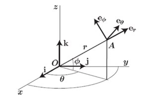
In spherical coordinates, two angles were used in addition to a distance to specify the position of a particle, radar localization is show in Fig. 1.
The acceleration is:
Therefore the equations of motion in 3D spherical coordinates is:
The equations of motion as seen before and despite their simplicity can be used to simulate the flight of a flapping wing vehicle; we used Mathcad after writing the equations in a syntax where we can use the increment in time in order to simulate in a certain degree of accuracy the flight.
The original idea of this work is the consideration of the lift force more or less equal to the drag force but, as we observe from nature, when a wing is in the upstroke the animal uses its muscle to change the shape of the wing so it will have less drag therefore a smaller drag coefficient in contrast in the down stroke the shape of the wing is optimal so for the biggest lift force which is the opposite of the drag force if we change the direction of the axis, therefore a biggest drag coefficient .
To find the 3D equation a projection of all the expressions on their respective axis.
A study case of each coordinate axis gave the following accelerations equations:
For the radial, coordinate axis:
For the polar axis:
The azimuth coordinate axis:
5. Mathcad manipulations
After writing all the equation in Mathcad with the proper syntax, the specifications set by DARPA which are: 100 g.
Several manipulation were performed on different parameters and as we see on Figs. 2, 3, the damping coefficient plays a major role in the stabilization of the flight path.
Fig. 2Vertical coordinates in the spherical case
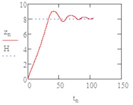
Fig. 3The flight path in (x, z) plan b1= 0.05
More manipulations were performed on different parameters [7] the results are illustrated in Figs. 4-6.
Fig. 4The vertical coordinates b1= 0.1
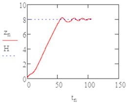
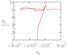
Fig. 5The flight path in (x, z) plan b1= 0.1
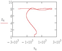
Fig. 6The flight path in (x, y) plan as helicoid
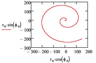
From the Figs. 4-6 it was obvious the instability occurred in the axis so we changed the damping coefficient by and we varied separately.
By increasing of the damping coefficient (0.1 and 0.15) we had nearly similar results but far more stable, as it’s illustrated in the last graphs where we can see the path of flight in the (, ): with a damping coefficient of 0.1 the MAV reach the limit height smoothly and continue to perform the flight in a circular path.
6. Experimental work
The experimental work consisted simply of measuring the drag force that is produced by an artificial pair of wings covered with feather (Fig. 7) from both sides, and we tried to see if the bend of the profile as well as the feather orientation affected the drag.
Fig. 7The tested artificial wing
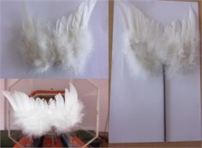
Fig. 8Graph that illustrates the result of the measurements performed on the wing
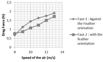
Results are illustrated in Fig. 8.
It was obvious that there is a difference between the two cases, in the first case where the air flow was against the orientation of the feathers and the curve was against the flow the drag force was higher, but for the second case we can see that the force was generally less than the first case, such difference can be used in flapping wing vehicle in order to design a lighter and more efficient wings.
7. Results and conclusions
We can summarize the results in the next points:
1) One of the major parameter that influences the MAV flying is the damping coefficients, which have great effect on the stability of the MAV especially.
2) It is possible to use some formulas found in the literature that link the flapping frequency with a group of other parameter.
3) The flapping frequencies have to be defined and limited under certain value to keep up with the reality, and the available mechanism for flapping.
4) The difference between the 2 drag coefficients plays a central role in making the MAV fly just like the amplitude.
References
-
Petricca L., Ohlckers P., Grinde C. Micro- and Nano-air vehicles: state of the art. International Journal of Aerospace Engineering, Vol. 2011, Issue 1, 2011.
-
Al-Bahi, I. M. A.-Q. A. A. M. Micro aerial vehicles design challenges: state of the art review. Proceedings of the SAS UAV Scientific Meeting and Exhibition, Jeddah, Saudi Arabia, 2006
-
James M., McMichael C. M. S. F. Micro air vehicles – toward a new dimension in flight, 1997.
-
Mueller T. J. Aerodynamic measurements at low Reynolds numbers for fixed wing micro air vehicles. Tech. Rep., University of Notre Dame, Notre Dame, The Netherlands, 2000.
-
Companu Festo, http://www.festo.com/cms/en_corp/13165.htm.
-
Pennycuick C. J. Wing beat frequency of birds in steady cruising flight: new data and improved predictions. The Journal of Experimental Biology, Vol. 199, 1996, p. 1613-1618.
-
Abdessemed A. C. Investigation of the flight of a micro aerial vehicle. Master thesis, Riga Technical University, 2013.
About this article

