Abstract
The paper addresses the possibilities of applying the cam-gate system to product quality control. Particular attention is paid to the concept of the test stand simulating the operation of the product quality control automatic machine with the use of the CCD camera. Dimensional parameters of rollers were measured by means of a micrometer screw and the CCD camera at the simulation stand in the cam-gate system and the results of measurements were compared. The paper presents the cost system structure of an enterprises and factors affecting the selection of inspecting-sorting automatic machines in the aspect of the prescribed quality parameters which condition the optimal selection. The article addresses the application of the FMEA method in the process of selection of inspecting-sorting devices.
1. Introduction
The knowledge about the application of a product quality control station when operations are robotized is limited. It is related to technical problems which occur at the stage of implementation of control systems in serial and mass production. Large industrial concerns are not willing to reveal the technical details of quality control organization, so as not to provide competitors with useful tips in the struggle for a customer. The solutions, which are known and have been published, are typical and as a rule just being phased out from technological lines [1, 3].
Numerous examples of the application of various inspecting and inspecting-sorting devices, which objectively control quality parameters, can be found after a careful analysis of the most recent publications this paper, however, focuses only on the inspecting-sorting devices used in mass production [2].
The application of a system to a production line depends to a great extent on factors determined by economic possibilities as well as technical conditions which must be satisfied for the smooth operation of the control process. In the case of modern control systems, a complete analysis of the process subject to quality control is required. The data collected, after being statistically elaborated and verified in accordance with the quality assumptions, provide information about the quality of the process and reasons for defects which arose in the process [3, 4].
2. Project of simulation stand arrangement – conceptual assumptions
In order to check the cam-gate system in product quality control in practice (small-sized rollers) a test stand simulating the partial operation of the inspecting-sorting automatic machine was designed. The operation of the stand was limited to practical simulation of operation of the measuring module cooperating with the control and transporting system [6].
The fundamental assumption was to compare the results of quality parameters measurements taken during operation of the inspecting – sorting device with the results obtained during measurements taken in laboratory conditions with the use of a micrometer screw.
Performance of the following tasks was included in the project [5, 6]:
– Providing the roller to the control zone,
– Measurement of quality parameters (cam-gate system),
– Classification into sorting groups (cam-gate system),
– Transferring the roller from the control zone to a position that facilitates putting the detail into the sorting device.
The above mentioned tasks were carried out in an automatic cycle.
Fig. 1 illustrates the arrangement of the simulation module of the inspecting-sorting device under consideration.
The principle of operation of the module is as follows: the roller under control (2) fixed in V-blocks (3) is transferred by means of a linear servo-motor (7) to the control zone. Upon taking measurements with the CCD camera (4) using the source of light (1), the detail was classified and passed through to the sorting device after a previous shift to the initial position. The source of light (1) together with the CCD camera (4) were located coaxially in the body frame (6) [7, 9].
Fig. 1Scheme of the arrangement of the simulation module
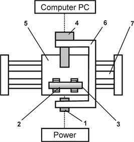
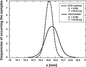
Fig. 2The results of experiment for CCD camera (dashed line) and micrometer (solid line)
3. Analysis of the possibilities of applying the cam-gate system
A series of check measurements was performed in order to analyze the possibility of applying the cam-gate system in the measuring module of the inspecting-sorting automatic machine.
The measurements included checking the dimensions of sample diameters (rollers 10.50.1 [mm], in the amount of 30 pieces) by means of the cam-gate control system mounted on the simulation stand.
4. Advantages and disadvantages of the modules employed in inspecting-sorting automatic machines
In order to perform FMEA, the basic failure modes following from the technique of making measurements and constructional solutions of the inspecting-sorting device were described. Depending on the technique of measurement, efficiency and the material of which the element being inspected is made, inspecting-sorting automatic machines may have various typical constructional solutions [8].
The structure of characteristic modules described in affects the final result of measurements and operational properties of the in inspecting-sorting device.
A thorough analysis makes it possible to find a “weak” link in the structure and allows remedy actions not defining, however, how to perform them. While making a comparison, advantages and disadvantages of the systems employed in inspecting systems with the use of the CCD camera and other sensors (pneumatic ones) were specified.
In the linear method of product flow, products are transported on a conveyor belt, in front of which there are cameras and sources of light. The method used in the machine building industry and glass making industry is characterized by the following advantages: high speed of transport; good insight into the product being inspected; possibilities of product concentration.
Besides the advantages, the method has also got drawbacks which include: possible jamming of products; noticeable vibrations of the conveyor belt; slide of the transport system; safety hazards at large linear speeds; the device is large and occupies a lot of space.
Another method is the carousel method, which consists in placing products on the circumference of a circle, which while being moved in front of the inspecting stations are rotated at a constant speed along the axis of symmetry. The advantages of the method include: little space required; secure fixture of the product; defined sequence of products; accurately set position; relatively low vibrations of the mechanical system; favorable position of the element being inspected in the case of undesired gravity centre.
The disadvantages include: slow operation; small concentration of products; danger of scratching the base of products being inspected.
A CCD camera is not always necessary to perform the analysis and in some cases its use is even not possible. It follows from objective reasons, most frequently economic ones, and from the organization of quality control procedures in an enterprise. In the event of statistical quality control (where there is no need to check 100 % of products) inspecting all quality features in a continuous manner does not seem optimal [9].
The use of other sensors, e.g., pneumatic ones, for inspecting quality parameters can suffice, however it limits the capacity of inspection. In such a case there is no technical possibility of inspecting such defects as discolorations and insertions. The advantages offered by pneumatic sensors employed in the measuring system of an inspecting-sorting automatic machine include: simple structure; secure operation; spark safety; small sensitivity to vibrations of the external system; possibility of application in various conditions of the environment; relatively low cost.
The main disadvantages of pneumatic sensors employed in the measuring system of an inspecting-sorting automatic machine include: low speed of operation; relatively not too flexible application; no possibility of measuring inclusions and scratches of the surface; necessity of supplying air of strictly defined parameters to the system.
The use of a CCD camera in the measuring system of an inspecting-sorting automatic machine offers the following advantages: short time required for identification of quality parameters; large flexibility of the inspecting system; relatively large efficiency of inspection (up to 28 pieces per second); possibility of identifying inclusions and discolorations; high accuracy of measurement (up to do 0.001 [mm]); compatibility of the system with other units of the controlling and technological systems.
The method, however, has the following drawbacks: complicated structure of the measuring system (optics, mechanics, IT, automation); sensitivity of the system to external vibrations; sensitivity to changeable conditions of the environment (pollution, oil emulsions, reflections); relatively high cost (software and the CCD camera).
5. FMEA for selected modules
Table 1 and Table 3 illustrates FMEA for a module of the inspecting-sorting automatic machine, in which the CCD camera was used for measurements (Fig. 3). The potential failure mode (defect) of the system, i.e., incorrect readings of parameters, affects directly manufacturing of products which are defective in terms of quality. It follows from Table 3 that the following causes affect most significantly the readings of quality parameters:
– Incorrect description of technical conditions for making the measurements (duration of measurement, accuracy, lighting, efficiency),
– Delayed reaction of the measuring system to changes in the ambient temperature and in the temperature of the element being inspected,
– Faulty construction of the system connecting the optical elements and the source of light.
Table 2 illustrates FMEA for the module of the inspecting-sorting automatic machine, in which pneumatic sensors of MHAR type were employed for measurements (Fig. 4).
Fig. 3Measurement scheme – CCD camera
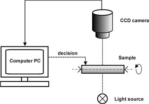
Fig. 4Measurement scheme – pneumatic sensor (Mahr)
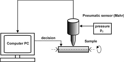
Table 1Ranking used in the FMEA method – research
Risk of occurrence | Significance | Detectability | Severity | ||||
Failure is unlikely | 1 | Insignificant | 1 | High | 1 | High | 125-1000 |
Very low | 2-3 | Unimportant | 2-3 | Moderate | 2-5 | Moderate | 1-125 |
Low | 4-6 | Moderate | 4-6 | Low | 6-8 | Low | 1 |
Moderate | 7-8 | High | 7-8 | Very low | 9 | ||
High | 9-10 | Very high | 9-10 | None | 10 | ||
Table 2FMEA
Product / process / system identifiers | ||||||||
Name/Designation of product/sys. | Potential failure mode | Potential effects of failure mode | Potential causes of failure modes | Current state | ||||
Method of control | Assessment | |||||||
Risk of occurrence | Significance | Detectability | Severity | |||||
AKS inspecting-measuring system – with the use of a CCD camera | Incorrect readings of quality parameters | Production of bad quality products | Maintaining wrong pressure in the supply system | Pressure measurement | 5 | 8 | 3 | 120 |
Untightness of the system due to fractures of couplings, tubes, washers | Pressure measurement | 6 | 9 | 5 | 270 | |||
Wear of mechanical elements intended to maintain the prescribed pressure (membranes, springs, surfaces of batteries) | Checking the elements of the structure | 6 | 8 | 5 | 240 | |||
Use of inappropriate pneumatic elements of large operational inertia (in the system – measurement – analysis – selection) | System inertia measurement | 3 | 6 | 3 | 54 | |||
Air content of incorrect parameters | Air content measurement | 5 | 8 | 3 | 120 | |||
Faulty setting of automatic pressure adjustment from the compressor to the system | Pressure measurement | 2 | 4 | 5 | 40 | |||
Faulty location of the product being inspected at the measuring stand | Analysis of the structure | 5 | 9 | 3 | 135 | |||
Large vibrations of the mechanical system due to faulty construction | Vibration measurement | 6 | 8 | 3 | 144 | |||
The causes of failure modes indicate that the following factors affect the correct readings of quality parameters:
– Untightness of the system due to fractured tubes or couplings,
– Wear of mechanical elements which keep the prescribed pressure (membranes, springs),
– Vibrations of the mechanical system due to a faulty construction of elements.
Table 3FMEA
Product / process / system identifiers | ||||||||
Name/Designation of product sys. | Potential failure mode | Potential effects of failure mode | Potential causes of failure modes | Current state | ||||
Method of control | Assessment | |||||||
Risk of occurrence | Significance | Detectability | Severity | |||||
AKS inspecting-measuring system – with the use of a CCD camera | Incorrect readings of quality parameters | Production of bad quality products | Incorrect calculation of optical system distances | Inspection measurement | 3 | 8 | 5 | 120 |
Incorrect selection of lenses | Measurement analysis of catalogue | 2 | 7 | 5 | 70 | |||
Incorrect construction of the system connecting optical elements and source of light | Camera and source of light axial symmetry measurement | 5 | 8 | 5 | 200 | |||
Inappropriate selection of optical sensors of insufficient number of pixels | Analysis of accuracy | 4 | 8 | 2 | 64 | |||
Faulty location of optical elements | Inspection measurement | 4 | 4 | 6 | 96 | |||
Faulty connection of elements of the measuring and optical systems sensitive to external factors | Operational measurement | 2 | 7 | 2 | 28 | |||
Incorrect location of elements relative to the measuring system | Analysis of location | 2 | 8 | 2 | 32 | |||
Incorrect feed of elements to the measuring system resulting in jamming | Operational measurement | 4 | 8 | 5 | 160 | |||
Incorrect feed of elements after they leave the measuring system resulting in jamming | Operational measurement | 4 | 8 | 5 | 160 | |||
Selection of programming language | Analysis of literature | 4 | 9 | 2 | 72 | |||
Incorrect description of model program describing shapes, dimensions and surface of elements | Analysis of program | 10 | 9 | 2 | 180 | |||
Incorrect description of process quality conditions relating to product classification and sorting | Analysis of program | 9 | 10 | 2 | 180 | |||
Faulty description of technical conditions in which measurements are made (duration of measurement, accuracy, type and intensity of lighting) | Analysis of program | 7 | 10 | 5 | 350 | |||
Delayed re action of the system to changes in illumination | Analysis of program | 8 | 9 | 2 | 144 | |||
Delayed reaction of the measuring system to changes in ambient temperature and temperature of the element being inspected | Analysis of program | 6 | 8 | 5 | 240 | |||
Inappropriate use of vibration damping elements | Experimental investigation | 9 | 7 | 2 | 126 | |||
Use of inappropriate construction and materials | Analysis of materials | 3 | 8 | 6 | 144 | |||
Incorrect machining in terms of quality of mechanical parts transmitting drives included in the AKS system | Measurement of machine parts | 5 | 6 | 4 | 120 | |||
Incorrect selection of bearings and normalized elements of the transport system | Analysis of catalogues | 10 | 9 | 2 | 180 | |||
Insufficient protection against high temperatures (above 40) | Analysis of the inspecting system | 8 | 6 | 3 | 164 | |||
Poor protection against pollution, oil emulsions, dust | Analysis of the protective system | 8 | 6 | 3 | 164 | |||
Inappropriate use of protection screens | Analysis of structure | 8 | 6 | 3 | 164 | |||
6. Discussion of results
Table 2 illustrates FMEA for a module of the inspecting-sorting automatic machine, in which the CCD camera (Fig. 1) was used for measurements [4].
The potential failure mode (defect) of the system, i.e., incorrect readings of parameters affects directly manufacturing of products which are defective in terms of quality. It follows from Table 2 that the following causes affect most significantly the readings of quality parameters:
– Incorrect description of technical conditions for making the measurements (duration of measurement, accuracy, lighting, efficiency);
– Delayed reaction of the measuring system to changes in the ambient temperature and the temperature of the element being inspected;
– Faulty construction of the system connecting the optical elements and the source of light.
7. Conclusions
The analysis of the failure modes of inspecting-measuring systems used in inspecting-sorting devices leads to the following conclusions:
– The number of factors affecting directly the quality of operation of the CCD based measuring system is much larger than that in which pneumatic sensors are employ;
– The number of factors affecting directly the quality of operation of the CCD based measuring system is much larger than that in which pneumatic sensors are employed;
– The number of factors affecting directly the quality of a system is not an indicator that determines the possibilities of applying a given system. The main and decisive factors are flexibility, accuracy and efficiency of the measuring system applied in inspecting-sorting automatic machines.
References
-
Xie T., Qingping Yang, Jones B. E., Butler C. Theoretical and experimental studies of a novel cone-jet sensor. IEEE Transactions on Instrumentation and Measurement, Vol.50, Issue 5, 2002, p. 1081-1084.
-
Łasiński K., Bock B., Frielinghaus K. Mechanische Prinzipien für Qualitätskontrollautomaten bei Glaserzeugnissen kleiner Geometrie, IWK Glas-Keramik, TU Ilmenau 1989.
-
Łasiński K., Galicki M., Gawłowicz P. Optimal path planning for multipe vehicles. Eleventh Symposium on Theory and Practice of Robots and Manipulators, Springer-Verlag, Udine, 1996.
-
Łasiński K. Methods of quality control improvement for small-sized products with the use of inspecting-sorting automatic machines and robotized auxiliary elements. Monograph, UZ, Zielona Gora, 2009.
-
ŁasińskiK. Modern methods of quality control measurements by means of CCD cameras – a model selection. International Journal of Applied Mechanics and Engineering, UZ, Zielona Gora, 2012.
-
Łasiński K. Cam-gate system in product quality control, optimal selection of inspecting-sorting automatic machines. Solid State Phenomena, Vol. 198, 2013, p. 439-444.
-
Łasiński K. Automatic quality control station. Patent No. 273368, Germany, 1992.
-
Galicki M., Gawłowicz P., Łasiński K. Minimum – energetic motions for redundant manipula-tors in work space including obstacles. Archive of Mechanical Engineering, Vol. 4, 1996, p. 313-327.
-
Stamatis D. H. Failure Mode and Effect Analysis: FMEA from Theory to Execution. ASQC Quality Press, Milwaukee, 2003.
About this article

