Abstract
According to BET project of High-level radioactive waste geological disposal, the smooth blasting parameters and the corresponding blasting vibration monitoring scheme are designed separately. Combining with the blasting vibration monitoring scheme, the blasting vibration monitoring was carried out with the blasting test simultaneously. It was found that the maximum vibration velocity was controlled within a reasonable range. Furthermore, the vibration attenuation law was obvious after analysis, which indicated that the blasting parameters design and vibration monitoring scheme were reasonable. It illuminated that the blasting parameters designed were proved to be reasonable and desirable. Moreover, the vibration reduction measurements for this project have been put forward. This study can provide the corresponding experimental data and theoretical support for the High-level radioactive waste geological disposal. The result and the theoretical knowledge could be applied to the blasting and excavation of the deep geo-engineering and the HLW geo-disposal.
Highlights
- The smooth blasting parameters and the corresponding blasting vibration monitoring scheme are designed separately.
- Blasting vibration monitoring has been carried out with the blasting test simultaneously.
- The maximum vibration velocity was controlled within a reasonable range and the vibration attenuation law was obvious, which indicated that the blasting parameters design and vibration monitoring scheme were reasonable.
1. Introduction
High level radioactive waste is an inevitable product of the nuclear industry. Especially, it has been accumulated with the fast development of nuclear power construction. According to China National Nuclear Power Development and Long-term Plan [1] approved by the State Council, it is expected that by 2025, the installed capacity of nuclear power will reach 70 million kilowatts, the capacity of the installation is 30 million kilowatts, and there will be 13.8200 tHM spent fuel produced by the whole life period of nuclear power should be safely disposed, which becomes a major safety problem to be solved.
The deep geological disposal is the universal acceptable solution for the disposal of high level radioactive waste [2-5]. That is, to bury the high radioactive waste in a geological body with a depth of about 500-1000 m away from the surface. So that the waste could be permanently isolated from the human living environment. It means that the deep geological disposal method would be adopted in China [6]. How to excavate the URL (Underground Research Laboratory) and the disposal repository, and how to design the rock blasting implementation plan during the construction process are of vital significance to ensure the stability and safety of the repository.
Drilling and blasting method or TBM mechanical excavation method are usually used for the excavation of high-level radioactive waste disposal chambers. No matter which excavation method is adopted, the rock breaking effect and the disturbance to the surrounding rock are two main considerable factors in the construction and monitoring progress and these two factors restrict each other [7-9].
Not only the over excavation of the surrounding rock is required to forbid, but also the under excavation is demanded to prohibit during the construction. i.e. the positive energy should be promoted, and the negative energy should be limited, which corresponding to a high excavation speed and a small rock damaged zone separately. Therefore, it is urgent to regulate the blasting vibration to ensure the damage to the engineering.
Based on the mechanical properties of rock mass and the blasting parameters of bedrock in LingAo Nuclear Power Station in Guangdong Province, Xia et al. [10] simulated the stress wave propagation process of rock mass under different explosion loading conditions and analyzed the vibration attenuation characteristics. The vibration accelerated velocity and velocity data of LingAo Nuclear Power Station II phase project have been analyzed in detail, and the attenuation law of the rock blasting vibration has been obtained [11]. Meanwhile, the blasting vibration parameters are checked and optimized by comparison with the I phase project. And the blasting vibration monitoring and sound wave testing are carried out respectively. Combined with the blasting construction, the threshold value of the vibration monitoring data outside the explosion source 30 m has been put forward, and the influence of blasting on the damage of the surrounding rock is quantified [12, 13].
Above researches mostly are about the blasting effect, attenuation of vibration law and the damage of surrounding rock caused by blasting. However, it is rarely that there is a description on the blasting vibration near the blasting source at a very close distance. Definitely, the characteristics of the High-level radioactive waste geological disposal demands a higher safety grade for buried the nuclear waste. Rock permeability increases by the formation of new cracks in the damaged area and the expansion of the original fissure in the rock. Therefore, the potential channel for the nuclide migration could be provided. In addition, the mechanical properties of the rock and the operation period of the disposal repository are highly influenced by the excavation damage. Therefore, the damage of the surrounding rock is more important than that of the nuclear power station infrastructure construction, and the vibration monitoring distance is required as close as possible.
According to the blasting vibration data obtained from blasting test, combined with the EDZ scope, it is very important to understand the formation mechanism and influence factors of the EDZ. Meanwhile, it significant to make clear the attenuation law of blasting vibration. Moreover, it would be useful to quantify the blasting vibration and the degree of EDZ to the High-level radioactive waste geological disposal [14-16]. At the same time, blasting design and damage verification for rock mass are still a hot topic in blasting engineering. Especially for the geological disposal of High-level radioactive waste, how to check the blasting damage of engineering rock mass is a challenge.
Taking the BET (Beishan Exploration Tunnel) in Beishan area, Gansu Province, as an example, the vibration control method is introduced, which is intended to provide reference and experience for the geological disposal of URL and the other similar geo-engineering.
2. Engineering background and blasting scheme
2.1. Engineering background of BET
As a technical research facility for the geological disposal of high-level radioactive waste in China, BET facility has carried out various construction skills related to the excavation engineering, such as blasting test, rock deformation monitoring, EDZ monitoring, advanced detection, grouting test and so on.
The main difference between BET project and the other underground projects is that it demands the EDZ value as small as possible. As the underground repository facilities need to be safe for thousands of years. It means that the nuclide must be ensured not migrate from the surrounding rock to the nature. In view of the actual conditions of the BET, the blasting parameters of the drilling and blasting test are designed, and the monitoring of blast vibration are carried out. The blasting effect, the speed of blasting vibration is analyzed and discussed.
BET facility is located in Gobi, Gansu Province, about 80km northeast of YuMen City. The main project of BET facilities includes: tunnel door, inclined shaft, alley, water storehouse, test chamber, shelter, ventilation hole, as well as the water supply, power supply and ventilation system. The surrounding rock of the project is mainly granite, and its static compressive strength is about 150 MPa, tensile strength is about 13 MPa [17].
2.2. Blasting scheme
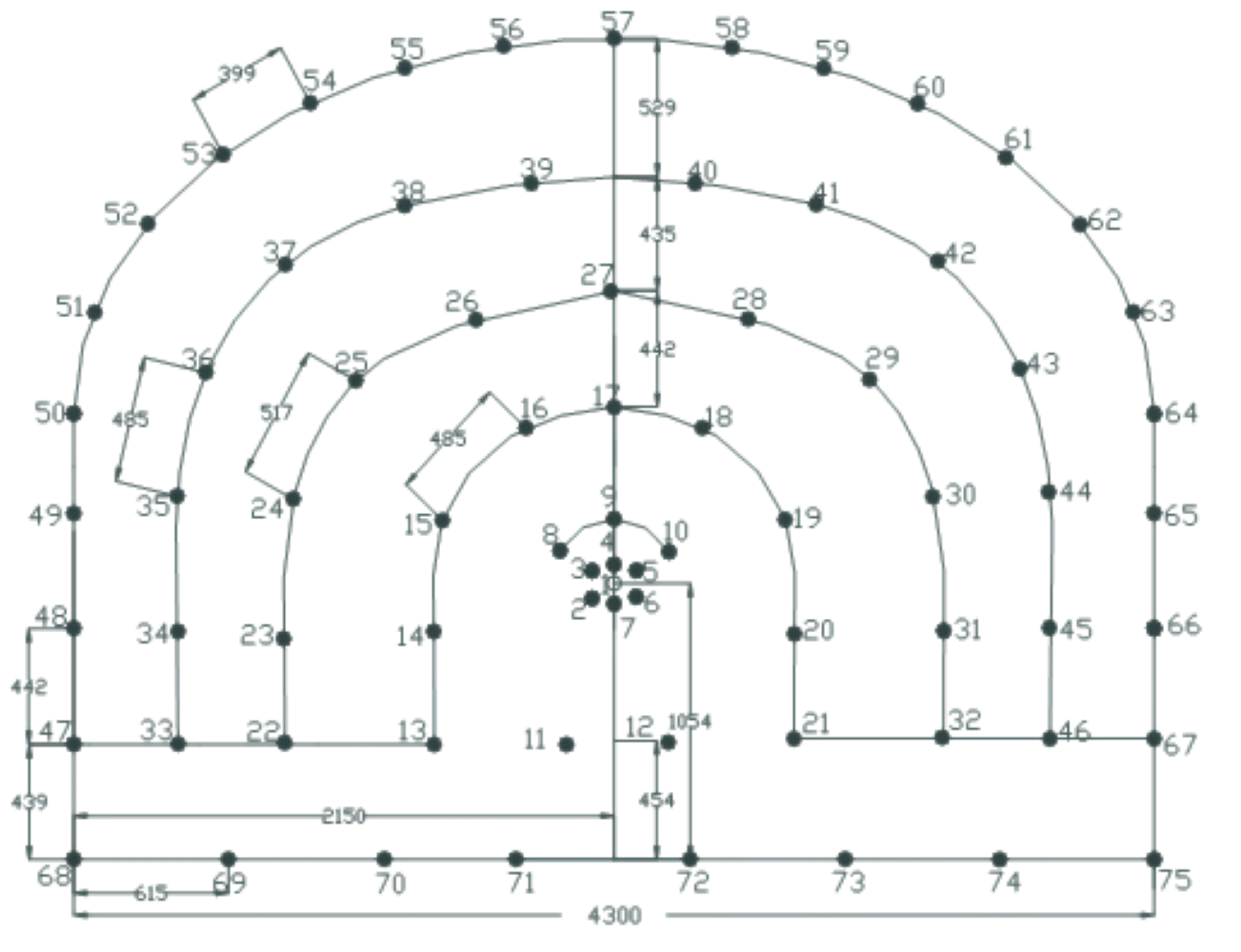
According to the geological conditions, blasting plans are designed, as shown in Fig. 1 and Table 1. It covers the space arrangement of all boreholes, the charge of each borehole and the detonator stages. It needs to be explained that the cutting way used here is the straight parallel cutting [17].
The emulsion explosive is used in the surrounding blasting holes to be cut into several segments on average, using air spacing with uncoupled charge. The weight of each volume of explosive is 300 g. And the blasting vibration monitoring designed has been located in front of the drilling and blasting face. In order to study the damage degree and blasting vibration effect of different blasting parameters on rock mass, each cycle footage should be kept the same, which means 2 m.
A millisecond delay with non-electric detonator is used to detonate, and the cutting holes adopt continuous coupling charge, the auxiliary holes and the bottom holes adopt continuous non-coupling charge, the surrounding holes adopt the air interval with non-coupling charge to bind the interval of the explosive to the detonator and then attach the bamboo sheet to the bottom of the hole. The blockage length of the surrounding hole and auxiliary hole is not less than 20 cm, while the cutting hole is not less than 40 cm.
Fig. 1Blasting network diagram
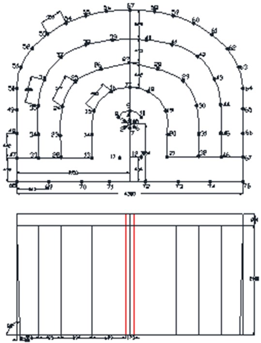
Table 1Blasting parameters table for the scheme
Hole name | Hole No | Number of holes | Charge quantity | Detonator order | |
Explosive volume per each hole | Total weight (kg) | ||||
Empty hole | 1 | 1 | 0 | 0.0 | |
cutting hole | 2-7 | 6 | 3.5 | 6.3 | 1 |
Auxiliary hole | 8-10 | 3 | 2.5 | 2.3 | 3 |
Auxiliary hole | 11-12 | 2 | 2.5 | 1.5 | 5 |
Auxiliary hole | 13-21 | 9 | 2.5 | 6.5 | 7 |
Auxiliary hole | 22-32 | 11 | 2.5 | 8.3 | 8 |
Auxiliary hole | 33-46 | 14 | 2.0 | 8.4 | 9 |
Peripheral hole | 47-67 | 21 | 1.5 | 9.5 | 15 |
Bottom hole | 69-74 | 6 | 3.0 | 5.4 | 15 |
Bottom hole | 68, 75 | 2 | 3.0 | 1.8 | 19 |
Total | 75 | 50.3 | |||
3. Blasting vibration monitoring scheme
In order to accurately predict and control blasting vibration, the in site monitoring has been used here. The main contents of blasting vibration monitoring include the following two aspects. Firstly, to study the propagation and attenuation law of stress waves and the relation between the blasting and the topography and geology. Secondly, to discuss the response characteristics of structure under the blasting vibration wave excitation, to study the relationship between the vibration response characteristics and the blasting mode.
As it is mentioned above, the maximum vibration velocity only measures the instantaneous response of the blasting, and it could not describe the damaged depth of the blasting impact on the surrounding rock. After all, the rock damaged range occupies a property with time effect, which shows a longer time (relative to the instantaneous) accumulation. Meanwhile, the depth of the rock damage at the maximum blasting vibration velocity is often not the ultimate damaged range, but it is usually formed by the subsequent action of explosion shock wave, stress wave and detonating gas.
3.1. Monitoring equipment
As the test and the monitoring has been carried out in the tunnel, its special test environment requires that the test instrument should have the following functions.
(1) as the construction environment is relative bad, water flow is much more and the dust is heavy. The instrument must have the functions of moisture proof and dust proof.
(2) because of limited space, blasting impact is strong. The instrument should be lightweight, portable, strong enclosure and impact resistance.
(3) the vibrometer requires batteries with long power supply.
(4) vibrometer should match corresponding analysis software to facilitate data processing in later stage.
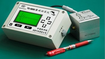
According to the above requirements, TC-4850 blasting vibration recorder produced by Chengdu Zhongke Measurement and Control Co., Ltd. is selected, as shown in Fig. 2.
Fig. 2Schematic of the blasting vibration monitoring system TC-4850
The main index of the recorder system is shown in Table 2.
Table 2Technical index of the blasting vibration monitoring system TC-4850
Index | Parameter | Index | Parameter |
Number of channels | Parallel three channel | Record time | 1-160 second adjustable |
Display mode | All LCD display | Trigger mode | Internal external trigger |
Power supply mode | Built in rechargeable lithium battery | Accuracy of reading | 1 ‰ |
Sampling rate | 1 kHz-50 kHz, Multifile adjustable | Clock precision | ≤ 5 seconds per mouth |
A/D resolution | 16Bit | Data interface | USB 2.0 |
Frequency Response | 0 Hz-20 kHz | Battery life | ≥ 60 hours |
Acquisition mode | Parallel three channel acquisition, multi group cascade | Weight | 1000 g |
Range | Adaptive range, maximum input value 20 V (70 cm/s) | Recording precision | 0.05 mv (0.5 mm/s) |
Trigger way | Continuous trigger record up to 128-1000 | Environment | 10-75 °C, 20-100 % RH |
Trigger level | 0-10 V (0-35 cm/s) Arbitrarily adjustable | Size | 168 mm×99 mm×64 mm |
3.2. Principle of Blasting vibration monitor
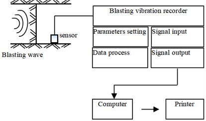
When the blasting occurs, the vibration wave will propagate outward along the rock medium. If the vibration wave is received by the vibrator, the voltage will be produced. When the voltage signal is greater than the trigger level, the vibration signal will be automatically recorded by the blasting vibration recorder. The signal collector will adjust the input signal according to the setting of the instrument. Then it is stored in each channel after A/D conversion. When the data stored exceeds the maximum capacity of the memory, it will overlay the original data. The computer can be connected through USB interface for data analysis and copy.
The instrument consists of an independent acquisition module and an internal computer system. It means that each module contains a time-based controller and four acquisition channels. The modules are synchronized by clock to ensure simultaneous triggering and recording of all channels. The acquisition channel stores the collected data into their respective memory, and CPU accesses the specified channel data through a unified system, and controls the parameters of each acquisition module. As each channel has 16 bits A/D and memory, the phase difference between channels can be neglected in parallel acquisition. The instrument and testing principle are shown in Fig. 3.
After the in site monitoring is finished, testing data is connected to the computer through the USB interface of the instrument. The data is analyzed and processed by the professional software. Before the blasting vibration acquisition device is used, it should be firstly to estimate the basic characteristics of the collected signal, such as frequency range, amplitude range etc. Then, the acquisition parameters such as sampling rate and range could be set.
Fig. 3Block diagram of blasting vibration monitoring system
3.3. Blasting vibration test scheme
Usually, the blasting vibration velocity is subject to the vibration monitoring scheme. How to place the blasting vibration sensors and where to arrange them are significant. It could be performed as follows.
Firstly, to estimate the distribution of vibration intensity on the roadway excavation section, and the most powerful location of blasting vibration could be found out.
Secondly, according to the previous data analysis, it is considered that the blasting vibration speed at the top of the roadway is the largest. It means that the top vibration resistance of the roadway is the worst. Therefore, there are three blasting vibration velocity sensors are arranged on the top of the roadway, and the sensor is arranged at the side wall of the roadway at the same position. In which, a three direction sensors are placed at each measuring point, corresponding to the radial, vertical, and tangent directions. The base is fixed on the rock surface by lime powder coupling. As it is shown in Fig. 4 and Fig. 5.
Fig. 4Installation of blasting vibration meter for measuring the top point
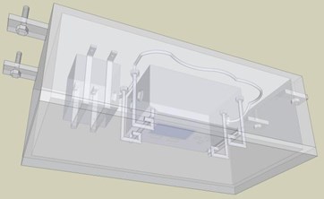
Fig. 5Installation of blasting vibration meter for measuring the side point
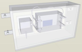
Fig. 6Layout diagram of blasting vibration observation point of roadway roof and side wall
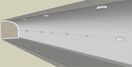
Thirdly, the first measuring sensor point is arranged 10 m away from the blasting face, and the other sensors are arranged at intervals of 5 m. That is, three sets of sensors and six measuring points are linearly arranged along the top and side of the roadway from the blasting face. As it is shown in Fig. 6.
The damage of blasting vibration to surrounding rock is different due to the difference of each charging parameter, cutting way and geological condition.
The maximum value of blasting vibration velocity generally appears at the position of maximum tensile stress, while the position of maximum tensile stress of excavation roadway is generally at the top of roadway. Therefore, one of the vibration velocity sensors has been installed at the top of roadway.
Therefore, the measuring points of blasting vibration are closely followed after each blasting cycle, and the distance between the sensors and the blasting face and the sensors of each measuring point are consistent with the former blasting cycle. Only this, the same objective condition of test data could be ensured and each blasting vibration value is more comparable.
Meanwhile, the instrument needs to be pretested carefully before blasting vibration test, and the blasting vibration test procedure is referred to the blasting vibration detection instruction.
4. Blasting vibration monitoring test
The geological disposal facilities of high-level radioactive waste extend from the surface to a certain depth in the deep underground, which requires that the surrounding rock damage caused by the excavation is as small as possible, because the fracture of the surrounding rock will continue to initiate, expand, or even interconnect in the rock mass, resulting in the loss of the disposed nuclear waste in a certain period of time, which is absolutely not allowed.
The accurate characterization of each blasting parameter can be realized by the blasting vibration monitoring, and then the blasting parameters can be optimized later.
4.1. Blasting vibration test process
The key to complete the blasting vibration monitoring depends on whether the monitoring system selected is reliable and whether it can fully meet the requirements of blasting vibration or not. Therefore, the frequency range and amplitude range of the monitored signal should be estimated and grasped in advance. And then the suitable blasting vibration recorder can be chosen.
The TC-4850 blasting vibration recorder produced by Chengdu Zhongke Measurement & Control Co., Ltd. is used in this test. The radial, vertical and tangential direction data can be obtained through the data acquisition equipment, which can reflect the characteristics of blasting vibration signals more comprehensively. The sensors’ installation position on the rock surface must be kept smooth. The harmonic binder is generally bonded with lime paste, and the vibration measuring sensors are fixed at the corresponding test positions to ensure that the sensors are fixed and not easy to fall off.
It should be observed that there is no gap between the vibration measuring sensors and the rock wall, so that the blasting vibration data can be directly transmitted to the vibration measuring system through the vibration of the rock wall induced by the blasting.
The connecting wire is drawn out from the vibration measurement sensor, and the blasting vibration monitoring equipment is installed. The corresponding protective measures are given to the monitoring equipment to prevent the blasting shock wave and the blasting flying stone damage. Turn on the monitoring equipment, set the frequency range and the amplitude range of the monitoring, and then wait for the blasting to start.
The blasting vibration data are recorded automatically. The monitoring equipment and the vibration measurement sensors are taken out after the blasting operation. The blasting vibration data is derived and data analysis and processing are carried out with the corresponding data software on the computer.
4.2. Blasting vibration data
Three vertical values of particle vibration should be simultaneously measured during the blasting vibration monitoring.
The direct analysis method of blasting vibration signals has been applied to analyse the measured blasting waveform, so the blasting vibration characteristic quantity is determined from the waveform diagram.
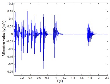
The vibration waveform of each component for one monitoring sensor are shown in Fig. 7.
Fig. 7Vibration waveforms of component for one monitoring sensor
a) Vibration waveform of radial component
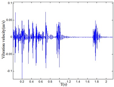
b) Vibration waveform of vertical component
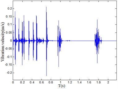
c) Vibrational waveform of tangential component
For each blasting cycle, the vibration instrument test parameters should be kept the same. And the acquisition parameters are used to maintain a uniform vibration test condition.
The maximum particle vibration velocity at the distance 10 m away from blasting source can be obtained by changing the designed blasting parameters. For the straight hole cutting method adopted in this experiment, the maximum vibration velocity is 25 cm/s.
It can be seen from Fig. 7 that under the condition of different detonators delay, the trend of the blasting vibration velocity changes with time is clear, and the peak value of vibration velocity is in a fine agreement with the detonator section. At the same time, the blasting vibration velocity is controlled within a reasonable range, which should be within 30 cm/s. It illuminates that the blasting vibration of the BET structure is controllable.
Moreover, the blasting parameters design is also reasonable, especially the explosive charge and detonator section are representative.
4.3. Blasting vibration attenuation law
According to the monitoring results of blasting vibration, the accurate influence coefficient and attenuation index can be obtained by the least square fitting with the Sodev’s empirical formula. The concrete regression fitting process is as follows:
In which, is the blasting vibration velocity, is the maximum explosive quantity, is the distance between the blasting source and the monitoring site.
Logarithm the left and right sides of Eq. (1), then it is obtained:
Order , then there is:
Furthermore, setting , , , the original formula transfers as a linear equation, it follows as:
For each group of monitoring data, , and are determined, and the estimated values of and based on the and can be obtained by the least square method:
In which: , .
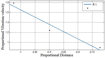
During the blasting cycle, the fitting curves at each measuring point on the tunnel vault using the Sodev’s empirical formula are shown in Fig. 8.
Fig. 8Velocity fit on the tunnel vault (correlation coefficient = 0.93498)
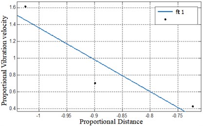
The blasting vibration velocity data arranged at the side wall were simultaneously monitored. The fitting curve is shown in Fig. 9.
According to the fitting formula, the and values in Sodev’s empirical formula can be calculated as 125 and 1.32 respectively, in which it shows that the rock mass in the tunnel belongs to a hard rock, and it also has proven that the above blasting scheme is feasible and rational.
Fig. 9Velocity fit on the tunnel side wall (correlation coefficient = 0.9326)
4.4. Vibration damping method
Based on the above understanding of blasting vibration characteristics, the vibration reduction and damping method in this project is put forward.
(1) millisecond blasting. A large blasting source is transformed into several small blasting sources. In view of the disturbance and separation of blasting vibration signals, the blasting vibration intensity is greatly reduced and the main vibration frequency is correspondingly increased under the condition that the total explosive charge is invariable. Thus, the damage effect of blasting vibration is reduced. It can be controlled by the delay of detonators.
(2) pre-splitting blasting. Because the propagation of blasting vibration wave will stop at the interface of air interval, a certain depth of groove or pre-splitting surface could be excavated between the blasting source and the protective object. Although the diffraction effect of blasting vibration wave cannot be prevented by the pre-splitting surface, the Rayleigh wave on the ground surface will be greatly weakened, thus greatly reducing the blasting vibration effect.
(3) avoid slag blasting. Slag blasting can effectively improve the quality of blasting and crushing. However, when the blasting vibration safety is considered, as there is a large amount of slag before the blasted body, which will strengthen the restraint of it, so that there would be more vibration energy can be transferred into the rock mass, which will have a negative vibration impact on the protective object. Therefore, in order to reduce the vibration hazards, the bottom ridge should be cleaned up, so that the blasted rock could be smoothly pushed along the direction of the minimum resistance line.
(4) control the main vibration frequency. Under the same blasting vibration intensity, the lower the main vibration frequency, the closer to the natural frequency of the protective object, and the greater the possibility of causing damage to the object. The main vibration frequency can be effectively increased by reducing the maximum explosive charge and shortening the delay time, so as to improve the blasting vibration safety.
(5) vibration reduction using interference. Since the vibration wave arriving at the protective object can reduce the vibration intensity when the peak and valley intersect, the vibration can be reduced by setting the delay interval in half period. However, it is difficult to determine the appropriate interval time because there is more than one protective object in each blasting cycle, the distance is also different, and the main vibration frequency varies uncertainly. In addition, even if the appropriate interval is found, the delay accuracy of the ordinary detonator is at least 10ms, which the desired precise delay control cannot be achieved, so that the vibration reduction is basically in a theoretical level. With the development of electronic detonation technology, high-precision time delay control has been realized.
(6) vibration reduction by buffering blasting. In the late 1990s, it was put forward that a section of air was reserved at the bottom of the hole to avoid the direct action of explosive wave on the bottom. While the rock mass at the bottom would still be destroyed by the detonation gas. So, the vibration energy was weakened.
5. Conclusions
1) In order to study the blasting vibration effect deeply, a blasting test with the blasting vibration monitoring has been focused here. Based on the engineering demand of High-level radioactive waste geological disposal, the smooth blasting parameters of BET project have been designed. Meanwhile, the blasting vibration monitoring scheme are devised.
2) From the point of the blasting vibration monitoring scheme, the blasting vibration monitoring has been carried out. It was found that the peak vibration velocity was controlled within a reasonable range.
3) The vibration attenuation law has been analyzed using the Sodev’s empirical formula, which shows that the blasting parameters design and vibration monitoring scheme were reasonable. And it illuminated that the blasting parameters were proved to be reasonable and desirable. Finally, the vibration reduction measurements for this project have been put forward.
This study has a significant guidance for the High-level radioactive waste geological disposal. Obviously, the result and the theoretical knowledge could be applied to the blasting and excavation of other geo-engineering.
References
-
“Medium and long-term plan for National Nuclear Power Development (2005-2020),” (in Chinese), National development and Reform Commission., 2007.
-
“Regulations on the Management of Radioactive Wastes (GB14500-93),” (in Chinese), Ministry of Environmental Protection of the People’s Republic of China, State Technical Supervision Bureau, 1993.
-
“Siting of radioactive waste geological disposal (HAD401/06),” National Nuclear Safety Agency, 1998.
-
“People’s Republic of China, law of prevention and control of radioactive pollution,” (in Chinese), Law Press, 2003.
-
“Guidelines for Research and Development Planning of Geological Disposal of High-level Radioactive Wastes,” (in Chinese), National Defense Science, Technology and Industry Commission, Ministry of Science and Technology, State Environmental Protection Administration, 2006.
-
Z. Pan, Q. Q. Hu, “Strategic study on geological disposal of high-level radioactive waste,” (in Chinese), Atomic Energy, 2009.
-
Qian Qi Hu, “New progress in rock engineering technology in China,” (in Chinese), Chinese Engineering Science, Vol. 12, No. 8, pp. 37–48, 2010.
-
D. X. F., J. B. Zhu, Chen, S. G. Zhao, Y. X. Zhou, and J. Zhao, “Numerical study on tunnel damage subject to blast-induced shock wave in jointed rock masses,” Tunnelling and Underground Space Technology, Vol. 43, No. 88-100, 2014.
-
H. Xie, J. Zhu, T. Zhou, K. Zhang, and C. Zhou, “Conceptualization and preliminary study of engineering disturbed rock dynamics,” Geomechanics and Geophysics for Geo-Energy and Geo-Resources, Vol. 6, No. 2, pp. 1–14, Jun. 2020, https://doi.org/10.1007/s40948-020-00157-x
-
X. Xiang et al., “Numerical analysis of explosive load of single hole blasting and multiple-hole simultaneous blasting in rock mass,” (in Chinese), Chinese Journal of Rock Mechanics and Engineering, Vol. 26, pp. 3390–3396, 2007.
-
L. H. Tang Hai, “Analysis for blasting vibration attenuation law in groundwork digging in the second stage project in Lingao Nuclear Power Station,” Blasting, Vol. 25, No. 4, pp. 88–91, 2008.
-
X. Xiang et al., “Research on vibration safety threshold for rock under blasting excavation,” (in Chinese), Rock and soil Mechanics, Vol. 29, No. 11, pp. 2945–2952, 2008.
-
Xia Xiang, Li Haibo, Zhang Dayan, et al., “Safety threshold of blasting-induced rock vibration for Honyanhe nuclear power plant,” Explosion and Shock Waves, Vol. 30, No. 1, pp. 27–32, 2010.
-
C. González-Nicieza, M. I. Álvarez-Fernandez, A. E. Alvarez-Vigil, D. Arias-Prieto, F. López-Gayarre, and F. L. Ramos-Lopez, “Influence of depth and geological structure on the transmission of blast vibrations,” Bulletin of Engineering Geology and the Environment, Vol. 73, No. 4, pp. 1211–1223, Nov. 2014, https://doi.org/10.1007/s10064-014-0595-7
-
D. W. Lee, S. H. Kim, “An analysis of the results of trial blasting of site development project in the volcanic island,” International Science Index, Civil and Environmental Engineering, Vol. 10, No. 12, pp. 1534–1539, 2016.
-
H. Li, X. Li, J. Li, X. Xia, and X. Wang, “Application of coupled analysis methods for prediction of blast-induced dominant vibration frequency,” Earthquake Engineering and Engineering Vibration, Vol. 15, No. 1, pp. 153–162, Mar. 2016, https://doi.org/10.1007/s11803-016-0312-6
-
K. Man, X. Liu, J. Wang, and X. Wang, “Blasting energy analysis of the different cutting methods,” Shock and Vibration, Vol. 2018, pp. 1–13, Dec. 2018, https://doi.org/10.1155/2018/9419018
About this article

This work was supported by the National Natural Science Foundation of China [Grant Nos. 51522903, 51774184], Excellent project Fund in North China University of Technology [Grant No. 216051360020XN199/006] and Scientific Research Fund in North China University of Technology [Grant No. 110051360002].
