Abstract
The durability tests are most important for mechanical system development in term of their correct functionalities during life-cycle period. The mechanical vibration tests are mandatory for crucial mechanisms like brakes, chassis and direction control parts etc. Transportation producers have to fulfil durability standards which are defined as power spectral density spectrum of mechanical excitation in three axes. The spectrum of mechanical vibration is prescribed as the input to the system and has to be observed during whole tests. The hydrodynamic valves as exciters are more suitable than electromechanical system cause of higher capacity load. The disadvantage might be the controlling of the prescribed spectrum cause of their natural frequencies and the friction between the piston and cylinder. Those two deficiencies are possible to solve by using iteration control method and no gasket system with suction of the hydraulic oil.
1. Introduction
Hydrodynamic cylinders used as vibration exciter evince couple of issues which have to be solved to provide the acceptable functionality. The first precondition is to reduce the friction between piston and cylinder as possible. The friction influence is very significant for controlling the hydraulic system and causes the non-stability in high frequencies with low amplitude. The next precondition is the relevant servo-valve with satisfactory response characteristic in terms of prescribed power density spectrum of the vibration tests. The control system of the hydraulic servo-valve is based on common proportional-integral-derivate regulation. The basic setting is mostly set by the cylinder provider or is possible to use common transient identification or harmonic signal validation methodologies. The PID (proportional-integral-derivate) regulation is the common control loop scheme which calculates an error value as the difference between a measured process variable and a desired value. This regulation control is suitable for transient response tests, the setting of proportional and integral component is possible to optimize regulator to the specific assignment. In case of harmonic desired signal is possible to modify the proportional component to fulfil the entered amplitude value. The time domain iteration method evaluates in each time step the variation of desired and entered amplitude and cause of zero crossing and priority on the amplitude the iteration needs the couple of periods to get the acceptable results.
The durability standards prescribe in most cases the power spectral density spectrum as the function of frequency and it has to be fulfilled in each time step during the test. The input signal of the mechanical vibration is the noise signal with Gaussian normal distribution. The time domain iteration is not possible to use for noise signal and is necessary the different sophisticated approach. The optimization variable is the magnitude of the input signal as in time domain but the control system compares the frequency response based on the identified model. The methodology evaluates the frequency response model in the first step cause of decreasing the count of iteration steps. The identification uses the noise signal in frequency range of prescribed spectrum. If the hydrodynamic system evinces the natural frequency in the prescribed frequency range (most cases) the iteration is highly effective. The iteration method in frequency domain uses the displacement in the loop feedback and the acceleration as the control signal for frequency analysis comparison.
2. Time domain iteration
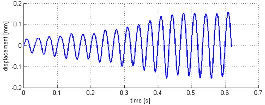
The time domain iteration is used for harmonic signal as the input for mechanical vibration. The modification of the desired value of the displacement, velocity or acceleration needs couple of periods of the harmonic signal to get the entered amplitude value. The signal with amplitude 0.15 mm and frequency 30 Hz is described on Fig. 1. The delay is 12 periods to get the entered amplitude.
Fig. 1Time-domain iteration
3. Frequency domain iteration
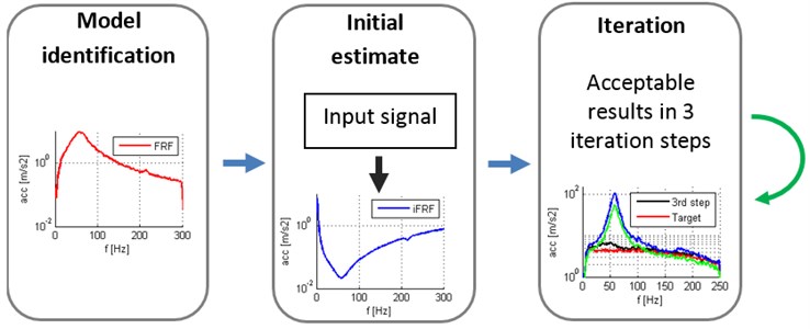
Frequency domain iteration is possible to divide in several parts. The model identification is the first step to get frequency response characteristics of the hydraulic exciter system. The frequency response is used for frequency response function evaluation (FRF) which is represented by internal model of the hydraulic system. The evaluation of the inverse frequency response function is necessary for iteration method. The information about the controlled system and FRF is known already in the first iteration step. It is very helpful to decrease the count of iteration steps. Inverse FRF (iFRF) is used for evaluation of the input signal (prescribed spectrum) response of the model (Fig. 2).
Fig. 2Frequency domain method
It is mandatory to identify the complete exciter system with the testing specimen or mechanism. It is possible to suppress natural frequencies of the hydraulic exciter and also testing specimen or mechanisms. It is recommended to use wider frequency range than prescribed spectrum. The common frequency response function (FRF) of the hydraulic exciter is described on Fig. 3. The next step is the original estimate of the input signal for the first step of iteration (the input signal response of the iFRF). The input signal response and target prescribed spectrum are described in Fig. 4.
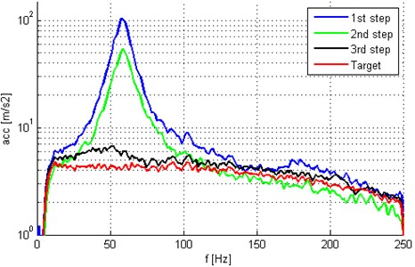
Input signal response evinces the significant decline around the natural frequency. It is caused by the iFRF function of the system because around natural frequency is necessary to decrease the input energy and the system performs like an active damper. The frequency domain iteration is effective in couple of steps and results are described in Fig. 5.
Fig. 3FRF and iFRF of the model
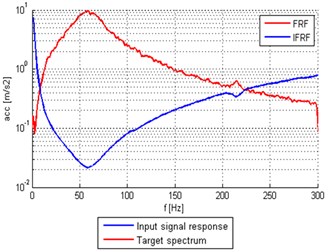
Fig. 4Input signal response and target spectrum
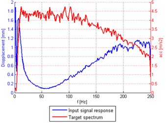
Fig. 5Frequency domain iteration steps and target spectrum
The important roles in fulfilling the standards have also other components of the whole hydraulic systems. The main role is the performance of the hydraulic aggregate described by operating pressure and maximum flow rate. The hydraulic cylinder and proportional valve are chosen based on the knowledge of used hydraulic aggregate.
Fig. 6Prescribed power density spectrum and test results
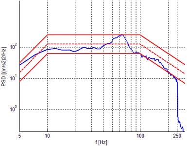
The common prescribed power density spectrum and the results of the test using frequency iteration method describe Fig. 6. The power density spectrum is in range from 5 to 250 Hz. The results are in ±3 dB limits with maximum mass 50 kg. It is ordinary that standards prescribe also limits in dB which have to be fulfilled. The prescribed spectrums can be different in dependence on the direction of mechanical vibration.
The proportional valve evinces also limits in frequency range and frequency response but there is possible to fulfil standards with low weight testing samples and low power spectral density spectrums till 1 kHz by using hydraulic exciters. There is possibility to use couple of proportional valves with one hydraulic cylinder to increase the flow rate at high frequencies. The influence on mass of the testing specimen is described on Fig. 7.
Fig. 7Specimen mass influence
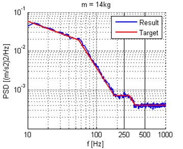
a)
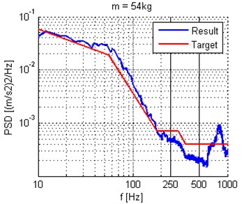
b)
The influence on mass of the specimen is important in term of fulfilling power density in high frequencies. The proportional valve is not possible to deliver enough of oil to hydraulic cylinder chamber and occurs to attenuation from about 200 Hz. The peak on the end of the spectrum around 800 Hz is caused by “hydraulic noise” and it is very difficult to suppress this phenomenon because the proportional valve is at the limit of efficiency.
4. Conclusions
The main aim is to decline the influence of the hydraulic exciter on the testing specimen of mechanisms. The advantage of using hydraulic cylinder as exciters is their small size combined with maximum force. The disadvantage might be the lower frequency range. The natural frequencies of hydraulic exciter are possible to suppress by time domain iteration for harmonic signal and frequency domain iteration for pseudo random signals with prescribed power density spectrums. It is necessary to take into account capacity of the hydraulic aggregate, response of the proportional valve etc. It is necessary to identify the hydraulic system by using FRF and iFRF function before the test. The results for prescribed standards have to be fulfilled in limits and by using frequency domain iteration is it possible to get acceptable results in couple of iteration steps.
References
-
Yung-Li Lee Fatigue Testing and Analysis, Theory and Practice. Elsevier, 2005.
-
Zeman V., Hlaváč Z.Vibration of mechanical systems, FAV ZČU v Plzni, Plzeň, 2004.
-
Ewins D. J. Modal Testing: Theory and Practise. Bruel & Kjaer, 1985.
About this article

