Abstract
Paper describes phenomena related to the vehicle acceleration at the curve, with the high speed, close to the maximal possible speed. The phenomena were investigated with three tools: classical analytical mechanics, computer simulation and tests with physical model. The goal was the comparison of standard 4×4 driveline with unconventional patented 4×4 driveline called diagonal one.
1. Introduction
Drivelines of cars in current shape (2010) are the result of many year’s evolution. However, the history of cars lasts longer than 100 years, dynamic development of four wheels driven passenger cars started in the eighties [1-6]. Such a propulsion system indicates many advantages in comparison with one driven axle. The most essential factor is safety and in this aspect 4wd exceeds all the other solutions. Contemporary 4wd drive lines in spite of a big variety of design solutions and operating rules have one common constructional feature. Wheels of each particular axle are connected together by means of one of many differential gears. That is the problem. Such a design precludes a priori power distribution optimisation. Observations of rally cars led to conclusions that resulted in new approach to the manner of power distribution. The reasoning is as follows:
Assuming some simplifications, it can be stated that during uniform motion of the car all resistance forces result in under loading of the front axle and overloading of the rear axle. Such a layout of forces results in lifting the front part of the vehicle shown in the Fig. 1.
Fig. 1Front part of the vehicle
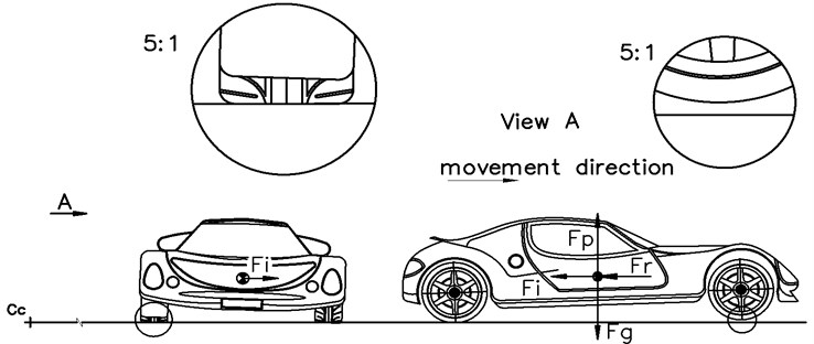
It can be assumed that all the resistance forces act as a single force presented by vector acting in the centre of the mass point. In case of uniformly accelerated motion an inertial resistance force and resistance of rotating masses will appear. Both of them are presented by vector . Like force both forces have the same direction and sense. To simplify the drawing the vehicle moves at the horizontal road. If resistance of the hill appears it will be represented by a vector acting in the centre of mass. Force created by propulsion system, does not matter if comes from front or rear axle (or from both axles), results in underloading of front the axle and overloading of the rear axle. These propulsion forces are presented by vector . This vector is directed upward as the result of propulsion torque.
During the move of the car on the curve, apart from all the forces mentioned above centrifugal force and its reactions appear. This force is represented in the Fig. 1 as a vector . Appearance of centrifugal force results in increased pressure of external wheels to the ground and decreased pressure of internal wheels. As internal wheels are understood as wheels located closer to the centre of the curve . The limits of this phenomenon is slide or turnaround of the vehicle. All the mentioned forces and springy suspension of the car lead to the situation in which front internal wheel loses contact with the ground. Such a situation is presented in Fig. 1. The turnaround of the car happens exceptionally.
As the result of observation and forces analysis some conclusions were expressed:
a) During accelerating on the curve the rear external wheel of the vehicle exerts the biggest pressure on the base thus this wheel is able to transfer the biggest propulsion force.
b) During accelerating on the curve the front internal wheel of the vehicle exerts the smallest pressure on the base thus this wheel is able to transfer the smallest propulsion force.
c) Taking into consideration statement a and b it seems to be desirable to transfer part of propulsion force from front internal wheel to the rear external wheel. This part is the force that cannot be transfer to the base by front internal wheel.
Contemporary commercially manufactured drivelines are not able to do so. In such a situation author of this paper elaborated new conception of driveline in which wheels are connected mechanically diagonally. This solution was patented in Poland in 2007 as “propulsion system for motor vehicle” patent number PL 194829. This new driveline is called diagonal one.
2. Research
It can be assumed that all the resistance forces act as a single force presented by vector acting in the centre of the mass point. In case of uniformly accelerated motion an inertial resistance force and resistance of rotating masses will appear. Both of them are presented by vector . Like force both forces have the same direction and sense. To simplify the drawing the vehicle moves at the horizontal road. If resistance of the hill appears it will be represented by a vector acting in the centre of mass. Force created by propulsion system, does not matter if comes from front or rear axle (or from both axles), results in underloading of front the axle and overloading of the rear axle. These propulsion forces are presented by vector . This vector is directed upward as the result of propulsion torque.
During the move of the car on the curve, apart from all the forces mentioned above centrifugal force and its reactions appear. This force is represented in the Fig. 1 as a vector . Appearance of centrifugal force results in increased pressure of external wheels to the ground and decreased pressure of internal wheels. As internal wheels are understood as wheels located closer to the centre of the curve . The limits of this phenomenon is slide or turn around of the vehicle. All the mentioned forces and springy suspension of the car lead to the situation in which front internal wheel loses contact with the ground. Such a situation is presented in Fig. 1. The turn around of the car happens exceptionally.
As the result of observation and forces analysis some conclusions were expressed:
a) During accelerating on the curve the rear external wheel of the vehicle exerts the biggest pressure on the base thus this wheel is able to transfer the biggest propulsion force.
b) During accelerating on the curve the front internal wheel of the vehicle exerts the smallest pressure on the base thus this wheel is able to transfer the smallest propulsion force.
c) Taking into consideration statement a and b it seems to be desirable to transfer part of propulsion force from front internal wheel to the rear external wheel. This part is the force that can not be transfer to the base by front internal wheel.
Contemporary commercially manufactured drivelines are not able to do so. In such a situation author of this paper elaborated new conception of driveline in which wheels are connected mechanically diagonally. This solution was patented in Poland in 2007 as “propulsion system for motor vehicle” patent number PL 194829. This new driveline is called diagonal one.
Fig. 2The 3D model in NX5 environment
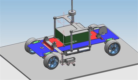
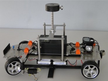
Virtual and physical tests were performed using Mechatronic Test Vehicle – MTV. Virtual model was created and tested in Unigraphics NX5 environment. Physical model was based on 2D technical documentation based on 3D model (Fig. 2). The 3D model is visible in Fig. 2 in NX5 environment. Fig. 3 shows physical model placed on special frame that protects rubber wheels from deformation when idle. Both models were used for testing the case of vehicle acceleration on curve.
Fig. 3MTV placed on the frame
3. Conclusions
Theoretical analysis of vehicle wheels vertical load during accelerating on the curve indicates that external rear wheel bears the biggest vertical force. The front internal wheel is loaded with the smallest vertical load. The classic 4wd transmission system is not able to transfer the surplus propulsion force from unloaded front wheel to the overloaded placed on diagonal side of the vehicle rear wheel. Such a possibility is the main feature of diagonal transmission system. Initial virtual model and physical tests confirm the potential of the new method of power distribution. In some test conditions higher maximal speed for the diagonal transmission was observed.
There is a possibility of diagonal transmission system application for sport vehicle to improve performance or for utilitarian vehicles for safety improvement, specially with ESP applications. When it comes to special vehicle both mentioned above features are desired and in addition the conception of power-pack is an additional advantage.
Described research is a very first attempt of solution that was created as the result of observation and intuition. Diagonal transmission needs further research in virtual reality as well as physical tests to prepare recommendation for design to continue tests in real vehicle.
References
-
Mitschke M. Car dynamic. Warsaw: WKŁ, 1977.
-
Prabakar R. S., Sujatha C., Narayanan S. Response of a quarter car model with optimal magnetorheological damper parameters. Journal of Sound and Vibration, Vol. 332, Issue 9, p. 2191-2206.
-
Zhenguo Zhang, Zhiyi Zhang, Xiuchang Huang, Hongxing Hua Stability and transient dynamics of a propeller-shaft system as induced by nonlinear friction acting on bearing-shaft contact interface. Journal of Sound and Vibration, Vol. 333, Issue 12, p. 2608-2630.
-
Frangos C., Yavin Y. Control of the motion of a small-scale car with four steerable wheels. Computers and Mathematics with Applications, Vol. 48, Issues 3-4, p. 437-453.
-
Ming Foong Soong, Rahizar Ramli, Wan Nor Liza Wan Mahadi Vehicle suspensions with parallel inerter: effectiveness in improving vibration isolation. Journal of Vibroengineering, Vol. 16, Issue 1, 2014, p. 256-265.
-
Yiguo Xue, Shucai Li, Dunfu Zhang, Xiaojing Sun, Zheng Sun, Yiguo Nie Vibration characteristics and environmental responses of different vehicle-track-ballast coupling systems in subway operation. Journal of Vibroengineering, Vol. 16, Issue 5, 2014, p. 2458-2473.
-
Fajer A. Research upgraded the drivetrain in race cars. Master thesis, Department of Mechatronics and Design Engineering Systems, Silesian University of Technology, 2009.
-
Help Unigraphics NX software.
-
Mydlarz J. Tank Modernization Drive T-72. New Military Technology 9, 1998, p. 20-23.
-
Information materials TRANSMISIE S.R.O. – ALIGATOR 4X4 Master presentation.
-
Baier A., Majzner M., Jamroziak K. Analysis of railway wagon movement on a curvet track. The Journal of Science of the Gen. Tadeusz Kosciuszko Military Academy of Land Forces, Vol. 4, Issue 158, 2010.
-
Baier A., Żółkiewski S. Epoxy and polyester warp laminates testing on abrasive wear. Maintenance and Reliability, Vol. 15, Issue 1, 2012, p. 37-43.
-
Buchacz A., Baier A., Świder J., Jamroziak K., Majzner M., Żółkiewski S., WRÓBEL A. Experimental Tests of Chosen Fibre-metal Laminates. Silesian University of Technology Press, Gliwice, 2012.
-
Kardas-Cinal E., Zboiński K. Investigation of safety of a railway vehicle in the presence of random track irregularities. Proceedings of the 10th Mini Conference on Vehicle System Dynamics, Identification and Anomaliesî, Budapest, Hungary, 2006, p. 169-176.
About this article

The work was carried out under the project number PBS2/A6/17/2013 realized as a part of the Applied Research Program, funded by the National Research and Development Centre.
