Abstract
Bolted joint is a commonly used complex flexible interface in machine tools. The stiffness influential factors-based dynamic model provides a high accuracy modeling method of bolted joints in machine tools. The key of wide application of this method is the database of the stiffness matrices of bolted joints under different conditions. This paper mainly concerns the contact stiffness of bolted joints with different material combination in machine tools and tries to establish the relationship of them. Using the stiffness influential factors-based dynamic modeling method, the contact stiffness of bolted joint is expressed as the stiffness matrix of the connection finite element. After impact modal tests were carried on the specimens, stiffness matrices of bolted joints with different material combinations are identified from the frequency response functions. The ratio of the stiffness matrices validates the effectiveness of the conclusion that the contact stiffness of bolted joints with different material combination is proportional to the corresponding equivalent elastic modulus deduced from Hertz contact theory. The reliable proportional relationship provides a great convenience to the wide application of the stiffness influential factors-based dynamic modeling method of bolted joint.
1. Introduction
Bolted joint is wide used in machine tools, ships, automobiles, aerospace and bridge structures and the performance of bolted joints significantly affects the static and dynamic response of those structures due to the fact that the added flexibility of the assembled strucutures caused by the bolted joint is heavy. The proper representation of bolted joint is the key to obtain the accuracy static and dynamic response of those assembled structures. At present, the finite element analysis is a popular and effective method to predict the characterictics of the structures. However, there is not an available effective model of bolted joint in the commercial finite element package. During the past many decades, many works have addressed the issue of the model of bolted joint. There are three popular modeling methodologies in literatures. The first is the direct finite element model, for example, the three dimensional (3D) detailed finite element model as presented in [1-7], the elastoplastic element pair [8], a combination of linear and nonlinear springs with a viscous damper [9], two-node connector elements [10], a combination of beam elements coupled to rigid contact surfaces [11], the spring-based model [12, 13]. In the second methodology, the bolted joint was presented by a thin layer of elasto-plastic material [14] or a layer elastic virtual material [15]. The third is the combined experimental-analytical model, for example, the GW model [16], the spring-damper model [17, 18], the isoperimetric contact elements model [19], the stiffness influential factors-based modeling method [20], generally, there is parameter identification included in this methodology. All of the models were attempted to understand the basic physics of bolted joints, as proposed in [21], the models should be physics based. Nevertheless, it is not an easy work because of the complexity of bolted joints.
The static and dynamic response of bolted joints is affected by many factors. Several researches have been done on the issue. Salih and Patil [22] investigated the effects of material properties, tensile load, adhesive thickness, bolt diameter and over lap on the load transfer in bolted joint. Khashab et al. [23] studied the influence of the tightening torque and the washer outer size on the strength of bolted joints. Ekh and Schon [24] mentioned that the geometry and material properties of the fastener and the connected components affected the mechanisms of the joint. Huang et al. [25] showed that the principal influential factors of bolted joint dynamic characteristics include material properties of the two connected sub-structures, roughness, geometry shape, contact size, pre-tightening force, media between the mating surfaces and so on. The material properties (elastic modulus, Poisson’s ratio etc.) affect the deformation of the two connected surfaces under external force, so it influences the dynamic characteristics of bolted joint greatly. He [26, 27] investigated the influence of material on free torsional and transverse vibration of the single lap-jointed cantilevered self-piercing riveting (SPR) beams using finite element method (FEM). It showed that the torsional and transverse natural frequencies of the SPR beam increase significantly as elastic modulus increases, change slightly corresponding to the change of Poisson’s ratio, but decrease as mass density increases. Shimizu [28] obtained the contact stiffness of joint with different material combination through quantitative measurement method. His test result indicated that the more the longitudinal elastic modulus is large, the more contact stiffness becomes large.
In literature [20], the author (Kuanmin Mao) and his co-workers proposed the stiffness influential factors-based dynamic model of bolted joints in machine tools. The joints between every two neighboring bolts for the linear connection or every four neighboring bolts for the array connection are considered as a connection finite element. Each of the elements has 8 nodes and every node has 3 degrees of freedom resulting in 24 degrees of freedom in total. The contact stiffness of bolted joint, which is mainly affected by materials, roughness, pre-tightening force and the contact size, is expressed as the stiffness matrix with 24×24 dimension. Through the validated examples presented in the paper, it is proved to provide a high accuracy dynamic modeling method of bolted joints. However, in the prior work, only the bolted joint with the material combination of 45#-45# is studied. The key of wide application of the modeling method in design is the acquisition of the database of stiffness matrices of bolted joints under different conditions, for example, different material combination.
The purpose of this paper is attempted to obtain the reliable relationship of stiffness matrices of bolted joints with different material combination and provide convenience to establish the stiffness matrix database. At first, based on Hertz contact theory, the relationship that the contact stiffness of bolted joint with different material combination is proportional to the corresponding equivalent elastic modulus is obtained. According to the stiffness influential factors-based dynamic model, the contact stiffness of bolted joints with material combinations of HT250-HT250, HT250-45# and 45#-45# which is commonly used in machine tools is studied in the form of stiffness matrix of the connection finite element. The ratios among these stiffness matrices validate the proportional relationship obtained based on the Hertz contact theory is reliable. At the end, the beam-rail bolted connected long beam and the bed-column bolted connected block structure are employed to show the application of the reliable proportional relationship.
2. The proportional relationship of material properties and contact stiffness of bolted joint
In machine tools, two or more components are reliable connected by bolts. There might be dynamic loading in three directions acted on the bolted joint. From the microscopic perspective, the mechanical surface which connected by bolted joint is not a true rigid surface, but composed of a series of asperities with different heights. These asperities can be simplified as many hemispheres with different radius. The contact of the asperities can be thought as a series of hemispheres with different radius in contact. Before the deduction, the following assumptions are adopted: a) the rough surface is isotropic; b) the asperities of surfaces are far apart and there is no interaction between them.
Fig. 1Contact of two rough surfaces which connected by bolted joint
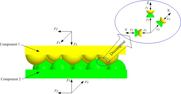
As shown in Fig. 1, when the three directions dynamic loading acted on the two contact rough surfaces, in the contact zone, those asperities undergo elastic and plastic deformation in the three directions, including one normal direction and two tangential directions. Therefore, the contact of two asperities can be decomposed into the contact of two hemispheres with different radius in the three directions. In the normal direction (the direction shown in Fig. 1), the contact of two hemispheres with radius and under loading is shown in Fig. 2. The normal deformation and radius of contact zone [29] will be described by:
where is the equivalent radius of contact and is the equivalent elastic modulus of contact surfaces:
where and are Poisson’s ratios of the two contact components; and and are the Young’s moduli of the two contact components. The normal contact stiffness of the two hemispheres is obtained from Eq. (1) and Eq. (2):
The equivalent radius of contact can be expressed as [30]:
where is the fractal dimension of surface profile, is the fractal roughness parameter and is the area of contact zone. According to literature [31], the relation between , and roughness of the contact surface is expressed as:
Fig. 2The contact of two hemispheres with different radius in normal direction: a) Before deformation; b) After deformation
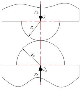
a)
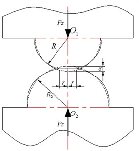
b)
Eqs. (5)-(8) show that the normal contact stiffness of the two hemispheres is decided by the corresponding equivalent elastic modulus, roughness of the contact surfaces and the loading. Further, the normal contact stiffness is directly proportional to the corresponding equivalent elastic modulus.
Based on the two assumptions presented above, the same relationship can be obtained that the contact stiffness in the two tangential directions is directly proportional to the corresponding equivalent elastic modulus. Due to the fact that the material we studied is isotropic, therefore, the conclusion that the contact stiffness in the three directions is directly proportional to the corresponding equivalent elastic modulus of the two contact components. The relationship can be expressed like this:
where and are contact stiffness of bolted joints with material combinations of and . and are the corresponding equivalent elastic modulus. And , , , are the material of the components which are connected by bolts.
3. Stiffness matrices of bolted joint with different material combination
In this study, according to the stiffness influential factor-based dynamic model, the contact stiffness of bolted joint is expressed in the form of stiffness matrix of the connection finite element. The proportional relationship between the contact stiffness and the corresponding equivalent elastic modulus of bolted joint is validated by the stiffness matrices of bolted joint identified from the frequency response functions (FRFs) which are obtained after the impact modal test is carried on the specimens made of different material combinations.
According to our investigation, in machine tools, the most commonly used material of the two components which connected by bolted joint includes HT250 and 45#, where HT250 is a gray iron whose tensile strength is 250 MPa and 45# is a carbon steel whose carbon content is about 0.45 %. Therefore, in this work, the stiffness matrices of bolted joint with material combinations of HT250-HT250, HT250-45# and 45#-45# are studied. According to the dynamic model method proposed in the literature [20], a series of specimens similar to Fig. 3 are designed and manufactured and the corresponding stiffness matrices of those bolted joints are obtained. As shown in Fig. 3, one specimen is composed of two sub-structures which have the same contact size (‘a’ and ‘b’ which is shown in Fig. 3(b)). The sizes and materials of all the manufactured sub-structures are listed in Table 1. So, there are 24 specimens in total. Based on the material combination, those specimens are divided into three groups, eight are HT250-HT250, eight are HT250-45#, and eight are 45#-45#. Some manufactured sub-structures are shown in Fig. 3(c).
Fig. 3a) Structure of the specimen; b) a sub-structure of the specimen; c) some prepared sub-structures
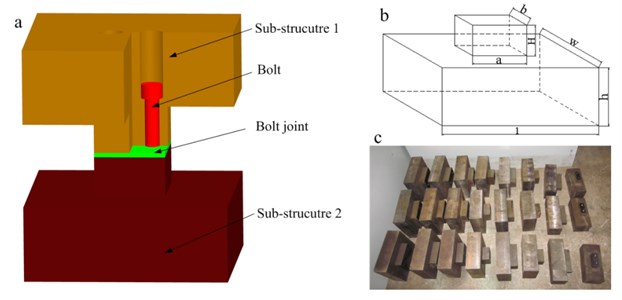
Table 1Information of all sub-structures
No. | (mm) | (mm) | (mm) | l (mm) | (mm) | (mm) | Material |
1 | 80 | 30 | 45 | 230 | 100 | 85 | HT250 |
2 | 80 | 30 | 45 | 230 | 100 | 85 | 45# |
3 | 80 | 63 | 45 | 230 | 160 | 85 | HT250 |
4 | 80 | 63 | 45 | 230 | 160 | 85 | 45# |
5 | 80 | 90 | 45 | 230 | 230 | 85 | HT250 |
6 | 80 | 90 | 45 | 230 | 230 | 85 | 45# |
7 | 80 | 130 | 45 | 230 | 250 | 85 | HT250 |
8 | 80 | 130 | 45 | 230 | 250 | 85 | 45# |
9 | 145 | 30 | 45 | 270 | 100 | 85 | HT250 |
10 | 145 | 30 | 45 | 270 | 100 | 85 | 45# |
11 | 145 | 63 | 45 | 270 | 180 | 85 | HT250 |
12 | 145 | 63 | 45 | 270 | 180 | 85 | 45# |
13 | 145 | 90 | 45 | 270 | 230 | 85 | HT250 |
14 | 145 | 90 | 45 | 270 | 230 | 85 | 45# |
15 | 145 | 130 | 45 | 270 | 250 | 85 | HT250 |
16 | 145 | 130 | 45 | 270 | 250 | 85 | 45# |
In this section, the specimen which is composed of a No. 5 and a No. 6 sub-structure is taken as an example to show the identification of the stiffness matrix. So, the specimen contains a bolted joint with the material combination of HT250-45#. The roughness of contact surfaces is 0.8 µm and the pre-tightening torque is 90 Nm.
The impact modal test setup is shown in Fig. 4(a), including the LMS mobile acquisition, the specimen, several accelerometers (PCB 356A15), an impact hammer (PCB 086D05) and so on. The specimen is hung under truss with a soft string to simulate the free-free boundary conditions. The impact hammer with an aluminum head is used to excite the specimen. The vibration signals are measured by the accelerometers. The position of measurement points and the driving point is shown in Fig. 4(b). When the impact modal test is carried on the specimen, the excitation signal is monitored by the force sensor in the impact hammer, the measured FRFs of the specimen are obtained by estimation method provided by the LMS test.lab. During the test, the force window and exponential window are applied to the force and response signals, respectively. Fig. 4(c) shows one measured FRF (the first DOF of the first node under the conditions of the roughness of the contact surface is 0.8 µm and the pre-tightening troque is 90 Nm). The modal data of the specimen are estimated by the Time MDOF method provided by the LMS test.lab. The measured FRFs are used to identify the stiffness matrix of the connection finite element and the modal data is used to validate the effectiveness of the identified stiffness matrix.
Fig. 4Modal test a) experiment setup; b) the schematic drawing of the measurement points; c) the measured FRF curve of the first DOF of the first node
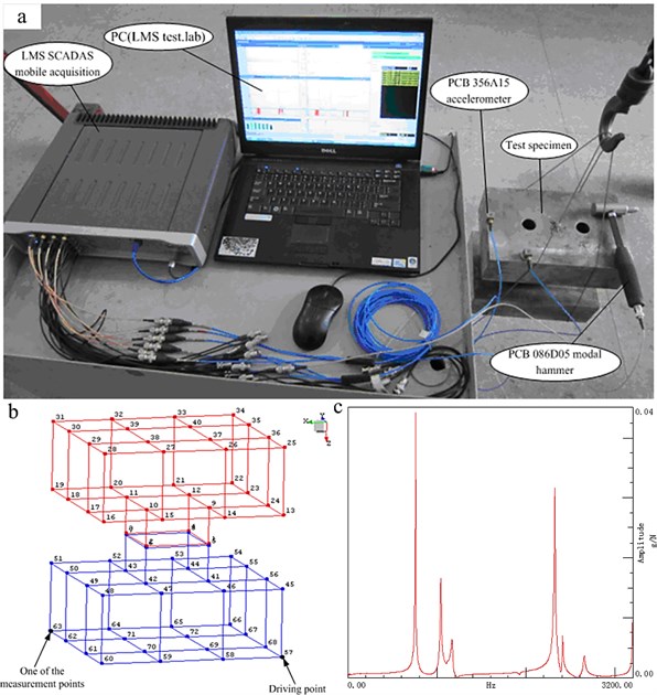
Table 2Experimental and analytical frequencies of the test specimen
Mode shape | Modal frequencies (Hz) | |||||
Yawing | Rolling | Pitching | Left-right translation | Front-back translation | Up-down translation | |
Experimental results | 748.4 | 1027.3 | 1150.4 | 2305.2 | 2385.2 | 2622.3 |
Analytical results | 733.3 | 926.1 | 1031.6 | 2473 | 2543.2 | 2856.9 |
According to parameter identification method of the stiffness influential factors-based dynamic modeling method, the stiffness matrix of bolted joint contained in the specimen is identified, which is shown in Appendix. The identified stiffness matrix is inserted into the finite element model of the specimen in MSC.PATRAN. The analytical modal data of the whole specimen are obtained. The comparison of experimental and analytical modal frequencies is shown in Table 2. It indicates the identified stiffness matrix represents the contact stiffness of the bolted joint accurately and reliably. So, the relationship of the stiffness matrices of bolted joint with different material combination represents the relationship of the corresponding contact stiffness.
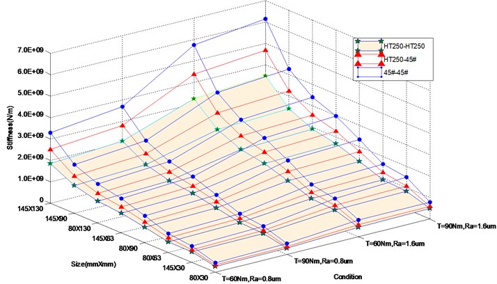
Similar to the process descripted above, the modal test is carried on all the specimens, and the corresponding stiffness matrices are obtained. To increase the number of stiffness matrix, the roughness of bolted joint ranges two levels of 0.8 µm and 1.6 µm, and the bolted pre-tightening torque ranges two levels of 90 Nm and 60 Nm. Therefore, there are 96 stiffness matrices in total. The first element of these matrices is shown in Fig. 5. It is found that, under the same conditions (including roughness of contact surfaces, pre-tightening force, contact size and so on), relationships of stiffness matrices of bolted joint with the three material combinations can be shown as follows:
where, , and are the stiffness matrices of bolted joints with the material combinations of HT250-HT250, HT250-45# and 45#-45#.
Fig. 5K11 of all stiffness matrices
It is easy to establish the relationship of the corresponding equivalent elastic modulus of the three different material combinations. It is shown as:
where, , and are the corresponding equivalent elastic modulus of the material combinations of HT250-HT250, HT250-45# and 45#-45#.
Comparing Eq. (10) and Eq. (11), it is not difficult to find that the ratios of the stiffness matrices of bolted joints with the material combinations of HT250-HT250, HT250-45# and 45#-45# are equal to the ratios of the corresponding equivalent elastic modulus. It indicates the proportional relationship obtained in Section 2 is reliable. As mentioned above, in application of the stiffness influential factors-based model we proposed, the key is to establish the database of the stiffness matrix. Using the reliable relationship, we do not need to obtain the stiffness matrix of all the three material combinations. Instead, it just needs to obtain the stiffness matrices of bolted joint with one material combination under different conditions and the two others is obtained by the proportional relationship. It provides a great convenience to the wide application of the stiffness influential factors-based dynamic model.
4. Application of the proportional relationship
4.1. The beam-rail bolted connected long beam
According to the connection between beam and rail in the MC2000 Plano Machining center, we designed and manufactured a beam-rail bolted connected long beam. The long beam is made of two identical sub-structures, as shown in Fig. 6. The size of the sub-structure is 1505 mm×63 mm×58 mm, and the material of the two sub-structures is 45#. The two sub-structures are connected by 20 M16 bolts, and the distance between every two adjacent bolts is 75 mm. The pre-tightening torque of every bolted is 90 Nm, and the roughness of the contact surfaces is 1.6 µm. After an impact modal test is carried on the structure under free-free boundary condition, the experimental modal frequencies and are obtained.
Fig. 6Geometrical model of the beam-rail bolted connected long beam
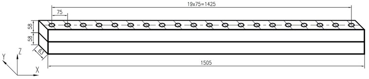
The analytical model is established using FEM. The interface between every two adjacent bolts is simplified as a connection finite element resulting in 19 elements in total. The contact size of all the element is 63×75. Under the condition of 1.6 µm and 90 Nm, , and are obtained using the method descripted in Section 3. The stiffness matrix of the bolted joint is obtained using three means: i) ; ii) ; iii) . Therefore, three analytical results are acquired. The comparison of the experimental modal frequencies and the analytical ones is shown in Table 3. It shows that the first four modal frequencies of the three analytical results are almost identical and agree with the experimental modal frequencies with minor errors.
Table 3Modal frequencies of the beam-rail bolted connected long beam
Mode shape | Experimental results | Analytical results | |||
(Hz) | first-order bending | 148 | 147.3 | 147.3 | 147.3 |
(Hz) | first-order bending | 243 | 257.73 | 257.97 | 257.2 |
(Hz) | second-order bending | 402 | 401.37 | 401.37 | 401.37 |
(Hz) | third-order bending | 774 | 774.29 | 774.3 | 774.28 |
4.2. The bed-column bolted connected block structure
The column is connected to the bed by 11 M24 bolts in XHK5140 automatic tool-changing CNC vertical boring and milling machine tools. According to the connection, a bed-column bolted connected block structure is prepared, as shown in Fig. 7. The two identical sub-structures are connected together by 11 M24 bolts, and the material of the two sub-structures is HT250. The pre-tightening torque of every bolted is 90 Nm, and the roughness of the contact surfaces is 1.6 µm. After the impact modal test is carried on the structure, the experimental modal frequencies are obtained.
Fig. 7The dimension of bed-column bolted connected block structure
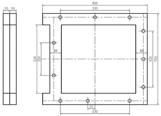
The analytical modal frequencies and mode shapes are obtained by FEM. The joint between every two adjacent bolts is considered as a connection finite element. The stiffness matrices of the connection finite elements are obtained in three means: i) ii) iii) . The same with the example above, there are three analytical modal frequencies and mode shapes, as listed in Table 4 and Table 5, respectively. As shown in the table, there are almost no deviations among the three analytical results and all of the three results match the experimental results with slight errors.
Table 4Modal frequencies of the bed-column bolted connected block structure
Experimental results | Analytical results | |||
(Hz) | 172.636 | 158.04 | 160.26 | 157.56 |
(Hz) | 252.529 | 255.67 | 255.69 | 255.67 |
(Hz) | 403.061 | 409.07 | 409.08 | 409.08 |
(Hz) | 611.324 | 601.28 | 606.55 | 600.76 |
5. Conclusions
The stiffness influential factors-based modeling method we proposed has been proved to provide an effective and accurate dynamic model of bolted joint in machine tools. According to the method, the bolted joint is considered as a connection finite element and the contact stiffness is expressed as a stiffness matrix with 24×24 dimension. The key of wide application of the method is the establishment of the database of stiffness matrices of bolted joint under different conditions. This study presents a reliable proportional relationship of the stiffness matrices of bolted joint with different material combinations. Based on Hertz contact theory, the deduction shows the contact stiffness of bolted joint with different material combination is proportional to the corresponding equivalent modulus. According to the stiffness influential factors-based modeling method, a series of specimens with different contact size, material, roughness and pre-tightening torque are manufactured. After the impact modal test and parameter identification, the stiffness matrices of bolted joints with the material combinations of HT250-HT250, HT250-45# and 45#-45# are obtained. It is not difficult to find the ratios of stiffness matrices of the three material combinations are equal to the ratios of the corresponding equivalent modulus. It indicates the relationship of contact stiffness of bolted joint with different material combination developed in this paper is reliable. Finally, the model of the beam-rail bolted connected long beam and the bed-column bolted connected block structure are presented to show application of the proportional relationship. The reliable relationship of stiffness matrices of bolted joint with different material combination can reduce the size of stiffness matrix database significantly and provide a great convenience to the application of the stiffness influential factors-based modeling method of bolted joint in machine tools. However, it is well-known that there are many isotropic materials used in machine tools except the two materials studied in this study, the proportional relationship is worth to validate on the bolted joint with other different material combinations.
Table 5Mode shapes of the bed-column bolted connected block structure
Order | Experimental mode shapes | Analytical mode shapes | ||
1 | 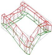 | 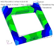 | 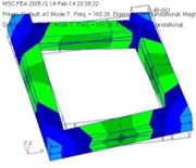 | 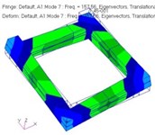 |
2 | 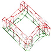 | 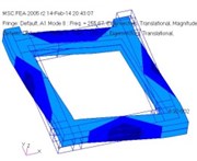 | 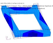 | 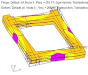 |
3 | 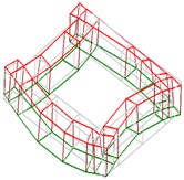 | 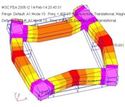 | 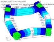 | 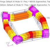 |
4 | 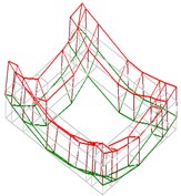 | 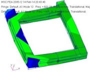 | 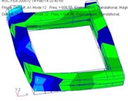 | 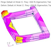 |
References
-
Oskouei R. H., Keikhosravy M., Soutis C. A finite element stress analysis of aircraft bolted joints loaded in tension. The Aeronautical Journal, Vol. 114, 2010, p. 315-320.
-
Camanho P. P., Fink A., Obst A., Pimenta S. Hybrid titanium-CFRP laminates for high-performance bolted joints. Composite Part A – Apply Science Manufacture, Vol. 40, Issue 12, 2009, p. 1826-1837.
-
McCarthy M. A., McCarthy C. T., Lawlor V. P., Stanley W. F. Three-dimensional finite element analysis of single-bolt, single-lap composite bolted joints: Part I – model development and vibration. Composite Structures, Vol. 71, Issue 2, 2005, p. 140-158.
-
McCarthy C. T., McCarthy M. A. Three-dimensional finite element analysis of single-bolt, single-lap composite bolted joints: Part II – effects of bolt-hole clearance. Composite Structures, Vol. 71, Issue 2, 2005, p. 159-175.
-
Fukuoka T., Nomura M. Proposition of helical thread modeling with accurate geometry and finite element analysis. Journal of Pressure Vessel Technology, Vol. 130, 2008, p. 011204-1-011204-6.
-
Abad J., Franco J. M., Celorrio R., Lezaun L. Design of experiments and energy dissipation analysis for a contact mechanics 3D model of frictional bolted joints. Advances in Engineering Software, Vol. 45, 2012, p. 42-53.
-
Kim J., Yoon J. C., Kang B. S. Finite element analysis and modeling of structure with bolted joints. Applied Mathematical Modelling, Vol. 31, 2007, p. 895-911.
-
Wang R., Corcombe A. D., Richardson G., Underwood C. I. Energy dissipation in spacecraft structures incorporating bolted joints operating in macro-slip. Journal of Aerospace Engineering, Vol. 21, 2008, p. 19-26.
-
Ahmadian H., Jalali H. Identifiaction of bolted lap joints parameters in assembled structures. Mechanical System and Signal Processing, Vol. 21, 2007, p. 1041-1050.
-
Kspidzic Z., Nilsson L., Ansell H. Finite element modeling of mechanically fastened composite-aluminum joints in aircraft structures. Composite Structures, Vol. 109, 2014, p. 198-210.
-
Gray P. J., McCarthy C. T. A global bolted joint model for finite element analysis of load distributions in multi-bolt composite joints. Composites, Part B, Vol. 41, 2010, p. 317-325.
-
McCarthy M. A., McCarthy C. T., Padhi G. S. A simple method for determining the effects ofbolt-hole clearance on load distribution in single-column multi-bolt composite joints. Composite Structures, Vol. 73, 2006, p. 78-87.
-
McCarthy C. T., Gray P. J. An analytical model for the prediction of load distribution in highly torqued multi-bolt composite joint. Composite Structures, Vol. 93, 2011, p. 287-298.
-
Iranzad M., Ahmadian H. Identification of nonlinear bolted lap joint models. Computre and Structures, Vol. 96-97, 2012, p. 1-8.
-
Tian Hongliang, Li Bin, Liu Hongqi, Kuanmin Mao, Fangyu Peng, Xiaolei Huang A new method of virtual material hypothesis-based dynamic modeling on bolted joint interface in machine tools. Journal of Machine Tools and Manufacture, Vol. 51, Issue 3, 2011, p. 239-249.
-
Greenwood J. A., Williamson J. P. B. Contact of nominally flat surfaces. Proceedings of the Royal Society of London, Series a-Mathematical and Physical Sciences, Vol. 295, Issue 1442, 1966, p. 300-319.
-
Yoshimura M., Okushima K. Measurement of dynamic rigidity and damping property for simplified joint models and computer simulation. Annals of the CIRP, Vol. 25, 1977, p. 193-198.
-
Yoshimura M. Computer-aided design improvement of machine tool structure incorporating joint dynamics data. Annals of the CIRP, Vol. 28, Issue 1, 1979, p. 241-246.
-
Wang Shijun, Huang Yumei, Zhao Jinjuan, Zhang Guangpeng, Wang Kai Finite element analysis for machine tools. China Mechanical Engineering, Vol. 15, Issue 18, 2004, p. 1634-1636, (in Chinese).
-
Kuanmin Mao, Bin Li, Jun Wu, Xinyu Shao Stiffness influential factors-based dynamic modeling and its parameter identification method of bolted joint in machine tools. International Journal of Machine Tools & Manufacture, Vol. 50, Issue 2, 2010, p. 156-164.
-
Dohner J. L., Gregory D. L., Segalman D., Martinez D. R. On the development of methodolodies for constructing predictive models of structures with joints and interfaces. US Department of Energy, White Paper, Sandia National Laboratories, 2001.
-
Salih N. H., Patil M. J. Hybrid (bonded/bolted) composite single-lap joint and its load transfer analysis. International Journal of Advanced Engineering Technology, Vol. 3, Issue 1, 2012, p. 213-216.
-
Kahshab U. A., Sallam H. E. M., Al-Shorbagy A. E., Seif M. A. Effect of washer size and tightening torque on the performance of bolted joints in composite strucutres. Composite Structures, Vol. 73, 2006, p. 310-317.
-
Ekh J., Schon J. Finite element modeling and optimization of load transfer in multi-fastener joints using structural elements. Composite Structures, Vol. 82, 2008, p. 245-256.
-
Huang Y. M., Fu W. P., Dong L. X. Research on the dynamic normal characteristic parameters of joint surface. Chinese Journal of Mechanical Engineering, Vol. 29, Issue 3, 1993, p. 74-78, (in Chinese).
-
Xiaocong He Influence of sheet material characteristics on the torsional free vibration of single lap-jointed cantilevered spr joint. International Conference on Measuring Technology and Mechatronics Automation, 2009, p. 800-803.
-
Xiaocong He Sheet material property effects upon dynamic behavior in self-pierce riveted joint. Materials Science Forum, Vol. 675-677, 2011, p. 999-1002.
-
Shinji Shimizu, Kyoko Nakamura, Haruhisa Sakamoto Quantitative measurement method of contact stiffness of the joint with different material combination. Journal of Advanced Mechanical Design, Systems, and Manufacturing, Vol. 4, Issue 5, 2010, p. 1044-1053.
-
Jhonson K. L. Contact Mechanics. Cambridge, Cambridge University Press, 1985.
-
Shao Wang Real contact area of fractal-regular surfaces and its implications in the law of friction. Journal of Tribology, Vol. 126, Issue 1, 2004, p. 1-8.
-
Tian Hongliang Dynamic modeling on fixed joint interface virtual material in mechanical structure. Doctoral Dissertation, Huazhong University of Science and Technology, 2011, (in Chinese).
About this article

This work was supported by Key Projects in the National Science and Technology Pillar Program (No. 2012BAF08B01). The authors are grateful to other participants of the projects for their cooperation.
