Abstract
Two-dimensional linearized Navier-Stokes equations have been used to model the inviscid fluid forces acting on a vertical rotor-cylindrical stator system partially immersed in an inviscid incompressible fluid. The response of the fluid-stator-system subjected to subsequent fault feature extraction. The influences of parameters of the fluid system, among them, fluid density, and mass ratio on the unstable contact zones are analyzed. It is shown that for an effective prediction of rub-impact in a submerged rotor system, the influence of the fluid mass on the stability of the system is an important dynamic factor. It is revealed, that the fluid forces increase the amplitude of vibration, while the frequency of oscillation is reduced, phenomena that stabilise the isotropic vertical rotor-stator system.
Highlights
- Two-dimensional linearized Navier-Stokes equations have been used to model the inviscid fluid forces.
- The response of the faulted fluid-rotor-stator system has been extracted through Time-Frequency analysis.
- Vibration response indicates the higher frequency amplitude, irregularity in orbit orientation and conspicuous deflection.
- The analysis revealed that the fluid forces reduce the frequency of the rubbing fault.
- STFT and NWSST show effectiveness on distinguishing features of unbalance and rub fault.
1. Introduction
From the engineering perspective, Fluid-Structure Interaction has major importance when taking into account the response of the fluid on structures for safety, reliability and life issues concerning the efficiency of rotating systems. The motion of the structure modifies the flow conditions at the interface with the fluid, and the fluid perturbation subsequently affects the mechanical integrity of the vibrating structures. Kadyrov et al. studied the vibration behaviour of a rigid cylinder in a cylindrical duct filled with a compressible viscous fluid [1]. They presented approximated results for the frequency subjected to various parameters of the fluid. Kydyrbekuly et al. investigated the dynamic model of the fundamental rotor-fluid considering the nonlinear stiffness coefficient of the bearings, together with the vibrations of fluid and the foundations [2]. The obtained results allow optimizing the parameters of the rotor, fluid and foundation, which minimizes the stresses throughout the contact surfaces. Tchomeni and Alugongo studied the oscillations of a faulted horizontal rigid rotor in a viscous fluid under the parametric excitation. The study demonstrated that the viscous fluid forces are the source of unwanted frequencies that initiates and expand the features of the crack along with the rotor lateral deflection shapes [3].
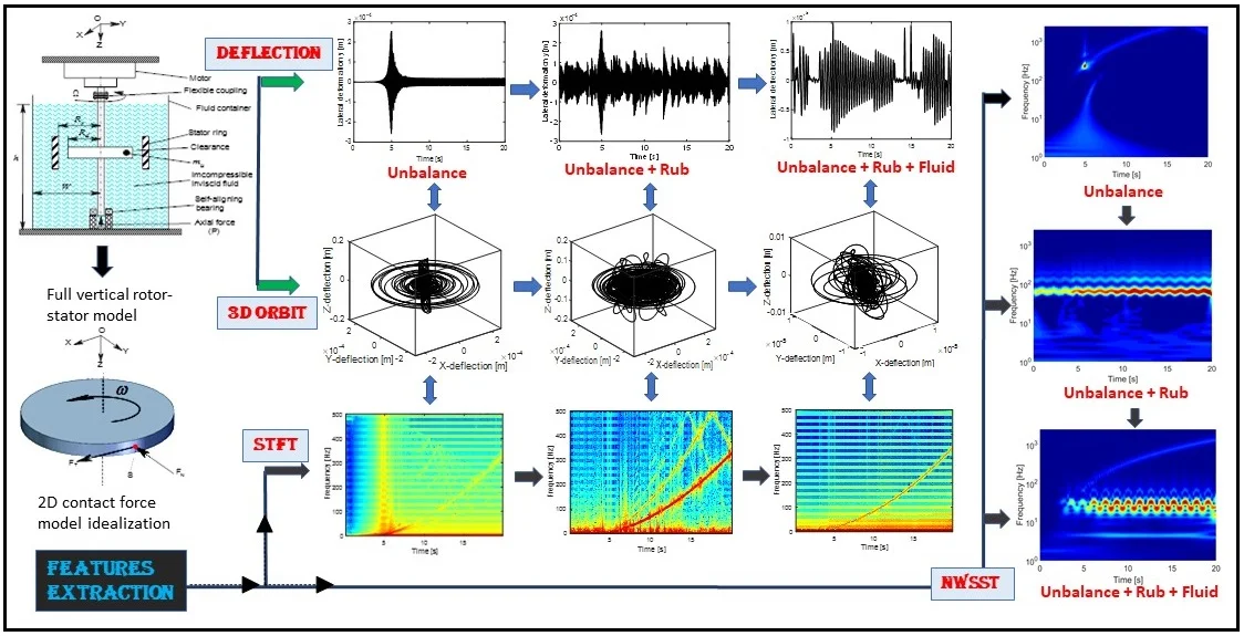
The current paper extends the investigations in [3] by considering the rotor-stator impact. An effort is made to establish a mathematical model for analysing vibration of an unbalanced vertical rotor-stator rub system partially submerged in an inviscid fluid. The isotropic rotor system comprises an elastic coupled lateral-torsional and axial vibration shaft. Linearized Navier-Stokes equations are concisely adopted to estimate the hydrodynamic perturbation acting on the vertical rotor. Parametric excitation forces representing the rub-impact is introduced as a perturbation at the contact point. For effective features extraction of some hidden rub features, the obtained highly nonlinear model has been studied based on the Time-Frequency techniques namely, Short Time Fourier Transform (STFT) and improved Nonlinear Wavelet Synchrosqueezed Transform (NWSST).
1.1. Vertical rotor system description and governing equations
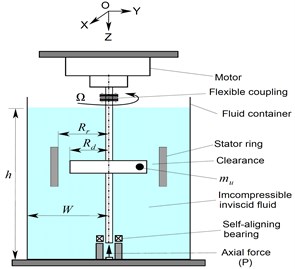
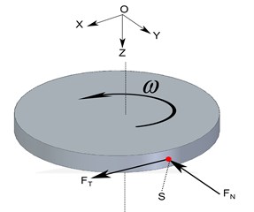
The proposed model of the coupling between lateral and torsional vibrations of the isotropic vertical rotor is found quite often in literature as a horizontal rotor [3, 5]. In this work, the model of vertical Jeffcott rotor of lumped-disc-shaft submerged in an inviscid incompressible fluid is presented for fault analysis, as shown in Fig. 1(a).
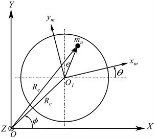
Fig. 1(a) is an illustration of the schematic diagram of elastic rotor-stator model partially immersed in an incompressible inviscid fluid medium, taking into account the effect of an axial force. The governing equations of the fully coupled rotor lateral-torsional vibrations are determined under various assumptions and based on the factor such as unbalance as formulated in [3], with consideration of the rotor-stator rub and axial force effects. The obtained nonstationary 4-Degree of Freedom (DOF) responses consists of two orthogonal bending deflections of the shaft-disc of fixed coordinate centre , one axial displacement along -axis with axial forceand finally one vertical shaft rotation . The general coordinates applied to derive the system equations are displayed in Fig. 1(b), where is the inertial coordinate frame; is associated with the motor gearbox system. The unbalance mass, , is located by the eccentricity distance from the reference linked to the rotating disc .
Fig. 1a) Full vertical rotor-stator model, b) rotor deformation in fixed coordinate
a)
b)
1.2. Energy principle expression
Based on the geometry and rotor deformation shown in Fig. 1(b), and considering the modal damping, the kinetic dissipative energy of the motor-disc-shaft system is written as:
where represents the mass moment of inertia of the motor, is the mass of the rotor, is the disc mass moment of inertia and is the mass unbalance.
1.3. Expression of potential energy
The expression of the potential energy of the rotor system comprises the lateral shaft deflection, shaft strain energy and is given by:
where , , are the laterals shaft stiffness and is the axial stiffness coefficients associated with the system DOF. A rotor’s high-speed level generates axial vibration in the bottom of the vertical rotor, which excessively creates an axial force that influences the rotor stiffness as shown in [6] and expressed as follows:
where , , and respectively are, the shaft’s length, the initial stiffness for first mode deflection and the rotor axial compressive force. In this study, , which is assumed to fluctuate harmonically about a constant mean value is written as:
where , and are amplitudes and shaft rotational angle respectively. Considering the effect of the viscous modal damping coefficient, the total dissipated energy of the system can be expressed as:
where, , and are the respective laterals and axial damping coefficient.
1.4. Mathematical expression of rub-contact
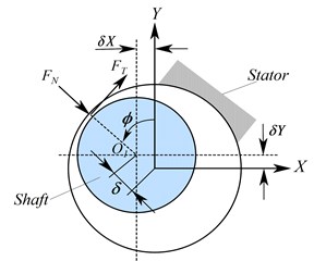
Upon applying the method in [5], into Fig. 2, the geometrical location of the shaft centre and the contact forces between the rotor and stator in the Cartesian coordinate frame are:
where, and are stator radial stiffness and coefficient of dry friction, respectively.
Fig. 2a) Schematic of the contact system, b) 2D contact force model idealization
a)
b)
1.5. Hydrodynamic excitation force expressions
In this section, the hydrodynamic forces expressions coupled with the oscillating vertical rotor under lateral excitation are established. The equations of fluid motion can be found with more details in [3] and will not be repeated herein. Considering the basic mechanism of the filled rectangular tank, the lateral vibration of the vertical shaft modifies the stream flow at the interface with the fluid which is subjected to sinusoidal excitation displacement along -direction expressed as:
where, , are the excitation amplitude, and is a cyclical frequency in cycles per unit of time much lower than its fundamental frequency (). In the assumption that the disc has approximately the same radius with the shaft (), the hydrostatic pressure () is neglected. Considering the total velocity potential function , the hydrodynamic pressure interfacing at any point along with the rotor is determined by the pressure Eq. (8):
where . The acting force along the -axis can systematically be obtained by resolving the hydrodynamic pressure at the first mode 1 and as shown in [3]:
where the overall mass of the fluid is defined by and . The force acting on the bottom of the container and along the -axis are nil:
The pressure is symmetrically distributed at -direction along the tank wall to cancel the integration over it. The fluid force acting on the shaft can then be differentially simplified to:
For incompressible inviscid fluid flow, the obtained extra fluid mass is added and coupled into the inertial force of the shaft as [3]:
1.6. The general equations of motion
The Lagrangian equation of a system in generalized coordinate frame is:
Upon substitution of Eqs. (1), (2), (5), (6) and (11) into Eq. (13), performing the requisite differentiation and algebraic manipulation, the final rotor system expression obtained in a matrix form reads:
where the first element of Eq. (17) represents the inertia rotor mass matrix, which displays coupling between different generalized coordinate of the rotor system [5]. represents the nonlinear terms of Coriolis components and the vector component of the external forces associated with the with each DOF. The damping ratio and natural frequency of the first asymmetric mode of a cylindrical rotor are 1.841 and , where is the container width, is the acceleration due to gravity [3].
2. Numerical simulation results and discussions
Based on Eq. (17), the dynamic responses of vertical rotor system submerged in the fluid domain are evaluated through the Runge-Kutta method with adaptive integration time steps using Time-Frequency Techniques. The physical properties of the rotor and stator system are given in [5]. The responses of the vertical rotor are displayed using the orbit patterns of the shaft centre, the shaft displacement as well as the location of transient phenomena in the Time-Frequency maps near to the first critical speed.
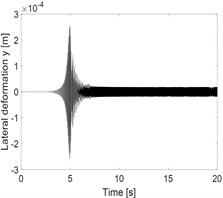
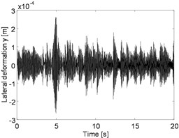
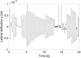
Fig. 3a) Horizontal deflection of the unbalanced rotor, b) horizontal deflection of rubbing rotor and c) horizontal deflection of rubbing shaft in a fluid medium
a)
b)
c)
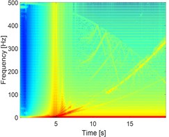
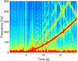
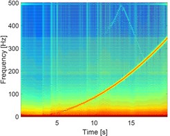
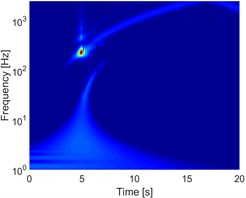
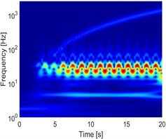
Fig. 4a) STFT of the unbalanced rotor, b) STFT of rubbing rotor and c) STFT of rubbing in a fluid
a)
b)
c)
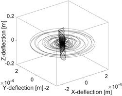
Fig. 5a) Orbit of the unbalanced shaft, b) orbit of rubbing rotor, c) orbit of rubbing in a fluid
a)
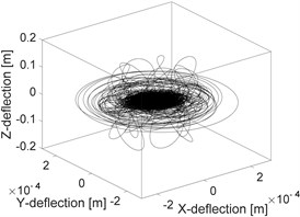
b)
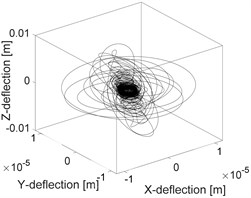
c)
The influence of the fluid on the deflection of the isotropic faulted vertical rotor is observed. Concerning the impact of the friction (coefficients equal to 0.2), a significant change on the deflection of the shaft according to the consideration or not of the dry friction is perceptible. In the analysis of the 3D orbit results, the operating point is stable and more realistic; however, the intensity of the displacements is much more significant in the case of the dry friction compared to the contact in a fluid medium in term of rotor rebounds. The nonlinear behaviour is clearly materialized in STFT maps. However, the configuration changes entirely in a fluid medium, so it is crucial to take into account the friction when analyzing the different energy dissipated during dry friction between the shaft and the stator as observed in NWSST energy plots.
Fig. 6a) NWSST of the unbalanced rotor, b) NWSST of rubbing rotor and c) NWSST of rubbing in a fluid
a)
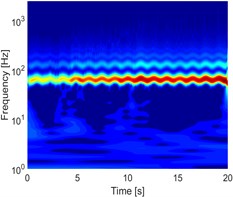
b)
c)
3. Conclusions
Based on extracting the features of rub-impact in an inviscid fluid medium using two-dimensional linearized Navier-Stokes equations, this paper analyses the influences of the inviscid incompressible fluid forces acting on a vertical rotor-stator system by considering the fluid the parameters at the contact regions. It is shown through Time-Frequency analysis that for the isotropic vertical rotor, the inviscid fluid forces may predict two disturbed regions, the first is generally above the critical speed of the empty vertical rotor system, and the other is below the critical speed of the unbalanced rotor system. In the fluid-rotor interaction point of view, adding inviscid fluid forces makes the system more stable with more considerable attenuation of the amplitude of vibration. It may be an effective method to reduce the high contact, but it may as well created unwanted unstable motions around the critical speed.
References
-
Kadyrov S. G., Wauer J., Sorokin S. V. A potential technique in the theory of interaction between a structure and a viscous, compressible fluid. Archive of Applied Mechanics, Vol. 71, Issues 6-7, 2001, p. 405-417.
-
Kydyrbekuly A., Khajiyeva L., Gulama Garyp A.-Y., Kaplunov J. Nonlinear vibrations of a rotor-fluid-foundation system supported by rolling bearings. Strojniski Vestnik/Journal of Mechanical Engineering, Vol. 62, Issue 2016, 6, p. 351-362.
-
Tchomeni B. X., Alugongo A. Modelling and numerical simulation of vibrations induced by mixed faults of a rotor system immersed in an incompressible viscous fluid. Advances in Mechanical Engineering, 2018, https://doi.org/10.1177/1687814018819341.
-
Tchomeni B. X., Alugongo A. Numerical and experimental diagnosis of complex rotor system by time-frequency techniques. MATEC Web of Conferences, Vol. 169, 2018, p. 01015.
-
Al-Bedoor B.-O. Transient torsional and lateral vibrations of unbalanced rotors with rotor-to-stator rubbing. Journal of Sound and Vibration, Vol. 229, Issue 3, 2000, p. 627-645.
-
Yigit A. S., Christoforou A. P. Coupled torsional and bending vibrations of actively controlled drillstrings. Journal of Sound and Vibration, Vol. 234, Issue 1, 2000, p. 67-83.
About this article

The authors would like to express the gratitude to the Vaal University of Technology at the Department of Mechanical Engineering (South Africa).
