Abstract
In this paper we employed the Fast ICA Independent Component Analysis algorithm for decomposing vibration data in operational Stirling engine. Accurate separating vibration signals containing noises allows for the early fault detection of the Stirling engine and by this guarantees the more reliable work of this engine and its better performance. The results show that using the Fast ICA blind source separation algorithm enhances the quality of obtained fault detection information, which is more precise and makes the fault diagnosis more effective.
1. Introduction
A Stirling engine is an external combustion engine based on the Stirling Cycle. Developed first in 1816 by Robert Stirling, this engine produces power from differences in temperature. The working fluid inside the engine, typically air, hydrogen or helium, is heated on the one end and cooled on the other, consequently causing the gas to expand and compress, respectively. In addition, the expansion and compression of the working fluid move two pistons within the engine cylinder, which in turn are depending on the configuration, coupled in some manner with a drive mechanism to produce a net power output [1, 2]. The Stirling engine requires a sufficient temperature difference (-) to operate. The effective maintenance needs to anticipate faults of the Stirling engine. One of the important factor to observe during the various loads of this engine is a vibration. A drive mechanism poses some problems for the Alfa type Stirling engine, since discontinuous motion is required to achieve the volumetric changes that result in a net power output. For this reason, in this engine for transferring dual piston motion into rotational motion – the Ross yoke mechanism has been implemented (Fig. 1).
Fig. 1The Stirling engine plant facilities
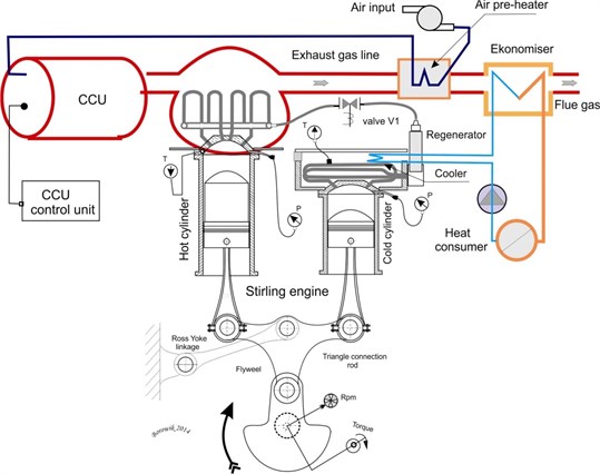
The absence of explosive nature in converting heat energy into mechanical one, conveys to silent and cleaner operation. The power output is produced by the separate motions of the individual pistons. Piston coupling is very important in Stirling engines. There are three basic forms with many further subdivisions. A rigidly coupled Stirling engine uses a solid mechanical linkage that connects the reciprocating elements to each other and the power take-off mechanism. Typical types of rigid coupling include: slider-crank, rhombic drive, swash plate, Scotch Yoke, crank-rocker, and Ross rocker. In tested model was adopted the Ross yoke linkage. The radiated noise of Stirling engine is mainly produced by the pistons and Ross yoke.
The measured vibration signal on the shell of the Stirling engine is the mixed signal affected by many sources. Measuring and analyzing the Stirling engine vibration signal is a complicated and difficult process. This vibration signal is influenced by many different sources, for example is caused by a pressure relief and the Stirling engine other mechanism operations. It is very important to separate the different sources from the measured vibration signal of the Stirling engine and its cylinders.
2. The Fast ICA algorithm
Fast ICA (Fast Independent Component Analysis) is a method often used to solve Blind Source Separation problems (BSS). Those problems are widespread in many different areas of life. Recently, BSS algorithms are also often applied to complex data. Due to the continuous process of appearing many enhancements in technologies, the complexity of the available data is also increasing. And new statistical methods need to deal with more complex, massive and high-dimensional data, which often contain redundant information. BSS problem is commonly used by many approaches. One of the most popular is Principal Component Analysis (PCA), which is a model free method [3].
Lack of assumptions in PCA sometimes may cause that the obtained solution cannot be interpretable. In the group of methods that make assumptions on the sources the most common is Independent Component Analysis (ICA) method. There are also very many other groups, like Wavelets, Treelets and the group of methods that aim to search for the interpretable solution by imposing some kind of constraints on source matrix and/or mixing (basis) matrix in the estimate procedure and those constraints usually come from some a’priori knowledge on the source matrix and the basis matrix.
Shortly we may say that in a BSS problem we try to estimate the mixing matrix and the source matrix, while having the data matrix with observations.
2.1. Assumptions of fast independent component analysis method
Let the data matrix be a linear combination of independent (non-Gaussian) components, such that the observation matrix , , where the matrix is a scalar linear mixing matrix (and the source matrix contains independent columns, source components). is the matrix with certain additive Gaussian noise. Usually the goal of ICA is to estimate the mixing matrix and/or the source matrix , given only the observation matrix .
Blind identification of the mixing matrix is possible only if certain assumptions about the source vectors have been made. The most often used assumption is that the source vectors are mutually statistically independent (what implies a diagonal covariance and higher-order cumulants), and independent from the noise components [5].
In our case the Fast ICA method tries to “un-mix” the data to obtain the matrix and it tries to search for (to estimate) an un-mixing matrix , such that , and which maximizes the non-gaussianity of the source independent columns of the matrix . (In this work, we restrict ourselves to the overdetermined case, when . In the opposite case, i.e. in the underdetermined ICA problem – there are more vibration signal sources than sensors).
The measured signals in matrix are usually ‘more Gaussian’ than the columns of the matrix (this could be explained by the Central Limit Theorem).
The dimensions of these matrices are pre-determined by the following values: the dimension is the number of sensors, the dimension is the number of vibration signal sources, and the dimension is the number of samples in each observation.
In this paper we applied the Fast ICA method, in which non-gaussianity is calculated by approximating neg-entropy (), as this way is more robust than calculations done with the use of kurtosis. The neg-entropy approximation has the following form:
where is Gaussian random variable, with 0-mean and unit-variance. Function is a nonlinear, non-quadratic function, most commonly it is a logarithmic one or an exponential one .
The Fast ICA method based on neg-entropy has some advantages, such as fast computing speed, good stability and clarity of the algorithm [3].
Concerning the algorithm itself, first, the data are centered by subtracting the mean of each column of the data matrix . Then the data matrix is then ‘whitened’ by projecting its data onto its principal component directions (i.e. , where is a pre-whitening matrix).
The Fast ICA algorithm then tries to estimate a matrix , such that .
The algorithm chooses such a matrix , which maximizes the neg-entropy approximation under the constraints that this matrix is an orthonormal matrix, what allows to ensure that the estimated components are uncorrelated. The algorithm is based on a fixed-point iteration scheme for maximizing the neg-entropy.
3. Source separation of the Stirling engine signals based on the Fast ICA method
We have investigated only one function of a remote Sensor Network: a vibration. (However, the digital accelerometer has many sensing possibilities, and it is capable to recognize numerous functions, such as motion, vibration, freefall, shock and tilt).
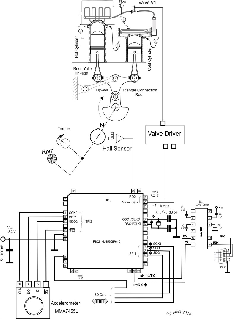
16-bit microcontroller PIC24H with 124 kB of program memory has been chosen, having on-board two SPI and two I2C modules. It has capability of programming with JTAG as well as with ICSP (InCircuit Serial Programming). ICSP jack is depicted in the top of the diagram as the 6-pin J12 jack. The circuit operates with the Q1 oscillator with the frequency of 4 MHz. Also USART is provided working with MAX232. Accelerometer IC3 is connected via SPI2 to the circuit as shown in Fig. 2.
As the influence of structural transmission, some components of vibration sources will be changed as they go through mechanical structures, what means the measured vibration signals on the Ross Yoke, shaft pistons and all dynamic structures of the Stirling engine will be influenced by each other. As the result the measured signal is the mixed signal of all these sources in the Stirling engine during its normal operation. The reduction and control of vibrations and noises – is an important work which improves the operational performance of the Stirling engine and its survival capabilities.
One of the simplest way to reduce the radiated noise is based on improving the hull structure to reduce a vibration transmission. Measuring a vibration signal plays an important role in the troubleshooting of the Stirling engine. When the rotational parts, such as rolling bearings, rings of the pistons are malfunctioning, the vibration signals are measured on the carter of the Stirling engine. The source signals of the malfunctioned components cannot be well revealed just by the measuring these signals. As the composite faults occur, the vibration signals will be coupled together, and thus it is difficult to reveal the condition of every single part. Therefore, some vibration signals of typical fault features are selected to test the separating capability and performance of some particular methods (like fast ICA). The vibration responses of the linear time-varying structure are frequency and amplitude modulated signals. Four source signals are selected: is a white noise signal, is a frequency modulated signal, is an amplitude modulated signal, and is a both, amplitude and frequency modulated signal.
Fig. 2Accelerometer sensor connected via SPI protocol to the microcontroller
Acceleration sensors are used to sample the vibration signals. Three sensors are installed on the carter of the Stirling engine to measure the mixed signals. During the testing, the sampling frequency was equal to 16384 Hz, the data length of was set to 100, the step was 1, and the unit of measured signals was set to g (1.0 g 9.8 m/s2).
Fig. 3Waveforms of the S2 and S4 source signals
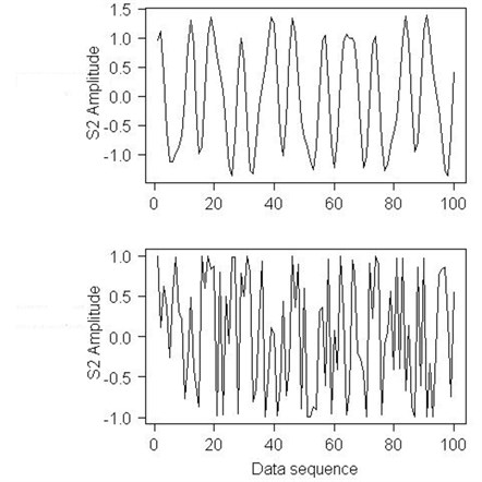
Fig. 4Waveforms of the S2 and S4 mixed signals
The Stirling engine has been tested at 3 rotational speeds: 230 rpm, 350 rpm, 470 rpm (for frequency 3.83 Hz, 5.83 Hz and 7.83 Hz).
Aiming at the active control over vibration and noise in the Stirling engine, a novel approach based on the Independent Component Analysis (ICA) method is proposed in this paper, which identifies the vibration sources from the mixed signals, and quantitatively evaluates the source contributions.
Firstly, the vibration signals at the different positions of the Stirling engine are measured, and the radiated noise is evaluated according to the signal energy. Secondly the signals which radiate the noise significantly are selected as the mixed signals, and the source signals contained in the mixed signals are extracted by the Fast ICA method. Thirdly, the vibration signals on the engine bases are measured as the source signals, and the vibration sources are identified according to correlation analysis. Lastly, the contributions of each source are quantitatively calculated according to the mixing mode of the independent components. Therefore, the vibration sources which have big contributions can be online identified and controlled if necessary, which provides a novel approach for active control over the vibration and noise.
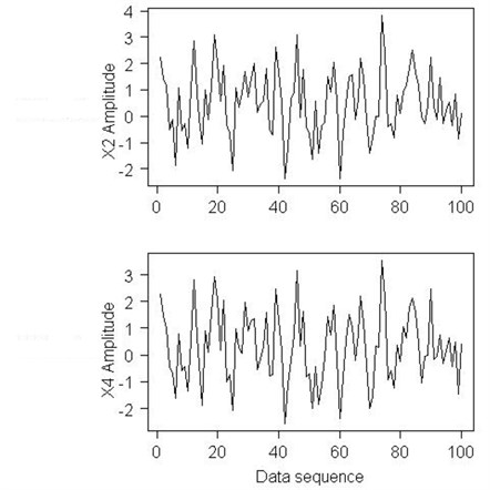
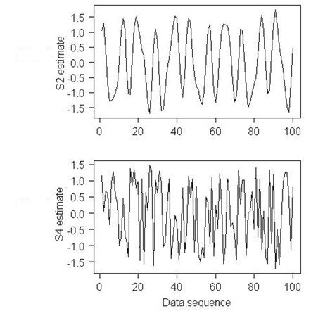
Fig. 5The Fast ICA method estimates of the S2 and S4 signals
4. Conclusions
The Fast ICA Independent Component Analysis algorithm that we have used in this paper for decomposing vibration data in operational Stirling engine has allowed for accurate separating vibration signals containing noises, what has helped in early fault detection of the Stirling engine and has increased the Stirling engine reliability and its better performance. The results obtained from the Fast ICA blind source separation algorithm executed in the R programming environment has enhanced the quality of the obtained fault detection information, which has been more accurate and which allows for more correct decisions to be made and the whole fault detection process to be more effective.
References
-
Graham W. Stirling Engines. Oxford University Press, Oxford, 2000.
-
Organ A. J. The air engine: Stirling cycle power for a sustainable future, Woodhead Publishing Limited. Abington, Cambridge, 2007.
-
Marchini J. L., Heaton C., Ripley B. D. FastICA, R programming platform package, available from: http://cran.r-project.org/web/packages/fastICA.
-
Borowik B., Kurytnik I.P. PIC Microcontrollers in Applications. PAK Publ., 2009, (in Polish).
-
Hyvarinen A., Karhunen J., Oja E. Independent Component Analysis. Wiley, New York, 2001.
About this article

