Abstract
The problem of stabilization resonant oscillation of mechanical system excited by unbalanced rotor of an asynchronous AC motor is considered. An algorithm for automatic adjustment of the vibrational technological machine to the resonant regime at changing process loads and/or supply voltage is proposed.
1. Introduction
The actual problem of designing high performance vibration machines is stabilization its resonant operating regime. Using resonant modes allows to reduce power consumption and to increase machines performance [1].
However, in a range of cases, the problem of resonant tuning is due to not only changing of operating loads and nonlinear mechanical characteristics, but also the dynamic interaction of the machine and vibratory drive. Here the Sommerfeld effect is primarily meant [1-3]. This is the reason why the most of vibration machines operates in below-resonance regime or after-resonance regime.
The issue of stabilization of the resonant regime of the unbalanced exciter with DC motor by using feedback into the angular velocity control system is well-developed [1, 4].
However, the issue of stabilization of the resonant regime of the systems driven by an asynchronous motor (the most widely used in vibration machines) so far is poorly understood and requires further development.
In the present paper we consider the automatic adjustment to the resonant regime of the vibration machine with unbalanced exciter and asynchronous AC motor at fluctuations of operating loads.
2. Design scheme and equations of motion
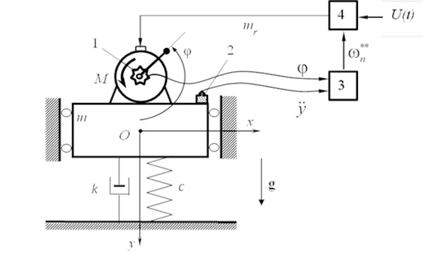
The scheme is shown in Fig. 1. It allows to identify and describe the most important dynamic properties of different real machines [1-5]. A platform with operating loads is represented in the form of a rigid body with a mass . Visco-elastic support has linear characteristics: stiffness and damping coefficient . The platform can oscillate only in vertical direction. Unbalanced exciter driven by an asynchronous three-phase AC motor is installed on the platform. The exciter has unbalanced mass and eccentricity .
In contrast to the commonly used description of the drive torque as a function of the angular velocity of rotation (static characteristics of the engine), this study examines the relationship between flux linkages and currents for all phases of the stator and rotor. It allows us to describe the control system. We also take into account the constant resistance torque of the motor .
Motion of the system is considered in the fixed in space coordinate system . Its origin is aligned with the position of the common center of mass, and the vertical axis coincides with the direction of gravity . Angle of rotation of the rotor is described by , counterclockwise from the positive direction of the axis .
Fig. 1Design scheme
The equations of motion of the system are of the form [2-5]:
where is the reduced moment of inertia of the unbalanced rotor; dots denote the total derivative with respect to time .
Electromagnetic torque is written in the form [5, 6]:
Here, as in [5] the following designations are used: and – flux and currents in the respective phases of the stator winding, the subscript 1 denotes variables relating to the phases , , of the stator, the subscript 2 denotes variables relating to phases , , of the rotor; is the number of poles of the motor.
The connection between the flux linkages and currents is set from equilibrium conditions of voltage for all phases of the stator and rotor [5, 6]:
where:
wherein and – resistance in the stator and the rotor windings; – the column vectors of the instantaneous values of voltage, current and flux linkage of the stator and the rotor, and is amplitude of the voltage; is frequency of the AC; – zero column vector (zero voltage on all phases of the rotor).
Matrices of inductance , characterize the relationship between the currents and flux linkages of phases of the stator and rotor:
where , are complexes formed from motor constants: is the main inductance, are the leakage inductance of the stator and the rotor phases, respectively.
Matrices characterize the interference of currents of the rotor and the stator to the relevant flux linkage:
Thus, Eq. (1)-(3) completely describes the oscillations of the system excited by unbalanced rotor of induction motor. A detailed analysis of the dynamics of the system is given in [5].
3. “Dynamic portrait” of the system
In order to design the control system we consider the dependence of the phase shift between the displacement of the platform and the disturbing force from the natural frequency of the system and the angular frequency of the supply voltage for given other system parameters.
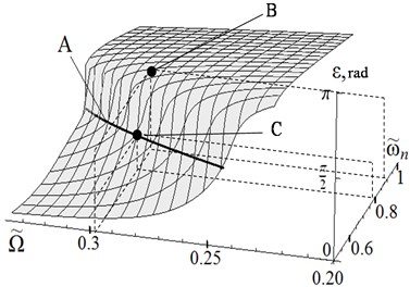
For this purpose, we can use Eq. (1)-(3) to obtain a surface in space . Each point of the surface corresponds to a possible dynamic state of the system.
We call this surface a “dynamic portrait” of the system; it is shown in Fig. 2, where axis , axis , rad/s is a scale factor.
Fig. 2Dynamic portrait of the system
The calculation was performed for the following values of the system parameters: moment of inertia of the rotating parts of the motor with unbalance 0,0032 kg∙m2; stiffness and damping coefficients 444,0 kN/m, and 0,5 kNs/m, respectively; main inductance 1,364 H; leakage inductance of stator phase 0,089 H; leakage inductance of the rotor phase 0,156 H; active resistance of stator phase 56,84 ohms; active resistance of phase of rotor phase 46,23 ohms; the amplitude of the supply voltage 220 V; resistance torque of the rotor 0,02 N∙m; gravity acceleration 9,81 m/s2.
Line A in Fig. 2 shows the resonant state of the system at the phase shift .
4. Resonant regime control
The purpose of the control is automatic adjustment to the resonant regime of the vibration machine at fluctuation of its mechanical or electrical characteristics using a control system with feedback. The control system includes: rotor angle position sensor 1, platform vibration sensor 2, control unit 3, inverter 4 (see Fig. 1). Controlled parameter is the phase shift between the displacement of the platform and the disturbing force, which at resonance must be equal to /2 [1-5]. Since the value of the disturbing force is determined by its projection on the vertical direction (see Fig. 1), then as the measured parameter for this force we can take the angle position of the rotor which can be detected by sensor 1, for example, an encoder. Displacement y and frequency of oscillations of the platform are measured by a translational vibration sensor, for example, a piezoelectric accelerometer with subsequent double integration. The measured signals are processed in the control unit.
As a control parameter, we consider the frequency applied to the motor through the inverter . This allows to tune the rotor speed in a wide range and to minimize energy consumption [4]. A numerical algorithm for determining the phase shift and the correction value of the control parameter is implemented in the control unit.
Initially, it is necessary to determine the time at which the steady motion begins. For the moment , at which the platform is in a static equilibrium position , the angle of rotation of the unbalanced mass is determined, then the phase shift can be determined: , wherein is the number of complete revolutions for the angle . Suppose that at some point in time the mass of the original operating loads (component of the parameter ) changed by some unknown amount , which lead to change in natural frequency of the system . For given frequency of the supply voltage and the measured phase shift , using a dynamic portrait, we determine the natural frequency that corresponds to current parameters of the system (point B in Fig. 2). Having the natural frequency known, we then determine the frequency of the supply voltage corresponding to the phase shift (point C in Fig. 2).
Fig. 3Change in mass of the system
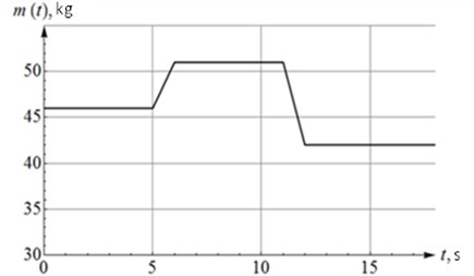
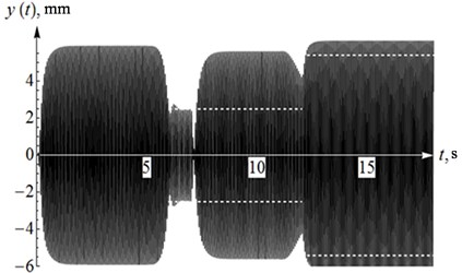
In the numerical validation of the algorithm, the change in mass of the system was given as shown in Fig. 3, displacement of the platform shown in Fig. 4. It can be seen that three time intervals of steady oscillations of the platform that correspond to the time intervals in Fig. 3 with a constant mass of the system. Note that transient processes occur without any jumps in the vibration amplitude. The dashed lines in Fig. 4 show the corresponding values in case of the system without regulation.
5. Conclusion
The developed algorithm for automatic adjustment is based on constructing a dynamic portrait of the system and allows to bring the machine to the resonant regime. The developed approach is universal and can be applied at varying other system parameters.
Fig. 4Displacement of the platform
References
-
Astashev V., Babitsky V., Vulfson I. Dynamics of machines and machine control. Mechanical Engineering, Moscow, 1988, (in Russian).
-
Blekhman I. I. Vibrational Mechanics. Nauka, Moscow, 1994, (in Russian).
-
Kononenko V. Oscillatory Systems with Limited Excitation. Nauka, Moscow, 1964, (in Russian).
-
Vibration in the technique. Handbook. In 6 Vols. V. 4. Vibration processes and machines. Mechanical Engineering, Moscow, 1981, (in Russian).
-
Niselovskaya E., Panovko G., Shokhin A. Oscillations of the mechanical system generated by an unbalanced rotor asynchronous electric motor. Journal of Machinery Manufacture and Reliability, Vol. 6, 2013, p. 17-23, (in Russian).
-
Sokolovsky G. AC Drives with Frequency Regulation. Academia, Moscow, 2006, (in Russian).
About this article

The reported study was partially supported by RFBR, research project No. 13-08-00461-a.
