Abstract
Problems related to design of high-performance vibrating machines are described in this paper. For this purpose, numerical simulation of flat solid body oscillations excited by two unbalanced exciters was carried out. The developed model takes into account AC motor characteristics. A control system for automatic resonant tuning under varying system parameters is developed.
1. Introduction
Modern vibrating machines typically operate on above-resonant or below-resonant modes. But it was shown that energy is used in the most efficient way on resonant mode [1]. Practical application of resonant vibrating machines is associated with certain engineering problems. One of this problems is that resonant mode is unstable in nonlinear systems such as a typical vibrating machine. Moreover, some parameters of a real vibrating machine (such as operation load) could change during operation. Hence it is necessary to use a control system to tune such a machine to resonant mode continuously.
The issue of stabilizing resonant vibrating machines with unbalanced exciters driven by AC motors is studied insufficiently so far.
This paper is devoted to the development of a control system which keeps a machine with two unbalanced exciters and 3 DOF of working body in resonant mode. Design scheme that corresponds to the experimental setup described in [2] is considered.
2. Design scheme of the machine
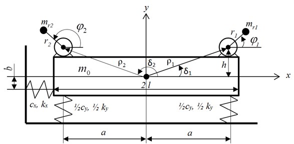
Design scheme of a typical vibrating machine with working body that has 3 DOF in plane is shown in Fig. 1. Working body (referred as platform further) is modeled as a rigid body on viscoelastic support that has linear characteristics. Two unbalanced rotors (exciters) are arranged symmetrically about the axis passing through the center of mass of the machine. Rotors’ axes are parallel to each other and perpendicular to the plane (Fig. 1).
Fig. 1Design scheme

Cartesian coordinate system is used to describe motion of the machine. Origin of the coordinate system is aligned with static equilibrium position of the platform’s center of mass. Axis is directed upwards.
Unbalanced exciters are driven by identical AC motors. The motors are connected to three-phase AC mains via a single frequency converter so that its rotors rotate in opposite directions.
Rotors are driven by torques , . Thus, the system oscillates in the plane .
3. Mathematical model
Motion of the system is described by five generalized coordinates: the linear displacements of the platform’s center of mass in the and directions, rotation angle of the platform and rotors’ rotation angles and . All angular coordinates mentioned here are measured from the axis counterclockwise. Differential equations of motion for the system have been derived using Lagrange equations of the second kind [3]:
here: , – unbalanced masses of rotors, , – eccentricities of unbalanced masses, , – moments of inertia for unbalanced rotors; – full mass of the system; – mass of the platform; , , – damping coefficients of supports in a horizontal, vertical and angular directions respectively; , , – stiffness coefficients of the supports in horizontal, vertical, and angular directions respectively; , – distance from the platform’s center of mass to the axes of rotors respectively; , – angles between the axis and the axis, which pass through platform’s center of mass and axis of rotors in plane (counted counterclockwise), and , , where is distance between the axis of rotor and axis Ox; is distance between springs, (see Fig. 1); – moment of inertia of the system; – moment of inertia of the platform; – gravitational acceleration; – constants that define the direction of rotors’ rotation; – resistance moment for the rotors.
Torques , in right parts of Eq. (1) could be described by static characteristic of motors. These characteristics are obtained using simplified Kloss formula:
where , – critical (maximum) torques for each motor, , – slip at critical torque, , – current slip determined by frequency and angular velocity of rotors , , is number of poles pairs.
4. Mathematical model verification
It is necessary to specify numerical values for the parameters in Eqs. (1-2). Numerical values that correspond to the experimental setup described in [2] are used for calculations: platform mass kg; unbalanced mass of rotors kg; eccentricities of unbalanced masses m; geometrical parameters of rotors' axes m, 13.71°, 166.29°; platform length parameter m; inertia moment of the platform kg∙m2; inertia moment of the rotors 2.0175∙10-6 kg∙m2.
Here motors with slightly different parameters are considered to figure out all possible normal modes of the oscillating system. Maximum torques N∙m; resistance moments for the rotors N∙m; maximum slips 41.6 %, here is motors’ overload capacity, 10 % – nominal slip.
Also it is necessary to specify stiffness parameters , , and damping parameters , , . All these parameters could be determined by comparing calculated values of resonant amplitudes and resonant frequencies with experimental data obtained in [2].
As a result of the verification, the following values of unknown parameters were set: 420 kN/m, kN/m, N∙m; N∙s/m, N∙s/m, N∙s2/m.
5. Control system synthesis
The control system is designed to tune a vibrating machine to resonant mode when some system parameters change slowly.
Usually it is difficult to measure some system parameters like operation load. So the control system based on operation principle described in [4] was developed. This principle is based on controlling phase shift between platform oscillation law and driving force acting on the platform. This phase shift equals to in resonant mode. In this paper a 3 DOF system is described in contrast to the paper [4], where a 1 DOF system is described. The system shown in Fig. 1 has three resonant states and three normal modes correspondingly. In this paper only tuning to the vertical resonant oscillation mode is described.
It is necessary to increase supply frequency slowly to reach maximum possible magnitudes in described case. So below-resonant mode must be initial state of the system. If the system is in above-resonant mode it should be tuned to bellow-resonant mode first. The system is considered to be close to resonant mode if the following condition is satisfied:
where is pre-specified accuracy of resonant tuning.
A control algorithm based on the solution of linearized equations of motion assuming unlimited power of electric motors () could be proposed [5].
One can easily derive expression for phase shift in linearized system [6]:
where is natural frequency of the linearized system. Thus, approximation for could be derived from Eq. (4):
It is assumed here that and could be obtained from experimental data. So it is not necessary to know mass to estimate eigenfrequency of the system.
To tune the system to resonant mode supply frequency should be set via frequency converter. And then supply frequency should be set cyclically on the ()-th step of regulation until Eq. (3) is satisfied.
If the system is tuned to above-resonant mode during regulation on, suppose, ()-th step of regulation () than it should be returned to the previous step of regulation with supply frequency and then supply frequency should be set to the new value , . The cycle repeats again until Eq. (3) is satisfied.
It should be noted that only calculated in steady state values of the phase shift are correct. Steady state identification is a separate problem. We propose to track changes of current phase shift to identify steady state.
Phase shift could be calculated using some experimental data: platform displacement and rotors’ angular positions. For any moment , when the platform is in the static equilibrium position, phase shift is determined by the formula:
where is angle of total driving force direction, n is number of full revolutions in .
6. Simulation results
Numerical values for simulation correspond to the values described in Mathematical model verification part of the paper. Initial condition for numerical integration is state of static equilibrium.
The simulations were carried out for above-resonant mode as initial state ( Hz). This case is more general because the control system must tune the machine to the below-resonant mode first.
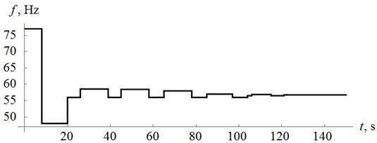
Simulation results are presented in the form of time diagrams of power supply frequency (Fig. 2), generalized coordinate of the platform (Fig. 3), phase shift between the estimated value of and the driving force (Fig. 4).
Fig. 2Supply frequency law of change

Fig. 3Platform oscillation law

One can find out that tuning process takes quite large number of iterations in this case, with jumps to above-resonant modes.
Tuning time expected to decrease if to increase the value of the damping parameter .
Fig. 4 shows that the developed control system tunes the machine to near-resonant mode successfully (here 90° corresponds to resonant mode). Thus, simulation shows that the developed algorithm for control system allows to tune the machine to near-resonant mode.
Fig. 4Phase shift Δε

7. Conclusions
The mathematical model for the controlled vibrating machine was developed. The model could be used to research some dynamic phenomenon in vibrating machines and to simulate controlled machine operating.
The developed algorithm for control system is based on linearized equations. Simulation shows that the developed algorithm tunes the machine to near-resonant mode and could keep the machine in this mode even if system parameters change over time.
References
-
Astashev V., Babitsky V., Kolovsky M. Dynamics and Control of Machines. Springer, 2000.
-
Panovko G., Shohin A., Eremeykin S. Experimental analysis of the oscillations of a mechanical system with self-synchronized inertial vibration exciters. Journal of Machinery Manufacture and Reliability, Vol. 44, Issue 6, 2015, p. 492-496.
-
Blekhman I. Synchronization of Dynamic Systems. Nauka, Moscow, 1971, (in Russian).
-
Panovko G., Shohin A., Eremeykin S. The control of the resonant mode of a vibrating machine that is driven by an asynchronous electro motor. Journal of Machinery Manufacture and Reliability, Vol. 44, Issue 2, 2015, p. 109-113.
-
Panovko G., Shohin A., Eremeykin S., Gorbunov A. Comparative analysis of two control algorithms of resonant oscillations of the vibration machine driven by an asynchronous AC motor. Journal of Vibroengineering, Vol. 17, Issue 4, 2015, p. 1903-1911.
-
Biderman V. The Theory of Mechanical Oscillations. High School, Moscow, 1980, (in Russian).
About this article
The study was performed account for the grant of Russian Science Foundation (Project No. 15-19-30026).
