Abstract
The dynamics of an unbalanced rotor with a vibrating suspension axis and driven by an asynchronous electric motor of limited power is considered. Stationary (near stationary) modes of rotation of the rotor with a frequency equal to the vibration frequency of the axis are investigated. An explanation of the phenomenon of vibrational capture of rotation of an unbalanced rotor is given. The proposed mechanical interpretation of the effect allows deeper understanding of the classical results and conclusions. The obtained condition for the existence of a stationary mode allows us to estimate the frequency capture interval of the rotor. The case when the mode of vibration capture of rotation is not set is considered. For such a case, an expression for the vibrational moment is obtained, as well as an equation for slow motions. Attention is drawn to the possibility of occurrence in the considered modes of motion of slow (relative to the rotation frequency) rotor oscillations with sufficiently large amplitudes. It is demonstrated that the vibrational capture mode has the property of self-regulation; allows to stabilize the rotation frequency of an unbalanced rotor during load oscillations. Attention is drawn to the fact that in this mode of motion, there is certainly a transfer of energy either from the source of vibration to the rotor, or vice versa. The Sommerfeld effect in an oscillatory system with an inertial vibration exciter is represented by vibration capture of rotation of the vibration exciter by resonant oscillations of the carrier body. The theoretical results are confirmed by numerical modelling.
1. Introduction
The effects and patterns of behavior of an unbalanced rotor, the axis of which performs specified periodic oscillations, are of great theoretical interest and wide practical use. It is important that a barely noticeable vibration of the axis of an unbalanced rotor can significantly affect its dynamics.
A large number of works are devoted to the analysis of these effects. An overview and generalization of the main research results are given, for example, in monographs [1, 2]. The vast majority of the results obtained relate to the main mode in which the rotor rotates with an average angular velocity equal to the vibration frequency. The study of stationary modes of rotation of the rotor with a frequency multiple of the vibration frequency of its axis is given in [3, 4]. Practically important issues related to the determination of the field of attraction of certain stationary modes of rotation of the rotor under the action of axis vibration were considered in [5, 6].
Among the recent works devoted to the practical use of the effect, we can note the articles [7-11]. In [7] a mathematical model was found, and numerical results obtained for the pendulum behavior when coupled to a DC generator. A simple pendulum is vertically excited on its support and consequently exhibiting oscillations and rotations. Nonideal interactions of a DC motor with a pendulum by a crank-shaft-slider mechanism is analyzed and compared with an ideal excitation of the pendulum. The paper [10] analyzes the possible motion modes of an unbalanced rotor with an auto-balancing device. It is shown that for given parameters of the system, there are several qualitatively different stable motion modes. A qualitative analysis of the stability ranges of all possible motion modes of the system was performed. This article [11] presents the synthesis of design parameters of a two frequency inertial vibrator according to the specified power characteristics.
The proposed work is devoted to the further development of studies of the effect of vibration capture of the rotation of an unbalanced rotor, given in [1, 2, 12]. In [1, 2], the main attention is paid to: determination of vibrational moments; finding possible stationary modes of rotation of a rotor and studying their stability. At the same time, a detailed analysis of the basic equations of vibrational mechanics was not carried out. The practical importance of such studies was pointed out in the report [12]. However, the results presented in [12] are incomplete.
In this article, a more detailed analysis of the equations of slow and fast movements of an unbalanced rotor is made. In addition, an expression for the vibrational moment is obtained for the case when the vibrational capture mode is not established. The work uses the approach of vibrational mechanics and the method of direct separation of motions of prof. Blekhman [1, 2]. The advantages of this approach and method are relative simplicity and physical interpretability. This made it possible to formulate more applied findings and conclusions than in known works.
2. Statement of the problem and equation of motion
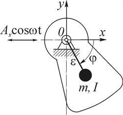
Consider an unbalanced rotor (unbalanced vibration exciter) with a vibrating suspension axis. Let the rotor axis make a given harmonic oscillations excited by an ideal energy source according to the law , where and are the amplitude and frequency of the oscillations of the rotor axis, respectively (Fig. 1). For the sake of concreteness, let's assume that the rotor axis is horizontal, and its oscillations occur in a horizontal direction. Note that such a scheme of the dynamic system was chosen for a convenient comparison of the obtained results with the results of classical studies [1, 2]; consideration of more general cases of axis vibration does not lead to fundamentally new results, but requires more cumbersome calculations. At the same time, the simplest example under consideration allows us to find out the features of the dynamics of an unbalanced rotor with a vibrating axis.
The equation of motion of an unbalanced rotor is represented as [1]:
where , , are accordingly, the moment of inertia, mass and eccentricity of the unbalanced rotor; is the angle of rotation of the rotor, counted clockwise; is torque transmitted from the electric motor; is the moment of the forces of resistance to rotation of the rotor; is acceleration of free fall.
Fig. 1Unbalanced rotor with vibrating axis
We believe that the moment in the general case can take into account not only the resistance in the rotor bearings, but also the payload; the rotor is driven by an asynchronous type electric motor. Taking into account that stationary (near stationary) modes of rotor motion are studied below, the moment of the electric motor will be taken into account using its static characteristics. We investigate the rotation of an unbalanced rotor with a frequency equal to (or close to) the frequency of uniform rotation .
3. Equations of slow and fast movements of an unbalanced rotor and their analysis
Using the method of direct separation of movements, we consider the movements of the rotor of the form , where – slow, and – small fast -periodic function, the average value of which is zero for the period. Following this method, we write down the equations for the functions and in the form [1, 12]:
where is the total damping coefficient, and ; ; .
Let us note: the coefficients , are obtained as a result of the linearization of moments , near the frequency ; angle brackets indicate the averaging of the expression contained in them over a period of fast time ; the expression is the so-called vibration moment [1; 13, 14] – the average value of the additional moment caused by vibration.
To determine the vibration moment with sufficient accuracy for most applications, the equation of rapid motion can be solved approximately. To do this, as in [1], we represent Eq. (3) in the form: , where is a small parameter; . In the zero approximation () we have:
where is maximum value (modulus) of vibration moment.
As can be seen, with equal rotational frequencies of the rotor and the vibration of the axis, the “fast” moment due to the portable force of inertia leads to the appearance of a vibration moment in the equation of slow movements.
Eq. (2) leads to the following relation for determining the phase shift in stationary modes of vibrational capture of rotor rotation ():
The condition for the possibility of the existence of these modes has the form: [1]. When the speeds and are not too different from each other, this condition can be represented in the form , where is the rotor frequency capture interval; – the speed of steady rotation of the rotor in the absence of axis vibration. For cases where the moment of resistance to rotation is mainly due to the resistance in the bearings, the above inequalities can be written in an approximate form:
where , , rated torque, rated and synchronous motor speed, respectively.
Note that when obtaining condition Eq. (6), it is taken into account the significant difference between the dependences of moments and on the rotor speed, as well as the expression [13].
Condition Eq. (6) is convenient to use for a rough assessment of the possibility of the existence of a vibrational capture mode of rotation; it allows you to estimate the frequency capture interval of the rotor. It is obvious that: inequality (6) physically means the requirement of limited engine power; when the rotor rotates with a frequency close to the frequency of axis oscillations , condition Eq. (6) is necessarily fulfilled. Consequently, even a relatively small vibration with a frequency equal to the frequency of the rotor (close enough to it) can lead to the emergence of a mode.
From relations obtained it follows that vibration: can lead both to a decrease in the average speed of the steady rotation of the rotor, and to its increase; seeks to change the rotor frequency to the vibration frequency and maintain a certain phase shift . Moreover, the vibration can stabilize the stationary rotation frequency of the rotor under the sudden load changes. Changes in load (within condition Eq. (6)) are compensated by changes in the vibration moment Eq. (4).
When inequality Eq. (6) is fulfilled, Eq. (5) has two significantly different solutions: . The condition for the stability of these solutions is reduced to the fulfillment of the inequality [1]. In case when the rotor frequency coincides with the oscillation frequency of the axis , the stationary solutions of Eq. (2) will be: and . The other solutions differ from on , where ; at the same time, the solution is stable.
It follows from expression Eq. (4) that the slightest deviation of the angle from a stable value leads to the appearance of a vibrational moment (restoring moment). At the same time, the vibration moment takes either a negative or a positive value. Consequently, in the stationary mode, the action becomes quite definite: only braking or only rotating. Hence, the nature of the vibration effect is determined, first of all, by the steady phase shift between rotational and oscillatory movements. The magnitude of the phase shift will be greater with a longer capture interval , more engine power and less vibration moment modulus.
It is not difficult to establish that when the frequencies and coincide, the effect of the vibration moment is reduced to the establishment and subsequent maintenance of a stable phase shift . Fig. 2 shows a graphical interpretation of the above. The stationary modes of vibrational capture of the rotor rotation correspond to the abscissae of the intersection points of the graphs of the functions and; ; for the case , the graph is a straight line coinciding with the axis of the abscissae. Naturally, an increase in the ordinate indicates an increase in the vibrational moment; at the same time, above the abscissa axis there is a delayed braking moment, below it there is a torque (respectively, the horizontal arrows on the graph of the moment change are directed to the left and right). This means that when the rotor is removed from a stable position () in the direction of increasing the angle (, i. e. the rotor “overtakes” (outstrips) the vibration), the vibration moment will slow down the rotor. And vice versa, when the rotor is removed from a stable position in the direction of decreasing the angle (the rotor “lags behind” the vibration) – push the rotor. When the rotor moves near an unstable position (), the vibration moment tends to remove the rotor from this position.
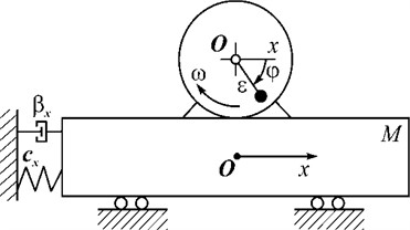
It should be noted that the above interpretation allows better understanding of the effect of vibrational braking of the inertial vibration exciter during the “slow” passage of the oscillatory system resonance (Fig. 3). It is known that during the run-up of the vibration exciter, a phase shift between the disturbing force and the carrier body oscillations arises and increases (in Fig. 2, the run-up corresponds to the change in angle from zero to a value close to ). Consequently, during the run-up, the vibration exciter “overtakes” (outstrips) the axis vibration. Accordingly, a braking vibrational moment arises and increases. In case of limited engine power, this circumstance can lead to a “stuck” of the vibration exciter speed, i.e. to the Sommerfeld effect. After passing the natural frequency of the oscillatory system (phase shift exceeds ), the braking vibration moment rapidly decreases. Naturally, in case of a “fast” passage through the resonance zone, the significant braking effect of the vibration will be short-lived.
Fig. 2Graphical interpretation of stationary rotor motion modes and their stability: 1 – y1=Lω-Rω, case Lω-Rω=0; 2 – y2=Vmaxsinα; 3 – y1=Lω-Rω, case Lω-Rω>0
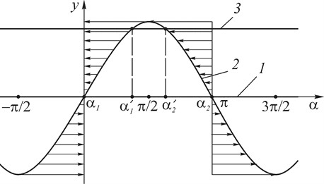
Fig. 3Diagram of vibration machine with inertial vibration exciter
Let us consider the equations of fast movements of an unbalanced rotor Eq. (3).
Applying the approach used in the article [15], the Eq. (3) is transformed to the form (the action of gravity is neglected):
where .
It follows from the foregoing that in stable stationary modes the stiffness coefficient will be constant and positive; when the value of the function will be close to one. It appears that the moment can be quite large. Thus, in the mode of vibrational capture of rotation, the equation of rapid movements takes the form of an equation of an oscillatory type. It is easy to make sure that the natural frequency is several times less than the frequency . Note that the last expression for the frequency coincides with that obtained in [1, 2]. At the same time, in contrast to the one given in [1, 2], Eq. (7) describes an oscillatory process that is superimposed on the main movement of the rotor in the vibratory rotation capture mode.)
Consequently: in the case of equal (close) frequencies of rotation of the rotor and vibration, when the vibration capture mode is established, a pronounced transient process with the main slow frequency will take place; in the steady state, the amplitude of oscillations of the rotor speed will be relatively small; at the same time, their value will significantly depend on the vibrational moment modulus; as the interval increases, the stiffness coefficient (frequency ) decreases rapidly. Note that in the vibration capture mode, only high-frequency oscillations of the rotor.
Let us consider the case when the rotor rotates with a certain frequency close to the frequency of uniform rotation ; moreover, the frequencies and satisfy the condition . Using the method of direct separation of movements, we again come to the equation of slow rotor movements in the form Eq. (2), where ; . Obviously, the phase shift can be considered a slowly changing function of time. Taking into account the basic assumption of the method used that all slow variables can be considered constants (“frozen”) [1], is . Then Eq. (2) can be represented as:
As it can be seen, in the considered approximation, changes in the vibrational moment will occur according to the harmonic law; the average value for the period will be equal to zero. However, since the changes will be slow, the average effect of vibration can be discussed. Consequently, for a sufficiently long time (), the rotor will alternately be affected by a rotating, then a braking vibration moment. Note that the maximum value of such a moment () can be very significant [1].
Obviously, due to slow periodic changes in the vibration moment, there will be fluctuations in the rotor speed with frequency . The amplitudes of these oscillations can be approximately determined by the expression: . From Eq. (3), taking into account the first approximation, it is not difficult to obtain an expression for the amplitude of the fast oscillations of the rotor speed: . As it can be seen, . Therefore, if the vibration capture mode is not established (condition Eq. (6) is not fulfilled), then the rotor speed oscillations will be significantly greater than in the case of such a mode being established. If condition Eq. (6) is true, the oscillations described by Eq. (8) will be short-term since when the frequency of the rotor coincides with the vibration frequency, the vibration capture mode will certainly be established.
4. Results and discussion
An analysis of the basic equations of vibrational mechanics allows us to draw the following conclusions. It is convenient to evaluate the impact of vibration using the vibrational moment. From Eq. (4) it follows that with the parameters of the rotor and the vibration of the axis fixed for a certain mechanism (characterized, respectively, by static torque and vibration acceleration ), the vibration effect is determined only by the magnitude of the phase shift .
Consequently, in the case of establishing a stationary mode of vibrational capture of rotation (), the effect of vibration, on average, becomes unambiguous: only braking when the vibration frequency of the rotor is less than the frequency of its rotation; or only rotational – when . As you can see, vibration can change the moment of resistance to rotation of the rotor, and, consequently, lead to a change in the speed of steady motion; at the same time, both reducing and increasing it.
Thus, at equal (close) rotational frequencies of the rotor and vibration, the action of the latter leads to the appearance of a vibrational moment – directed (defined), on average, the vibration effect on the rotor. It is important that in this case only high-frequency vibrations of the rotor take place; at the same time, their amplitudes will be relatively small.
If the vibration capture mode of rotation is not set, there will be no unambiguous effect of vibration on the movement of the rotor. The moment of portable inertia forces alternately either slows down or pushes the rotor. The average vibration action is zero. At the same time, along with high-frequency oscillations of the rotor, its low-frequency oscillations take place.
In addition, with the proximity of frequencies and , a rotor motion mode may occur, characterized by relatively slow (rocking) oscillations of the dynamic (vibrational) moment. Despite the fact that, on average, the vibration effect is zero, slow changes in the vibration moment can cause large oscillations of the drive.
The possibility of a vibrational capture mode occurrence can be estimated by comparing simultaneously the values of moments and , and frequency intervals and . Obviously, the greater the vibration moment and the smaller the capture band, the milder is the condition for the existence of the mode; even a relatively small vibration with a frequency equal to (fairly close to) the frequency of the rotor can affect its movement.
This means that in an oscillatory system with an inertial vibration exciter (Fig. 3), the effect of vibration capture will certainly manifest itself (the frequencies of the vibration exciter and axis oscillations are the same). The occurrence and increase of the phase shift between the disturbing force and oscillations during start-up is accompanied by the occurrence and increase of the braking vibration moment. As a result, the increase in the frequency of the rotor when approaching the natural frequency slows down. If the phase shift exceeds the value , it entails a rapid decrease in the braking vibrational moment. The consequence of a rapid decrease in load is a rapid increase in the frequency of the exciter. As it can be seen, the Sommerfeld effect in an oscillatory system with an inertial vibration exciter can be explained by the vibration capture of its rotation by resonant oscillations of the carrier body.
The vibratory rotation capture mode has the property of self-regulation: changes in the load on the rotor are compensated by changes in the vibration moment, thereby maintaining the rotor frequency at the level of the vibration frequency. This circumstance makes it possible to use vibration rotation capture to stabilize the rotor rotation speed.
Eq. (4) is the equation of equilibrium of the average moments acting on the rotor. It is also an equation of the energy balance in the system. This means that in the mode of vibrational capture of the rotation of the rotor, there is certainly a transfer of energy. Depending on which of the frequencies or turns out to be higher, energy will be transferred either from the rotor (motor) to the vibration source, or vice versa. Note that there is not a periodic exchange of energy between the rotor and the vibration source, but its transmission in one direction. In the stationary mode of vibration capture, the vibration of the base on which the rotor is mounted acts as a power transmission channel. The “bandwidth” of such a channel can be relatively large [1].
Analysing the oscillatory process, which is superimposed on the uniform rotation of the rotor, it can be concluded that the vibration moment is the restoring moment. It occurs at the slightest displacement of the rotor from the position corresponding to a steady phase shift , and is directed so as to return the rotor to this position. As it can be seen, the role of the restoring force for the rotor, along with the forces of gravity, can be performed by the vibrational force. Consequently, the vibrational moment determines the intrinsic vibrational properties of the dynamic system “an unbalanced rotor with a vibrating axis”. The occurrence of “slow” (in comparison with ) rotor speed oscillations in the occurrence of stationary modes is associated with the excitation of its own oscillations. It is noteworthy that the amplitudes of such oscillations can be large. The frequency can be considered critical for an unbalanced rotor with a vibrating axis. It is obvious that an increase in the intensity of vibration () and the unbalance of the rotor () leads to an increase in the frequency of “slow” oscillations of the rotor. It should be noted that such oscillations have found practical application to facilitate the start-up of vibration machines with an inertial drive [2, 16].
It follows from the foregoing that the vibration moment is the synchronizing moment for the rotor. It seeks to coordinate the rotation of the rotor with the axis oscillations; to change the frequency of the rotor to the frequency of vibration; at the same time, to maintain a certain phase shift. Thus, vibrational capture can be considered as a limiting special case of frequency and phase self-synchronization. As it can be seen, the tendency to synchronization for an unbalanced rotor can manifest itself with minimal axis vibration. This circumstance explains the possibility of vibration capture for multiple modes of rotor rotation and vibration. As is known, in such modes the vibrational moments are significantly less than in the main mode.
5. Comparison with the results of computer simulation of the effect of vibration capture rotation of an unbalanced rotor
The numerical solution of Eq. (1) was carried out in the mathematical package Maple 14 using a dynamic model of an asynchronous electric motor ([17], as well as described in the author’s article in the book [18]). The basic parameters in equation (1) were set as follows: 20 kg; 0,02 m; 0,05 kg⋅m2; 0,002 m; an electric motor 1,5 kW with a synchronous speed 1500 rt m was used. After starting the electric motor and establishing a stationary rotation mode, the rotor axis begins ( 1,1 s) to make vertical harmonic oscillations according to the law .
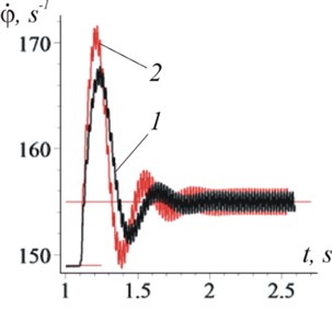
The establishment of the vibration capture mode is demonstrated for cases when the vibration frequency is greater (Figs. 4 and 5) or less (Figs. 6 and 7) than the rotor rotation speed before vibration occurs .
Fig. 4Changes over time of rotor frequency (case ω<ω0)
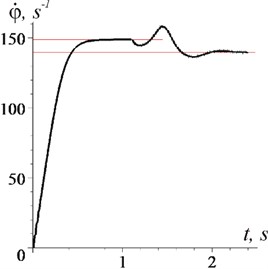
a) From the moment of start
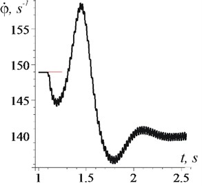
b) From the moment of time 1 s
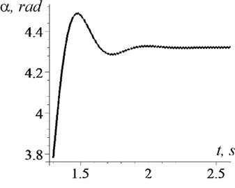
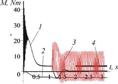
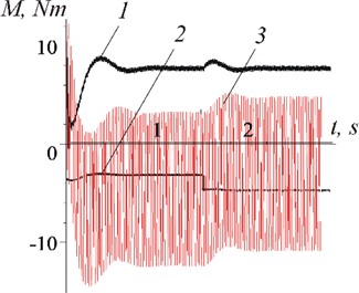
Fig. 5Changes over time (case ω<ω0)
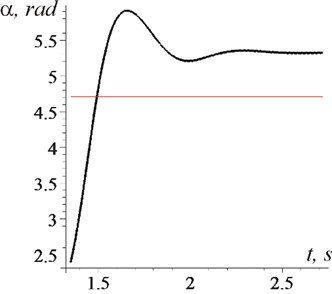
a) Phase shift
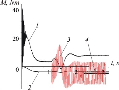
b) Moments: 1 – ; 2 – ; 3 – ; 4 –
It is clearly seen from the graphs that after the establishment of a stationary mode: the average rotor rotation frequency stabilizes at a level equal to the vibration frequency (Fig. 4: 140 s-1 and Fig. 6(a): 155 s-1, when 148,9 s-1); the phase shift becomes constant Fig. 5(а): 5,34 rad and Fig. 7(а): 4,32 rad); the effect of vibration, on average, becomes unambiguous - braking (Fig. 5(b): –4,5 Nm-1) or rotational (Fig. 7(b): 3,5 Nm-1). When establishing a stationary mode, a short transient process with a large amplitude of oscillations and frequency can be observed (in Fig. 4: 10,5 s-1; according to formulas: 11,3 s-1; in Fig. 6(b), curve 1: 15,3 s-1, curve 2: 19 s-1; according to formulas 17 s-1 and 19,6 s-1 respectively). It is important that in the steady–state mode of motion, only high-frequency vibrations of the rotor (with frequency 314 s-1) take place, and low-frequency ones are absent.
Fig. 6Changes over time of rotor frequency (case ω>ω0)
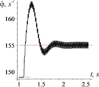
a) 0,002 m
b) 1: 0,003 m; 2: 0,004 m
Figs. 8 and 9 demonstrate the possibility of stabilizing the rotor speed with load changes. Despite the fact that the moment of resistance increased or decreased by half ( 1,5 s, Fig. 9(a) and (b), curve 2), the rotor rotation speed (after a short transient process) remained equal to the vibration frequency (140 s-1), Fig. 8). The torque of the electric motor also remained the same (Figs. 9(a) and (b), curve 1). As follows from the graphs (Fig. 9), the load change is compensated by the corresponding changes in the vibration moment.
In the case when the vibration capture mode of rotation has not been established (the vibration amplitude has been reduced 0,0002 m), the relatively slow (with frequency 9,1 s-1) oscillations of the rotor speed (Fig. 10(a), curve 1), electric motor moments and inertia forces (Fig. 10(b), curves 1, and 3) take place; phase shift is variable. It should be noted that, despite a significant decrease in the vibration amplitude, the amplitudes of the rotor speed oscillations increased noticeably.
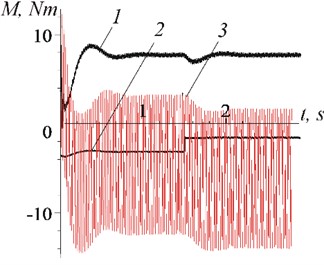
Fig. 7Changes over time (case ω>ω0)
a) Phase shift
b) Moments: 1 – ; 2 – ; 3 – ; 4 –
Fig. 10(а) demonstrates the possibility of a vibration capture mode with minimal vibration amplitudes ( 0,0002 m) in the case of sufficiently close frequencies and ( 149,5 s-1, 148,9 s-1). As it can be seen, after 2,5 s the frequency of rotation of the rotor becomes equal to the vibration frequency (Fig. 10(a), curve 2), at the same time the phase shift becomes constant and close to a stable value. It seems important that the consequence of the establishment of the vibration capture mode is a significant reduction in rotor vibrations.
Fig. 8Rotor frequency changes over time for the following cases: 1 – increase in the moment of resistance forces R; 2 – torque reduction R
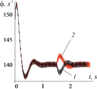
Fig. 9Changes over time of the moments: 1 – L; 2 – R; 3 – Mi for the cases
a) Increasing of
b) Decreasing of
Fig. 10Changes over time
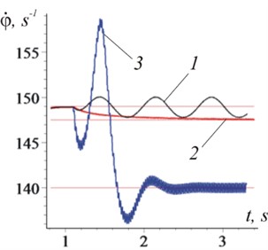
a) Rotor frequency: 1 – vibration capture mode is not established, 0,0002 m, 140 s-1; 2 – 0,002 m, 147,5 s-1; 3 – 0,002 m, 140 s-1 (basic mode, Fig. 3(b))
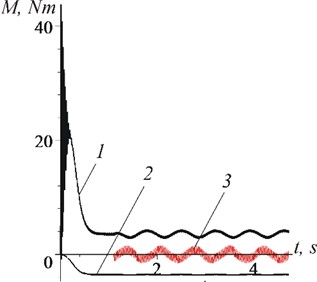
b) moments acting on the rotor (case 0,0002 m): 1 – ; 2 – ; 3 –
6. Conclusions
Vibration of the axis of an unbalanced rotor with a frequency close to the rotation frequency can lead to the appearance of special modes of motion, among which is the vibrational capture of the rotor rotation. In addition to the rotation of the rotor with the vibration frequency, the characteristic features of this mode are: establishment of a certain phase shift between the rotational motion of the rotor and the axis oscillations; on average, a certain (braking or rotating) vibration effect on the rotor; transfer (not exchange) of energy from an unbalanced rotor to a vibration source, or vice versa.
When the vibrational capture mode of rotation occurs, slow (pendulum) oscillations of the rotor speed with its own frequency can be excited. The initial amplitudes of such oscillations can be large.
Vibration of the rotor axis with a frequency close to (equal to) the frequency of its rotation can lead to stabilization of the rotor frequency, with load changes; to a decrease in unbalanced rotor speed fluctuations.
In the case of non-establishment of the vibration capture mode, a motion mode may occur characterized by slow (pulsating) fluctuations in the rotor speed (dynamic moment) with large amplitudes. Such a mode of motion may pose a danger to the drive of mechanisms containing an unbalanced rotor.
References
-
I. Blekhman, Vibrational Mechanics: Nonlinear Dynamic Effects, General Approach, Applications. World Scientific, 2000.
-
I. I. Blekhman, Vibrational Mechanics and Vibrational Rheology (Theory and Applications). (in Russian), Moscow: Fizmatlit, 2018.
-
K. Ragulskis, Mechanisms on a Vibrating Base. Kaunas: Publishing House of the Institute of Energy and Electrical Engineerin, 1963.
-
O. P. Barzukov, “Double synchronization of mechanical vibrators associated with a linear oscillatory system,” (in Russian), Mechanics of a Rigid Body, Vol. 6, 1973.
-
Z. S. Batalova and G. V. Belyakova, “Stability diagrams of periodic movements of a pendulum with an oscillating axis,” (in Russian), Applied Mathematics and Mechanics, Vol. 52, No. 1, 1988.
-
N. V. Kiseleva, “Investigation of periodic movements of a parametrically excited rotor,” (in Russian), Applied Nonlinear Dynamics, Vol. 9, No. 6, 2001.
-
R. H. Avanço, A. M. Tusset, M. Suetake, H. A. Navarro, J. M. Balthazar, and A. Nabarrete, “Energy harvesting through pendulum motion and DC generators,” Latin American Journal of Solids and Structures, Vol. 16, No. 1, p. e150, 2019, https://doi.org/10.1590/1679-78255013
-
A. Tusset, F. Janzen, V. Piccirillo, R. Rocha, J. Balthazar, and G. Litak, “On nonlinear dynamics of a parametrically excited pendulum using both active control and passive rotational (MR) damper,” Journal of Vibration and Control, Vol. 24, No. 9, pp. 1587–1599, May 2018, https://doi.org/10.1177/1077546317714882
-
A. M. Tusset et al., “On energy harvesting from ambient vibrations through an oscillating pendulum system fixed to a suspended platform,” Mathematics in Engineering, Science and Aerospace (MESA), Vol. 11, No. 3, pp. 569–575, 2020, https://doi.org/10.1016/j.jsv.2005.10.003
-
A. Gorbenko, G. Strautmanis, G. Filimonikhin, and M. Mezitis, “Motion modes of the nonlinear mechanical system of the rotor autobalancer,” Vibroengineering Procedia, Vol. 25, No. 1, pp. 1–6, Jun. 2019, https://doi.org/10.21595/vp.2019.20699
-
V. Gursky, P. Krot, V. Korendiy, and R. Zimroz, “Dynamic analysis of an enhanced multi-frequency inertial exciter for industrial vibrating machines,” Machines, Vol. 10, No. 2, p. 130, Feb. 2022, https://doi.org/10.3390/machines10020130
-
N. Yaroshevich, V. Gursky, V. Puts, O. Yaroshevych, and V. Martyniuk, “On the dynamics of vibrational capture of rotation of an unbalanced rotor,” Vibroengineering Procedia, Vol. 42, pp. 1–6, May 2022, https://doi.org/10.21595/vp.2022.22413
-
М. Z. Kolovskii, Dynamics of Machines. (in Russian), Leningrand: Mechanical Engineering, 1989.
-
M. P. Yaroshevich, I. P. Zabrodets, and T. S. Yaroshevich, “Dynamics of vibrating machines starting with unbalanced drive in case of bearing body flat vibrations,” Naukovyi Visnyk Natsionalnoho Hirnychoho Universytetu, Vol. 3, pp. 39–45, 2015.
-
N. Yaroshevich, O. Yaroshevych, and V. Lyshuk, “Drive dynamics of vibratory machines with inertia excitation,” Mechanisms and Machine Science, Vol. 95, pp. 37–47, 2021, https://doi.org/10.1007/978-3-030-60694-7_2
-
D. A. Tomchin and A. I. Fradkov, “Control of rotor passing through the resonance zone on the basis of the method of velocity gradienT,” (in Russian), Problems of Machine Building and Reliability of Machines, Vol. 5, pp. 66–71, 2005.
-
V. Tchaban and V. Lyshuk, Mathematical Model Vnit Power Asynchronous Machines. (in Ukraine), Lutsk, 2013.
-
V. Beletskiy, D. Indeytsev, and A. Fradkov, Nonlinear Problems of Theory of Oscillation and Theory of Control Vibrational Mechanics. (in Russian), Nauka: IMEP of RAS SPb, 2009.
Cited by
About this article

The authors have not disclosed any funding.
The datasets generated during and/or analyzed during the current study are available from the corresponding author on reasonable request.
Nikolai Yaroshevich – project administration conceptualization, formal analysis, investigation, software, methodology. Vitalij Grabovets – visualization. Tetjana Yaroshevich – review and editing. Irina Pavlova – validation, funding acquisition. Irina Bandura – validation, funding acquisition.
The authors declare that they have no conflict of interest.
