Abstract
The aim of conducted and presented in the paper experiment was to check if test rules and equipment to investigate fatigue behavior of a newly design composite panels were set properly. Information about fatigue phenomena of composite materials were shortly presented in the paper.
1. Introduction
The one of the most popular means of transport in UE is a railway. It is a specially suitable for raw materials, e.g. coil, ores, loose rocks and building materials. According to Polish Ministry of Infrastructure [1] the share of railway in a system of transport has been permanently increasing. To cause this sort of transport more and more attractive for the customer many various ventures have to be undertaken. The one of them is being carried on within a grant PBS2/A6/17/2013. The aim of the grant is to designed the way of modernization a carriage to extend the work capacity without repair. The one of analysing method to achieve the goal is to cover the internal surfaces of carriage by material resistant to harsh mechanical loads and weatherproof condition. The examples of weared out carriages are presented in the Fig. 1.
Fig. 1Examples of weared out internal surfaces of carriage
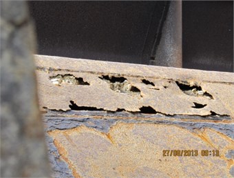
a)
b)
Identified main way of degradation the internal surfaces of carriage is corrosion combined with variable loading. That suggests a necessity of analyzing not only a weatherproof, but also a fatigue phenomena. The initially chosen material to cover walls and bottom of carriage was composite panels.
2. Fatigue of composite materials
The real problem with use a composite panels is to determine their resistance to static and dynamic loading that causes a states of cyclic stress [2-4]. Because of the anisotropic characteristics of strength composite materials are extremely difficult in fatigue analyzing. This phenomena causes a damage throughout the volume of specimen, leading to degradation of the material. This way of destruction is completely different from metals, which behavior is typical for isotropic and brittle material and failure mechanism is observable by present single cracks. For composite material there are a four main independent mechanisms of failure caused by fatigue: matrix cracking, delamination, fiber breakage and interfacial debonding. The comparison of metal and composite fatigue damage was presented in the Fig. 2. The different ways of failure together with anisotropies, complex state of stress and non-linear behavior make the composite materials difficult to understand its nature of fatigue.
Fig. 2A fatigue phenomena within metal and composite materials [5]
![A fatigue phenomena within metal and composite materials [5]](https://static-01.extrica.com/articles/15502/15502-img3.jpg)
There are works with a details analysis concerning method suitable for analyzing the fatigue of composite materials. Generally fatigue failure can be establish either as a loss of strength or as a loss of stiffness [6]. There are a two main ways to determine fatigue life of composite; constant stress cycling to loss the strength and constant amplitude cycling to loss the stiffness.
The loss of strength caused by a cycling loading is confirmed within a static strength test carried out after established number of cycles that deteriorates the sample.
The more popular test to establish fatigue life of composite is related to decreasing its stiffness. The value of load required to deflect the composite sample is great at the beginning of fatigue test and decreases to achieve a little value at the end of test. The value of load is corresponding to a stress level. The less load is required to deflect the composite material, the deterioration of material is getting more significant. A curve of stiffness reduction for composite materials and metal is presented in the Fig. 3.
Fig. 3Stiffness reduction for composite materials and metal [5]
![Stiffness reduction for composite materials and metal [5]](https://static-01.extrica.com/articles/15502/15502-img4.jpg)
The one of differences between composite material and metal is the range of cycling from the spring life to fracture.
3. Composite panel design
Many analysis of various materials were conducted to select the proper one for designing composite panels for internal layer of carriage. The analysis were done after conducting a static tests and simulation in FEM program [7]. The initially selected composite panels were double-layer with aramid fibers reinforced with synthetic resin. According to conducted experiments the highest stiffness had the panel which a mutual angle of rotated layers is 45° (mutual angle of fibers within one layer is 90°). A sample of composite within a stiffness simulation was presented in the Fig. 4.
Fig. 4A sample of composite material within a stiffness tests [5]
![A sample of composite material within a stiffness tests [5]](https://static-01.extrica.com/articles/15502/15502-img5.jpg)
4. The concept of fatigue test of selected composite panel
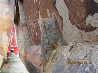
Taking into consideration information shortly presented above the suitable fatigue test for designed composite panel was chosen this with a stiffness analysis with parallel recording of displacement and stress. To conduct necessary tests a special fatigue test machine was made what was presented in the Fig. 5.
Fig. 5A view on a fatigue test machine
The main parts of it are: a frame to clamp the panel and a shaft with a roll to force deflection of a panel. The range of deflection is from 0 up to 80 mm.
5. Preliminary results
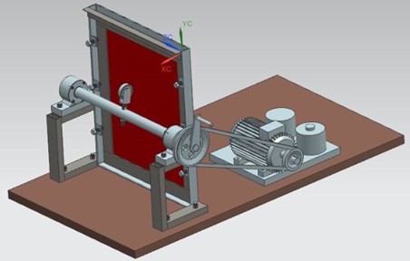
After conducting initial tests a course of displacement and stress were recorded and presented in the Fig. 6. The established number of cycles was 5000 and the value of displacement was 6.5 mm.
The final value of displacement will be established according to results from virtual tests and analysis taking into account a limitation that appears in place of fixing panel to wall of carriage. The low frequency (0.5 Hz) should not cause any additional dynamic effects that are not present in real maintenance conditions.
Fig. 6A displacement and stress recorded within initial fatigue test of composite panel
6. Conclusions
The fatigue test of composite materials that takes into consideration a change of stiffness as a measure of fatigue could be proper to assess the parameters of newly design composite panels for carriage. The initial results confirm that the test and the equipment were combined properly. The measured stress should give an additional useful information about fatigue phenomena of composite panels.
References
-
Master Plan for Railway Transport in Poland Till the Year 2030. Polish Ministry of Infrastructure, Warsaw, 2008.
-
Kim R. Y. Fatigue Behavior, Composite Design. Section 19, S.W. Tsai. Ed. Think Composites, Dayton, Ohio, 1986.
-
Hearle J. W. S. High-Performance Fibres. Woodhead Publishing Limited in association with The Textile Institute, Cambridge, England, 2001.
-
Reid S. R., Zhou G. Impact Behaviour of Fibre-Reinforced Composite Materials and Structures. Woodhead Publishing Limited and CRC Press LLC, Cambridge, England, 2000.
-
Salkind M. J. Fatigue of composites, composites materials: testing and design. American Society for Testing and Materials, 1972, p. 143-169.
-
Marine Composites. Second Edition, Eric Greene Associates, Annapolis, Maryland, 1999.
-
Buchacz A., Jamroziak K., Kosobudzki M., Majzner M. Identyfication of chosen material properties of aramid filaments and numerical simulations of properties of aramid plates. Transportation Industrial and Construction Work, Vol. 24, Issue 2, 2014, p. 121-126, (in Polish).
About this article

The work was carried out as a part of research and development PBS2/A6/17/2013 supported by the National Centre of Research and Development in years 2013-2016.
