Abstract
Shape Memory Alloys (SMAs) are more and more frequently used in civil structures subjected to extreme dynamic loadings. Due to their unique properties, the SMAs are used for seismic retrofit of bridges, tall buildings and masts. The paper presents selected results of numerical calculations of a cable-stayed steel bridge model retrofitted with SMA restrainers. The original set of constitutive relationships describing pseudoelastic properties of SMA was used for this purpose. The formulation of SMA model is based on analysis of a special rheological scheme representing its constitutive properties. The SMA model was implemented within FEM software Abaqus using an user defined subroutine. It was proved that the application of SMA restrainers can reduce significantly vibrations and internal forces caused by seismic excitations.
1. Introduction
Shape memory alloys (SMAs) are characterized by a strong non-linear behavior, associated with two special effects: shape memory and pseudoelasticity. The shape memory effect demonstrates the possibility of the shape recovering upon heating. The strain-induced pseudoelasticity phenomenon, makes the SMA materials capable to recover inelastic strains up to approx. 8 %. A comprehensive description of SMA behavior associated with the stress- or temperature-induced transformations of their crystalline structure is presented in [1, 2].
Applications of SMAs in civil engineering, which are mainly associated with the use of pseudoelasticity phenomenon, are described in detail in a number of studies (see [3-5]). Frequently, they relate to structures exposed to extreme dynamic loads caused by earthquake, impact or explosion. In such cases, an important role is played by a very good damping properties of SMA and its ability to reduce the load transmitted to structural elements. A wide range of applications concerns retrofitting of bridge structures with additional components made of SMA [6].
The objective of our paper is to present selected results of numerical calculations of a cable-stayed steel bridge model retrofitted with SMA restrainers. We will apply the model of SMA material based on analysis of a special rheological scheme representing its constitutive properties. The method of formulation of SMA relationships using rheological schemes was introduced by Zbiciak [7, 8] in case of 1D beam problems and then generalized by Grzesikiewicz et al. [9] for 3D problems. The SMA relationships were implemented herein within FEM software Abaqus using an user defined subroutine. It will be proved that the application of SMA restrainers can reduce maximum vibrations and internal forces caused by seismic excitations.
2. Constitutive model of SMA restrainers
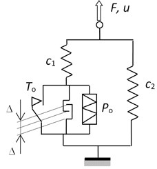
A rheological scheme modelling hysteretic behavior of the force-displacement (-) model of SMA is shown in Fig. 1(a). We applied the idea of modelling of SMA relationships presented in papers [7-9]. Our novel approach was to include additional elements modelling hardening and locking phenomena.
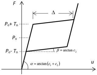
The rheological scheme of SMA (Fig. 1(a)) is composed of five elements. The springs and represent elastic stiffness and hardening properties (compare Fig. 1(b)). The locking element defines the range of non-elastic displacements and is characterized by the symbol in Fig. 1. Another elements modelling plasticity () and pseudoelasticity () were described in details in [8].
Fig. 1Rheological scheme of SMA restrainer a) and its hysteretic loop b)
a)
b)
The rheological model of SMA restrainers presented in Fig. 1(a) can reproduce the 1D hysteretic behaviour visualized in Fig. 1(b). The parameters of the model we will apply for numerical calculations are given in Table 1 based on the data presented in [10].
Table 1Parameters of SMA restrainers (compare Fig. 1)
400 | 20 | 4,0 | 1,7 | 0,06 |
The constitutive model of SMA restrainers was implemented by the authors within Abaqus software. The user defined UAMP subroutine was used for this purpose [15]. The subroutine allows the description of the model using the force-displacement variables. Thus, the characteristics of the restrainers given in [10] can be applied straightforwardly. It should be noted that such a usage of UAMP subroutine is unusual because this subroutine is dedicated for modelling time-varying loads.
3. Cable-stayed bridge model
We assume a hypothetical cable-stayed bridge model (see Figs. 2-5) being discussed in the studies of Abdel-Ghaffar and Nazmy [10], Sarabash and Andrawes [11] and partially Ren and Obata [12]. In terms of some specific solutions we also used the monographs [13] and [14] in order to build computational model. The total length of the bridge is over 1245 m, of which 670.5 m belongs to the middle span. The steel deck is suspended on 48 steel ropes to two reinforced concrete pylons having the height of approx. 171 m. The sectional areas of the suspension ropes vary from 0.01 m2 in case of the shortest ropes to 0.02 m2 for the longest rope.
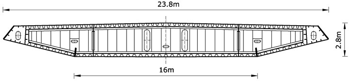
The authors of [10] and [11] do not provide all the details of construction needed to build the numerical model. The greatest difficulty were encountered when trying to reproduce the characteristics of the bridge cross-section. Due to the lack of data, it was decided to adopt a cross-section of the Sutong Bridge (China) (see Fig. 3). Geometrical characteristics of this section were calculated using AutoCAD.
The papers [10, 11] present the idea of the bridge retrofitting with SMA restrainers. A detailed comparative analysis is also carried out in [10, 11] taking into account the influence of the proposed solution on the size of the bridge deck, its displacements movements and internal forces.
According to the observations contained in the paper [11], the rigid coupling of the plate with pylons and bridge abutments, but lead to a reduction of horizontal displacement platform, it is disadvantageous, as they cause a significant increase in lateral forces and bending moments in the pylons. On the other hand, it is also unacceptable to allow totally free movement of plates along the horizontal direction due to too large values of displacements that could occur during exceptional loads. Thus, the idea of installing various types of vibration damping elements arises. Classical viscous dampers allow the effective reduction of displacement, however, the forces in these elements depend on the frequency of excitations. In case of extreme loadings, large forces increasing the stress in the basis of the pylons can occur.
Another solution is to use steel elements as restrainers. Internal forces of such elements only slightly dependent on the force rate. However, as they should not be very stiff, they reach plastic limit very quickly and must be replaced immediately after the occurrence of the earthquake. Because we often have to deal with aftershocks, the solution with steel restrainers is not safe.
Fig. 2Cable-stayed bridge scheme [10, 11]
![Cable-stayed bridge scheme [10, 11]](https://static-01.extrica.com/articles/15491/15491-img3.jpg)
Fig. 3Cross-section scheme of Sutong Bridge (China)
The preferred solution is to replace the steel restrainers by SMA elements. Due to dissipative properties of SMA, this material can reduce vibration of the structure. In addition, SMA restrainers allow to maintain a constant tension in the range of several percent of strain. Thus, the internal forces in the pylons also do not experience significant increases. Since the deformation of the SMA are reversible, it is not necessary to replace these items after each occurrence of adverse events.
Fig. 4 provides details of the deck-abutment and deck-pylon connections. As we can see the presented solution provides tension-compression capabilities of the connection but single restrainer carries only tension.
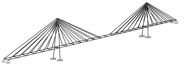
A general three-dimensional view of the FEM model built in Abaqus is shown in Fig. 5. It is a spatial structure built using beam B32 and truss T3D2 elements [16]. The model contains 237 elements and 355 nodes.
Fig. 4Details of deck-abutment and deck-pylon connections [10, 11]
![Details of deck-abutment and deck-pylon connections [10, 11]](https://static-01.extrica.com/articles/15491/15491-img5.jpg)
Fig. 5FEM model of cable-stayed bridge
Two different types of structures were calculated. The first bridge model was retrofitted with linear elastic steel restrainers. This model will be further called comparative. The stiffness of the steel restrainers corresponds to initial stiffness of SMA bars ( in Fig. 1(b)). The second model of the bridge was retrofitted with SMA restrainers characterized in Fig. 1 and Table 1. In case of the comparative model (with steel restrainers), the additional elements (connectors) CONN3D2 and CONN3D2G were used (see [16]). The connectors represent the connections of the bridge deck with abutments and pylons. In case of the bridge with SMA restrainers the connectors were not used because at any time the forces in restrainers were calculated by the UAMP subroutine and applied as external loads to the bridge elements. Dynamic analysis of both structures were carried out using the solver Abaqus/Standard, which uses the implicit algorithm for integration of equations of motion.
4. FEM results
The main part of numerical computation was related to the analysis of the influence of SMA restrainers on the behavior of bridge structure exposed to seismic loads. We used an excitation signal in the form of time-varying accelerations of Koyna earthquake (1967). The signal was applied to the base of one of the pylon along the longitudinal direction of the bridge. Operating time of excitation was equal to 10 s while the total analysis time was 40 s.
Fig. 6 shows a graph of the hysteresis loop in the SMA elements obtained from the numerical simulation. This is the total characteristics of the two restrainers connecting the bridge deck and the pylon to which the excitation was applied.
Vibration charts of the bridge are shown in Figs. 7-8, comparing the results of the comparative model (with steel restrainers) and the SMA bridge. Analyzing the graph in Fig. 7, we can see a significant effect of SMA restrainers on the amplitude of the mid-span vertical displacements. Thanks to the use of SMA, the extreme displacement values have been reduced by approx. 40 %.
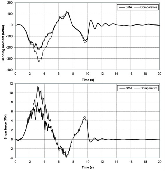
The graphs shown in Fig. 8 show the time histories of bending moments and shear forces in the base of the pylon to which the excitation was applied (maximum components). Extreme values of bending moments and shear forces in the SMA bridge are more than 30 % smaller than in case of the comparative bridge.
Fig. 6Hysteretic loop of SMA restrainers in force-displacement coordinates
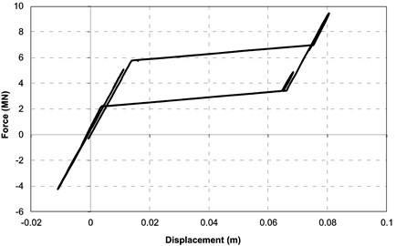
Fig. 7Time history graphs of mid-span vertical displacements
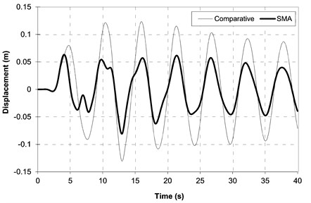
Fig. 8Time history graphs of bending moments and shear forces in pylon base
5. Conclusions
The results presented in previous section indicate significant reduction of vibration and internal forces of the bridge retrofitted with SMA restrainers. The hypothetical cable-stayed bridge model was assumed based on literature [10, 11]. The original element of our paper was the constitutive model of SMA restrainers formulated using the rheological scheme and implemented within the FEM Abaqus software via user defined subroutine UAMP.
It should be emphasized that the numerical model described herein, built with the use of beam and truss elements is relatively simple. Thus, we could concentrate on the implementation of the SMA relationships. In case of real bridge structure design FEM models should be much more complex as their construction needs spatial elements to be used. Such bridge models can contain hundreds of thousands of degrees of freedom. Developing such a model taking into account the SMA restrainers is possible, but probably the effect of vibration reduction would be the same as in case of simple model used in our study.
References
-
Funakubo H. Shape Memory Alloys. Gordon and Breach Science Publishers, London, 1987.
-
Bojarski Z., Morawiec H. Shape Memory Alloys. PWN, Warsaw, 2000, (in Polish).
-
Janke L., Czaderski C., Motavalli M., Ruth J. Application of shape memory alloys in civil engineering structures – overview, limits and new ideas. Materials and Structures, Vol. 38, 2005, p. 578-592.
-
Song G., Ma N., Li H-N. Applications of shape memory alloys in civil structures. Engineering Structores, Vol. 28, 2006, p. 1266-1274.
-
Speicher M., Hodgson D. E., DesRoches R., Leon R. T. Shape memory alloy tension/compression device for seismic retrofit of buildings. Journal of Materials Engineering and Performance, Vol. 18, 2009, p. 746-753.
-
Cardone D., Dolce M., Palermo G. Direct displacement-based design of seismically isolated bridges. Bulletin of Earthquake Engineering, Vol. 7, 2009, p. 391-410.
-
Zbiciak A. Vibration of SMA beam subjected to moving load. Proceedings of the 17th Polish-Russian-Slovak Seminar Theoretical Foundation of Civil Engineering, Žilina, 2008, p. 130-135.
-
Zbiciak A. Dynamic analysis of pseudoelastic SMA beam. International Journal of Mechanical Sciences, Vol. 52, Issue 1, 2010, p. 56-64.
-
Grzesikiewicz W., Wakulicz A., Zbiciak A. Mathematical modelling of pseudoelastic SMA material. International Journal of Non-Linear Mechanics, Vol. 46, Issue 6, 2011, p. 870-876.
-
Abdel-Ghaffar A. M., Nazmy A. S. 3D nonlinear seismic behavior of cable-stayed bridges. Journal of Structural Engineering, Vol. 117, Issue 11, 1991, p. 3456-3476.
-
Sharabash A. M., Andrawes B. O. Application of shape memory alloy dampers in the seismic control of cable-stayed bridges. Engineering Structures, Vol. 31, 2009, p. 607-616.
-
Ren W. X., Obata M. Elastic-plastic behaviour of long span cable-stayed bridges. Journal of Bridge Engineering, Vol. 4, Issue 3, 1999, p. 194-203.
-
Biliszczuk J. Cable-Stayed Bridges: Design and Construction. Arkady, Warsaw, 2006, (in Polish).
-
Jarominiak A. Cable-Stayed Bridges. Publishing House of the Rzeszow University of Technology, Rzeszow, 2002, (in Polish).
-
Abaqus User Subroutines Reference Manual, Ver. 6.12, Dassault Systèmes, 2012.
-
Abaqus Analysis User’s Manual, Ver. 6.12. Dassault Systèmes, 2012.
About this article

